BLE-based Indoor Positioning system for hospitals using miRingLA algorithm
Bạn đang xem bản rút gọn của tài liệu. Xem và tải ngay bản đầy đủ của tài liệu tại đây (7.99 MB, 14 trang )
Science & Technology Development Journal – Engineering and Technology, 2(1):86-99
Research Article
BLE-based Indoor Positioning System for Hospitals using
MiRingLA Algorithm
Le Van Hoang Phuong, Truong Quang Vinh*
ABSTRACT
Over the past decades, locating and navigating to the departments and wards in a large hospital
have never ceased to draw public attention. A large number of human-based efforts and solutions
have been given to deal with the difficulty in location and navigation in a large hospital. However,
the problem is still existing, which urges human to take technology into account seriously. In this
context, an indoor positioning system comes into play, it can not only tackle the trouble but also act
as a prospective platform to build other applications on top of it. Nonetheless, the ever-changing
environment and the heavy dependence on installation stage have precluded many state-of-theart methodologies from practice. In this paper, we present an indoor positioning system based on
Bluetooth Low Energy and applied to hospitals, which is easy-deployed, robust in the noise-rich,
obstacle-rich environment. The system provides 3 principal functions like new medical examination registration, patient's in-app schedule management, and navigation. We implemented a web
application to realize the first function. Besides, an Android application was developed to put ability
up for patients to manage schedules and find ways. Moreover, we proposed a positioning method
that is a modification to inter Ring Localization Algorithm (iRingLA), called MiRingLA. It utilizes 3
rings and Least Squares Estimation to deal with the drawback of the iRingLA. In addition, we applied
a Kalman filter to reduce noises from received signals. The proposed method was experimented
in a practical environment and achieved the mean localization accuracy of 0.91 m. Moreover, we
performed comparisons between our proposed method and some of the others. Our proposed
scenarios were experimented and proved to be feasible and suitable for a real application.
Key words: Indoor Positioning System, Bluetooth Low Energy, iRingLA, iBeacon, Received Signal
Strength Indicator
INTRODUCTION
Ho Chi Minh City University of
Technology - VNU-HCM
Correspondence
Truong Quang Vinh, Ho Chi Minh City
University of Technology - VNU-HCM
Email:
History
• Received: 27-02-2019
• Accepted: 10-4-2019
• Published: 20-8-2019
DOI :
Copyright
© VNU-HCM Press. This is an openaccess article distributed under the
terms of the Creative Commons
Attribution 4.0 International license.
In recent years, the demands on medical services have
been increased. People give more needs for easy medical procedures, patient monitoring, navigation, etc.
Therefore, an indoor positioning system is a promising approach to satisfy their needs and enhance the
quality of hospitals. Indoor positioning systems help
locate objects in a closed area such as a house, building
where the Global Positioning System (GPS) does not
work precisely as designated. In fact, GPS signals vary
rapidly when propagating through these areas, therefore, some other types of signals have been researched
to alternate GPS.
Typically, there are three kinds of signal used for positioning, namely Wi-Fi, Ultra-wide Band (UWB) and
Bluetooth Low Energy (BLE) 1 . Each of them has its
own good features and well-performing contexts.
Wi-Fi has been widely used in many indoor positioning systems. Triangulation, trilateration and fingerprinting are well-known approaches. N. Pritt 2 implemented a system for indoor navigation running on
a smartphone or tablet utilizes Wi-Fi signals. WiFi networks and devices are available in many such
places as schools, shopping malls, and supermarkets. Moreover, Wi-Fi signals have large coverage.
Nonetheless, they consume much power and depend
on infrastructures. In fact, Wi-Fi signals are sensitive
to environments and easy to be interfered by others
in signal-rich environments. In Saab (2010) 3 , the authors offered an indoor positioning system based on
Radio Frequency Identification (RFID). It consists of
a network of readers and numerous passive tags and
yields the average of the absolute position errors of 0.1
m. The advantages of the systems based on this technology are reliability and high accuracy. However,
the common problem is the requirement of numerous
tags and readers which are not cost-efficient. Turan
Can Artunç, Müştak Erhan Yalçin 4 carried out a study
on a UWB-based indoor positioning system, in which
the server received distances from anchors via Wi-Fi
and estimated positions by using trilateration. Their
experiments showed that the system achieved the accuracy of 1.55-8.4 cm. The advantages of UWB-based
Cite this article : Phuong L V H, Vinh T Q. BLE-based Indoor Positioning System for Hospitals using
MiRingLA Algorithm. Sci. Tech. Dev. J. – Engineering and Technology; 2(1):86-99.
46
Science & Technology Development Journal – Engineering and Technology, 2(1):86-99
systems are high accuracy, low energy, and high immunity to the multipath fading. Nevertheless, it is not
cost-efficient and causes interference to other RF signals. Bluetooth Low Energy is a new technology that
has been focused on recently. It is an alternative to traditional technologies such as Wi-Fi, UWB. Nowadays,
BLE is ready for many devices such as smartphones
and beacons which offer a new approach to indoor
positioning. BLE Beacon is a kind of BLE-enabled
devices that continuously broadcasts BLE signal following a specific protocol. iBeacon 5 is a well-known
protocol developed by Apple, Inc. that is widely used
in many BLE beacons. In Chen et al. (2015) 6 , the authors presented a framework of combining the Pedestrian Dead Reckoning (PDR), iBeacons, and a particle filter. Their real experiments achieved the accuracy of 1.2 m. The authors of Li et al. (2016) 7 built a
newborns localization and tracking system in hospitals using iBeacons. Of the deployment patterns and
numbers of iBeacons, 5 beacons placed in the middle
area gave the best performance with the localization
accuracy of 1.29 m.
In this study, we mainly focused on a solution to a
hospital’s existing demands, specifically in locating
and navigating. We performed a study of a positioning method, MiRingLA, which was made up of iRingLA, LSQ, and a Kalman filter. Furthermore, we
researched to provide automatic floor detection and
Dijkstra-based multi-floor navigation. A real experiment was also carried out to evaluate the performance
of our system.
The rest of the paper is organized as follows. The next
section will present the proposed system. Section Positioning Method describes the positioning method,
followed by experimental results in section Experimental Results. Finally, we draw some conclusions
in section Conclusion And Future Work.
PROPOSED SYSTEM
With a view to realizing a practical positioning system applied in hospitals, we consider the system’s mobility, easy maintenance, low energy, and persistence.
We suppose to use BLE beacons which meet above
concerns and MiRingLA positioning method. BLE
beacons are the tiny devices that broadcast BLE signal
periodically and continuously. They are straightforwardly stuck on walls and well-known for their lifespan and low power consumption. MiRingLA makes
the system first-rate for its effortless preparation.
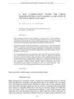
Figure 1 describes the model of the proposed system
which includes 3 principal parts: a web server, smartphones, and BLE beacons. Web server is the center of
the system, it acts as a database server and takes up
47
providing smartphones with maps’ information and
patients’ schedules. Moreover, it provides nurses and
doctors with abilities to register new patients and update their medical records. RSSI denotes Received
Signal Strength Indicator which is the received signal
strength measured by smartphone. The Android application (IPSHApp) runs by smartphones is designed
to show patients’ schedules and directions to the assigned rooms. The positioning method is comprehensively executed by smartphones that requires 3 RSSIs
of 3 separate BLE emitters to find the patients’ positions.
POSITIONING METHOD
Radio Wave Propagation Model
Many localization methods are mainly based on the
Received Signal Strength Indicator (RSSI). Bluetooth
signal is one of the electromagnetic waves that significantly depend on environments. Recent research 8–10
has led to the conclusion that radio waves vary according to types of environment, distances between transmitters and receivers, etc. Some path loss models have
been introduced to predict the propagation loss in environments. In this study, we apply the Log-distance
Path Loss model 8 due to the characteristics of a hospital environment mentioned:
( )
d
+ Xg
PL = PT xdBm − PT xdBm = PL0 + 10nlog
( ) d0
d
RSSI (d) = RSSI (d0 ) − 10nlog
(2)
d0
where d is the distance between the transmitter and
receiver d0 is the reference distance, usually 1m. n is
the path loss exponent that depends on transmission
mediums, usually 2 in offices. FromEquation (2), the
path loss exponent can be expressed as:
n=
RSSI (d0 ) − RSSI (d)
( )
d
10log
d0
(3)
Trilateration and iRingLA
In this section, we review the trilateration 11 and iRingLA 12–14 approaches that are the foundation of our
proposed method.
Trilateration is a classical geometry approach to determine a point’s coordinates using a set of 3 circles
(Figure 2a). When we have coordinates of three beacons and three average distances from them to the receiver respectively, the position is the root of a set of
three circles’ equations:
2
2
2
(x − x1 ) + (y − y1 ) = d1
2
(4)
(x − x2 ) + (y − y2 )2 = d22
(x − x )2 + (y − y )2 = d 2
3
3
3
(1)
Science & Technology Development Journal – Engineering and Technology, 2(1):86-99
Figure 1: The proposed system’s architecture.
Figure 2a indicates that we can only find the exact position if three circles intersect at one unique
point. Due to all the reasons mentioned in section
Radio Wave Propagation Model, we cannot obtain exact RSSIs as well as distances from a beacon to a receiver so three circles do not intersect either at only
one point or at all (Figure 2b). This means we cannot obtain a unique root from Equation (4) by using
a normal solving method.
iRingLA, a new localization method based on trilateration has been introduced and researched that helps
resolve the problems. Instead of using only three circles, iRingLA draws rings around the three anchors
(beacons) (Figure 3). Each of them is made of an inner and outer circle whose radii are expressed as:
{
Ri = Rave − E
(5)
Rout = Rave + E
where E is the error of a specific environment attained
from experiments. The desired point is the centroid of
the common area of 3 intersected rings.
Modified iRingLA (MiRingLA)
In our work, the targeted place is a hospital. Distances
become further and the characteristics of the environment change continuously, signals may be diminished
by walls and obstacles, which causes iRingLA may
neither perform accurately as it designated nor give
any positions at a specific point of time. Figure 3b depicts a case in which the 3 rings do not have any points
in common. In this case, iRingLA cannot locate the
object and the system does not work properly.
We propose a modification to the iRingLA that helps
the object always be positioned. When the 3 rings do
not intersect at all, we apply the Least Squares Estimation (LSQ) 15 into 3 average-radius circles to estimate
the position. The LSQ is to minimize the square error
and with given the estimated distances di and known
positions (xi , yi )of the ith transmitter, the position of
a receiver can be estimated by finding (x, y)satisfied
this equation:
√
(6)
(x, y) = argmin∑3i=1 [di − (x − xi )2 + (y − yi )2 ]2
Let:
2 (xk − x1 )
A = 2 (xk − x2 )
2 (xk − x3 )
2 (yk − y1 )
2 (yk − y2 )
2 (yk − y3 )
(7)
d12 − dk2 − x12 + xk2 − y21 + y2k
B = d22 − dk2 − x22 + xk2 − y22 + y2k
d32 − dk2 − x32 + xk2 − y23 + y2k
(8)
Then the estimated position is the result of this calculation:
[
]
x0
X=
= (AT A)−1 AT B
(9)
y0
Figure 5 shows a brief overview of our proposed MiRingLA. Figure 4 is a geometric illustration of the gridbased computation method proposed to find a receiver’s position:
1: Clusters {C1 ,C2 } ← ring1 ∩ ring2
2: f or each Ci do :
3: Ri ← the rectangle best wraps Ci
4: divideRi intom2 equal cells
(
)
5: Ri ← [ m − 1)2 + 4 points
6: f or each Ri do :
48
Science & Technology Development Journal – Engineering and Technology, 2(1):86-99
Figure 2: Three circles intersect at (a) a unique point (b) many points. The pictures are taken from 10 .
Figure 3: iRingLA: inter Ring Localization Algorithm. Three rings (a) intersect at one cluster (b) do not intersect
at all
Figure 4: Illustration of the grid-based computation of iRingLA.
Figure 5: Summary of MiRingLA.
49
Science & Technology Development Journal – Engineering and Technology, 2(1):86-99
7: Si ← {(x, y) ∈ Ri |(x, y) ∈ ring 1, (x, y) ∈ ring 2} .
8: f or each Si do :
9: Si ← {(x, y) ∈ Si |(x, y) ∈ ring 3}
10: i f Si ̸= ∅ then :
11: position (x, y) ← average (Si }
Kalman Filter
RSSI may be affected by noise in indoor environments, thereby receivers using the RSSI may not
achieve accurate distances. Averaging these values is
a common solution but it also continuously changes
over time. These unwanted average RSSIs will significantly diminish the accuracy of either iRingLA or
MiRingLA. There are various filters able to eliminate
a large part of noise from signal. The authors of 16 applied a Kalman filter effectively to remove noise from
RSSI. In order to deal with the noise problem, we also
apply a Kalman filter to refine received signal, thereby
making the received signal strengths more reliable.
The performance of the Kalman filter was denoted in
Figure 7.
Kalman filter mainly consists of two distinct phases:
prediction and correction and can be written in short
as follows:
• Prediction phase:
{
Xk = AXk−1 + Buk + wk
(10)
Pk = APk−1 AT + Qk
• Correction phase:
K = Pk H(H Pk H T + R)−1
{
Yk = CXkM + Zk
(
)
Xk = Xk + K Yk − H Xk
Pk = (I − KH) Pk
(11)
(12)
(13)
where X - state matrix (X: predicted), P - process covariance matrix (P: predicted), U - control variable
matrix, W - predicted state noise matrix, Q - process
noise covariance matrix, Y - measurement of state, Z measurement noise, R - measurement covariance matrix, H - conversion matrix, I - identity matrix, A state transition matrix, B - control matrix, C - transformation matrix, K - Kalman gain, k denotes the
kth sample.
In our physical model, we assume that in each step of
measurement, the device does not move and the position is also static. A and C are set to identity matrices
as we assume the state is static (i.e. Xk = Xk−1 and
the state is modeled directly (i.e. we assume Y = XkM .
B is set to 0 due to no control. Q is typically set to
a small value (e.g. 0.008). R is set to the variance of
measurements σ 2 (e.g. 4) shown in Figure 6.
EXPERIMENTAL RESULTS
Web server
Being the center of the system, the web server is responsible for providing Android applications hospital maps’ information and patients’ schedules. Moreover, it provides nurses and doctors with abilities
to register new patients and updating their medical
records. We developed the server based on the SailsJs MVC framework. Figure 8a is a nurse-customized
interface contains tables of patients’ information, history and new examination registrations. Figure 8b is
a picture of a doctor’s website which includes patients’
information, history of treatments, prescriptions and
schedules. After registering a new patient (Figure 9a),
the nurse will assign him to a specific room for later
medical procedures by creating a new invoice using
the table shown in Figure 9b. An item will be automatically added to the patient’s schedule. The doctor is in charge of that room will see the assigned patient’s information, and he can provide treatments or
appoint him to another room to take some extra tests
(Figure 10). After all treatments are completed, the
doctor will mark that patient as done to finish his
medical tests.
Android Application (IPSHApp)
The actual position of a device as well as a patient is
estimated using its RSSIs and our proposed positioning method. Navigation is powered by the Dijkstra 17
algorithm. There are 5 main steps to take to attain a
position and a route presented as follows:
1) Create lists of beacons along with their corresponding filtered RSSIs and the average RSSIs.
2) Select the three greatest average RSSIs of three beacons.
3) Use MiRingLA to compute the position (x, y)
4) Create a Dijkstra graph made up of the map’s vertices, edges, and the current position.
5) Determine the destination then execute the Dijkstra algorithm to find the shortest path from the current position to the destination.
On starting, the application continuously scans all
iBeacon packets broadcasted by beacons, then selects
the greatest RSSI and send it to the server to identify
the floor that the patient is currently in. After that,
the application will download the map of the floor accompanied by all of its information including physical dimension, points, and edges of Dijkstra graphs
from the server via WLAN or the Internet. The map
is used for displaying the patient’s position and navigation information. Figure 11 provides the way we
applied the Dijkstra algorithm to find a route. The
50
Science & Technology Development Journal – Engineering and Technology, 2(1):86-99
Figure 6: Normal distribution of RSSIs in raw form.
Figure 7: Raw, filtered and period-averaged RSSIs at distance 1m from an emitter. The final average RSSI at
1m was −59dBm and attained by computing mean of these values. The Kalman filter significantly removed noise
from signal.
Figure 8: Website.
51
Science & Technology Development Journal – Engineering and Technology, 2(1):86-99
Figure 9: Patient management.
Figure 10: Doctors ask patients to take extra tests in another room.
Figure 11: Finding a route from current position to the destination.
points and edges are used to construct Dijkstra graphs
BLE Beacon
for finding routes to the destinations. Points are such
We use the Proximity Beacons 18 because of their such
good features as small sizes, long-term use and builtin BLE enabled. For deployment, we need to choose
suitable positions for these beacons with some concerns. As introduced, MiRingLA inherits trilateration
which means 3 beacons form a shape of a triangle. A
smartphone in this triangle is given more accurate positions. Furthermore, the further distances, the less
reliable RSSIs so we do not keep a beacon far from
the receiver. Table 1 shows the configurations of our
predefined locations on a map as rooms, exits represented by red dots. A red dot in Figure 12 denotes a
vertex of a Dijkstra graph. An edge consists of 2 red
dots and the distance between them. On detecting a
new beacon, the application will identify whether the
patient is on another floor or not and update the map.
52
Science & Technology Development Journal – Engineering and Technology, 2(1):86-99
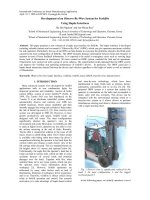
Figure 12: Beacon deployment.
beacons and their visual positions on the map are illustrated by Figure 12. As the shorter broadcast intervals, the more stable BLE signals, we configure it as
small as possible, namely 100 ms.
Deployment
The experiments are conducted on the 4th floor of
Bach Khoa Dormitory, 497 Hoa Hao Street, District
10, Ho Chi Minh City, Vietnam. The area under testing is a half of the floor with dimensions of 26.55 m
x 33.06 m and is shown in Figure 12. The area includes 9 rooms, 1 exit illustrated by their labels and
2 corridors. The dimensions of the vertical and horizontal corridors are 2m x 16.74m and 15.77m x 5.52m
respectively. Blue shapes represent the beacons, and
they are stuck on the walls and 1.2m above the ground.
The device involved in these experiments was Samsung Galaxy Note 5.
In this phase, we conducted some measurements
to evaluate our system performance and accuracy.
RSSId0 , n, Eare the three most important parameters
of the MiRingLA. In our test, as can be seen in Figure 7, RSSId0 is−59dBm To find out the value of n, we
take several RSSI measurements at different distances
d, then compute their corresponding path loss exponents using Equation (3). The final value of n can be
obtained by averaging those computed path loss exponents which are summarized in Table 2. After pos-
53
sessing RSSId0 , n we perform estimation using this
equation:
d = 10
−59 − RSSI (d)
10x2.295
(14)
In the next step, doing the same measurements as
above, and then we compute estimated distances using Equation (14). The environment error E is the difference between an actual and estimated distance. E is
0.57m and shown in details in table III. Equation (5)
gets:
{
Rin = Rave − 0.57
(15)
Rout = Rave + 0.57
and will be used to draw a ring for each beacon
whereRin , Rout , Rave are respectively the inner, outer
radius and the average distance estimated using Equation (14).
Evaluation and Discussion
Figure 13 shows the trajectories of an experiment. We
walk along the lines connecting dots at normal speed,
each step takes about 60 cm and is marked as a dot.
The stars and their line connectors represent the estimated positions and estimated walking path respectively. The positioning error is the Euclidean distance
Science & Technology Development Journal – Engineering and Technology, 2(1):86-99
Table 1: BEACON CONFIGURATION
No.
Major
Minor
Tx (dBm)
Broadcast Interval (ms)
1-6
421
1-6
0
100
UUID = B9407F30-F5F8-466E-AFF9-25556B57FE6D
Table 2: PATH LOSS EXPONENT n
RSSId (dBm)
d(m)
n
RSSId (dBm)
d(m)
n
-52
0.25
1.16
-74
4.00
3.52
-55
0.50
1.33
-76
5.00
3.56
-59
1.00
1.00
-77
6.00
3.16
-61
1.25
2.06
-79
7.10
3.15
-64
1.5
2.84
-80
8.20
3.08
-67
2.00
2.66
-81
9.10
2.96
-74
2.50
3.77
-84
10.1
2.41
-73
3.00
2.93
-86
13.6
2.38
=
n = 2.295
between the user’s true physical position and the estimated one. In this scenario, our proposed approach
achieves the mean localization accuracy of 0.91 m.
When m is set to 100, the average execution time of
MiRingLA on our phone is 112 ms, and the smaller
the value of m, the less computation time. Each time
of finding a route takes around 10 ms. The values
show that our application can provide a position in
each step.
Figure 14 denotes a patient’s schedule including the
information of room, doctor, turn, specialty, and his
status. The route from the current position to the destination is depicted in Figure 15. It consists of some
short parts along with their distances. Moreover, the
application is able to find a route not only within a
floor but from the current position to a location on
another floor. This thanks to the automatic area detection which makes our application context awareness, especially when patients move to another area
or the destination is not in the same area.
Table 4 provides the localization accuracy of some approaches. The author of the study 6 presented a framework tested in an office zone. By applying a combination of PDR and a particle filter, they attained the
accuracy of 1.2m. Given the same area, their method
is fairly effective than ours in terms of the number of
iBeacons, however, it is less accurate and more complicated. The author of the study 7 established an inroom newborns localization system in hospitals with
some deployment patterns and numbers of iBeacons.
They led to the conclusion that 5 iBeacons in the middle area performed best with the mean accuracy of
1.29m. They also compared the performance of the
reality path-loss model and Estimote iBeacon model
by the cumulative distribution function of distance
measurement error. However, their system achieved
less accuracy than ours, their path-loss model may
work only in light-of-sight situations, and no promise
that the model would work in a real hospital have
been given. In 19 the authors applied iRingLA and
performed experiments in an empty 4m-by-4m room
which yielded the accuracy of 0.41m when it comes
to the distance measurement error. However, a small
empty room is an ideal place without obstacles, walls,
furniture, and they did not guarantee their approach
would perform as-is in larger and more complex areas
like ours. In our work, the contribution of the Kalman
filter and MiRingLA method helped together enhance
the overall performance of the system. The real experimental results 20 conducted in our test-bed (section
deployment) show that the methodology is simple but
effective and useful, the accuracy is 0.91 m which is
reliable enough to locate patients and providing navigation.
CONCLUSION AND FUTURE WORK
In this paper, we have introduced a Bluetooth Low
Energy-based Hospital Positioning System made up
of 3 parts: a web server, smartphones, and BLE beacons. The system provides new medical examination
54
Science & Technology Development Journal – Engineering and Technology, 2(1):86-99
Table 3: ENVIRONMENT ERROR
dactual (m)
dMiRingLA (m)
E (m)
dactual (m)
dMiRingLA (m)
E (m)
0.25
0.395
0.145
3.00
3.684
0.684
0.50
0.606
0.106
4.00
4.633
0.633
0.80
1.00
0.2
5.00
4.203
0.797
1.70
2.018
0.318
6.00
6.826
0.826
2.00
2.218
0.218
7.00
6.084
0.916
2.55
2.927
0.377
8.00
8.943
0.943
9.00
10.25
1.25
=
E = 0.57
Figure 13: The trajectories of a specific experiment. The line connecting dots represents the walking path of a
user at normal speed, each step takes 60cm and is marked as a dot. The stars and their line connectors represent
the estimated positions and estimated walking
path respectively
Table 4: THE MEAN ERRORS OF DIFFERENT SYSTEMS
Study
Environment
Method
Error
5
47.3mx15.9m office zone
PDR, particle filter
1.2m
6
a room, 5 iBeacons
Triangulation, LSQ
1.29m
7
a 4m x 4m empty room
iRingLA
0.41m (1D error)
Proposed
corridors of a dormitory’s floor
Kalman filter, MiRingLA
0.91m
55
Science & Technology Development Journal – Engineering and Technology, 2(1):86-99
Figure 14: IPSHApp displays a patient’s schedule including the information of room, doctor, specialty, turn,
and status.
registrations, treatments, in-app schedule management, and navigation. We also proposed a positioning method, MiRingLA, which is a combination of iRingLA and Least Square Estimation, which yielded the
accuracy of 0.91m. Furthermore, a Kalman filter is
also applied to improve the reliability of RSSIs. The
navigation is developed based on the Dijkstra algorithm getting along with automatic current area detection, which provides multi-floor navigation.
The big advantage of our proposed system is effortless
deployments which are an ideal solution to the practice. The beacons are small, long-lasting and easy to
be stuck on walls and relocate, which gives mobility.
Besides, by applying MiRingLA, there are no longer
needs for measurements and calculations for the parameters in the same environment when the deployments are changed.
Some improvements are intended to be conducted
in the future. We are researching on improving the
stability of patients’ positions on moving by utilizing a particle filter along with compass, accelerometer
and gyroscope sensors integrated in available modern phones. For navigation, current routes are fairly
tough and broken due to the lack of dots in Figure 12 and the positions of them. We will define
more points and apply other algorithms. Besides, IPSHApp is mainly tested on a Samsung mobile phone.
Some experiments on Nokia3 carried out show that
the parameters RSSId0 , n, Ehave small differences
compared to the Galaxy Note5 which proved that the
accuracy slightly varied. Instead of using the same
MiRingLA’s parameters for all sorts of smartphones,
we divide them into groups based on their models and
the application will get their corresponding parameters from the server on starting.
LIST OF ACRONYMS
GPS: Global Positioning System
UWB: Ultra-Wide Band
BLE: Bluetooth Low Energy
RFID: Radio Frequency Identification
56
Science & Technology Development Journal – Engineering and Technology, 2(1):86-99
Figure 15: IPSHApp displays the patient’s current position and the route from the current position to the
destination.
PDR: Pedestrian Dead Reckoning
LSQ: Least Squares Estimation
IPSHApp: Android Application
RSSI: Received Signal Strength Indicator
MVC: Model View Controller
WLAN: Wireless Local Area Network
IRingLA: inter Ring Localization Algorithm
MiRingLA: Modified inter Ring Localization Algorithm
CONFLICTS OF INTEREST
The authors declare that there is no conflict of interest
regarding the publication of this article.
AUTHORS’ CONTRIBUTIONS
Phuong Le Van Hoang conducted the theoretical
study, worked out almost all of the technical work including implementing the algorithm, web server, and
Android application; devised experiment scenarios,
performed experiments, and wrote the manuscript
in consultation with Vinh Truong Quang. Vinh
57
Truong Quang thought up conceptual ideas, involved
in planning and supervised the work, contributed to
the design of the system architecture, and the final
manuscript. All authors discussed the results, provided comments and helped shape the research, analysis, and manuscript.
ACKNOWLEDGMENTS
The paper was submitted on February 27, 2019. This
research is funded by Vietnam National University
Ho Chi Minh City (VNU-HCM) under grant number
“C2018-20-14”.
REFERENCES
1. Townsend K, Cufí C, Akiba A, Davidson R. Getting Started with
Bluetooth Low Energy. 1st ed. Sebastopol, CA, USA: OReilly
Media; 2014.
2. Pritt N. Indoor Location with Wi-Fi Fingerprinting. In: IEEE
Applied Imagery Pattern Recognition Workshop: Sensing for
Control and Augmentation (AIPR 2013). IEEE; 2013. p. 1–8.
3. Saab SS, Nakad ZS. A Standalone RFID Indoor Positioning System Using Passive Tags. IEEE Trans Ind Appl. 2010;58(5):1961–
70.
Science & Technology Development Journal – Engineering and Technology, 2(1):86-99
4. Artunç TC, Yalçin ME. Design of an UWB-based indoor positioning system. In: 26th Signal Processing and Communications Applications Conference (SIU). IEEE; 2018.
5. Apple Developer [Internet]. San Jose, CA: Apple Inc. iBeacon –
Apple Developer; [cited 2019 Feb 20]. Available from: https://
developer.apple.com/ibeacon/.
6. Chen Z, Zhu Q, Jiang H, Soh YC. Indoor Localization Using
Smartphone Sensors and iBeacons. In: IEEE 10th Conference
on Industrial Electronics and Applications (ICIEA). IEEE; 2015.
7. Li Z, Yang Y, Pahlavan K. Using iBeacon for Newborns Localization in Hospitals. In: 10th International Symposium
on Medical Information and Communication Technology (ISMICT). IEEE; 2016.
8. Rappaport TS. Wireless Communications: Principles and Practice. In: . vol. 736. Prentice Hall; 2002. 2nd ed.
9. Bertoni HL. Radio Propagation for Modern Wireless Systems.
Upper Saddle River, N.J: Prentice-Hall; 2000. p. 276.
10. Goldsmith A. Wireless Communications. vol. 674. Cambridge
University Press; 2005.
11. Kuo YT, Liao JK, Chiang KW. Accuracy Analysis of Differential Distance Correction Using Bluetooth Low Energy Technology on Indoor Positioning System. In: Proceedings of GSDI 15
World Conference; 2016.
12. Dalce R. Méthodes de localisation par le signal de communication dans les réseaux de capteurs sans fil en intérieur [dissertation]. Toulouse, France; 2013. INSA; .
13. Dalce R, Bossche AVD, Val T. An experimental performance
study of an original ranging protocol based on an IEEE
802.15.4a UWB testbed. In: IEEE International Conference on
Ultra-WideBand (ICUWB). IEEE; 2014.
14. Dalce R, Bossche AVD, Val T. Indoor Self-Localization in a WSN.
In: Propositions and Demonstrator. International Conference
on Indoor Positioning and Indoor Navigation. IEEE; 2013.
15. Geer SVD. Least Squares Estimation. In: Everitt B, Howell DC,
et al., editors. Encyclopedia of Statistics in Behavioral Science.
John Wiley & Sons; 2005. p. 1041–1045.
16. Bulten W, Rossum CV, Haselager FG. Human SLAM, Indoor
Localisation of Devices and Users. In: IEEE First International
Conference on Internet-of-Things Design and Implementation (IoTDI). IEEE; 2016. p. 211–222.
17. Singal P, Chhillar RS. Dijkstra Shortest Path Algorithm using
Global Position System. Int J Comput Appl. 2014;101(6):12–
20.
18. Estimote [Internet]. United States: Estimote. Estimote products; [cited 2019 Feb 27]; [about 7 screens]. Available from: ht
tps://estimote.com/products/.
19. Thaljaoui A, Val T, Nasri N, Brulin D. BLE Localization using RSSI
Measurements and iRingLA. In: IEEE International Conference
on Industrial Technology (ICIT). IEEE; 2015. p. 2178–2183.
20. Home – Dropbox [Internet]. [place unknown]: Dropbox. BLEbased Indoor Positioning System for Hospitals using MiRingLA Algorithm - Dropbox; 2019 Feb 20 [cited 2019 Feb 27].
Available from: 2019.
58
Tạp chí Phát triển Khoa học và Công nghệ – Kĩ thuật và Công nghệ, 2(1):86-99
Bài Nghiên cứu
Hệ thống định vị trong nhà trên nền tảng BLE sử dụng phương
pháp định vị MiRingLA
Lê Văn Hoàng Phương, Trương Quang Vinh*
TÓM TẮT
Trong những năm gần đây, việc bệnh nhân biết mình đang ở đâu và đi như thế nào để đến các
phòng khám trong một bệnh viện lớn đã và đang thu hút sự quan tâm của công chúng. Nhiều
nỗ lực và giải pháp dựa vào con người đã được đưa ra để giải quyết sự khó khăn trong định vị
và tìm đường đi ở các bệnh viện lớn. Tuy nhiên sự khó khăn ấy vẫn đang tiếp diễn, điều đó thúc
giục con người phải xem xét đến yếu tố công nghệ một cách nghiêm túc. Trong bối cảnh này,
hệ thống định vị trong nhà sẽ giúp ích, nó không chỉ đáp ứng được nhu cầu trên mà còn là nền
tảng công nghệ đầy tiềm năng để xây dựng các ứng dụng hữu ích khác. Tuy nhiên, sự thay đổi
liên tục của môi trường bệnh viện và sự phụ thuộc đáng kể vào giai đoạn lắp đặt hệ thống khiến
cho nhiều hệ thống định vị hiện đại khó được áp dụng vào thực tiễn. Trong bài báo này, chúng tôi
trình bày một hệ thống định vị trong nhà dựa trên Bluetooth Low Energy áp dụng cho các bệnh
viện, dễ triển khai, thích ứng cao trong môi trường nhiều nhiễu, nhiều chướng ngại vật. Hệ thống
này có 3 chức năng chính: đăng ký khám bệnh, bệnh nhân quản lý lịch trình khám bệnh trên điện
thoại và chỉ đường cho bệnh nhân đến các phòng ban. Để thực hiện được chức năng đăng ký
khám bệnh, chúng tôi đã xây dựng một ứng dụng web, bên cạnh đó, một ứng dụng Android được
phát triển nhằm hiện thực 2 chức năng còn lại. Chúng tôi đề xuất một phương pháp định vị dựa
trên phương pháp iRingLA, gọi là MiRingLA. Nó là sự kết hợp của 3 vành khăn và phương pháp
xấp xỉ bình phương tối thiểu để khắc phục nhược điểm của phương pháp iRingLA. Ngoài ra, bộ
lọc Kalman được sử dụng để giảm bớt nhiễu cho tín hiệu nhận được. Phương pháp này được thử
nghiệm trong môi trường thực tế và đạt độ chính xác 0.91m. Hơn nữa, chúng tôi thực hiện phép
so sánh để thấy sự tương quan giữa phương pháp được đề xuất và một số phương pháp khác.
Những thí nghiệm được thực hiện đã chứng minh rằng hệ thống này khả thi và phù hợp với một
ứng dụng thực tế.
Từ khoá: Hệ thống định vị trong nhà, Bluetooth năng lượng thấp, giải thuật iRingLA, giao thức
iBeacon, chỉ số cường độ tín hiệu nhận được
Trường Đại học Bách Khoa,
ĐHQG-HCM
Liên hệ
Trương Quang Vinh, Trường Đại học Bách
Khoa, ĐHQG-HCM
Email:
Lịch sử
• Ngày nhận: 27-02-2019
• Ngày chấp nhận: 10-4-2019
• Ngày đăng: 20-8-2019
DOI :
Bản quyền
© ĐHQG Tp.HCM. Đây là bài báo công bố
mở được phát hành theo các điều khoản của
the Creative Commons Attribution 4.0
International license.
Trích dẫn bài báo này: Phương L V H, Vinh T Q. Hệ thống định vị trong nhà trên nền tảng BLE sử
dụng phương pháp định vị MiRingLA. Sci. Tech. Dev. J. - Eng. Tech.; 2(1):86-99.
59