A review of available design techniques and numerical analysis of piled embankment with Geosynthetic
Bạn đang xem bản rút gọn của tài liệu. Xem và tải ngay bản đầy đủ của tài liệu tại đây (593.04 KB, 9 trang )
BÀI BÁO KHOA H C
A REVIEW OF AVAILABLE DESIGN TECHNIQUES AND NUMERICAL
ANALYSIS OF PILED EMBANKMENT WITH GEOSYNTHETIC
Tuan A. Pham1,2 , Pascal Villard1, Daniel Dias1
Abstract: Piled embankment reinforced geosynthetics are used as integrated foundation systems
for construction of embankment over soft ground. Several design guidelines are available in the
literature for these embankments based on the soil arching and tensioned membrane theories.
However, among design engineers, there is uncertainty regarding the applicability of these design
methods. This paper investigates some practical aspects and identifies some inconsistencies in
applying these design methods. Discrete element method with the most advanced code description
currently used for analysis of problems and compared to the available design techniques from the
case study. This comparison allows giving recommendations about selecting the most suitable
design method corresponding to detailed items. According to results, methods of Van Eekelen and
EBGEO are the design methods recommended highly for prediction of stress reduction ratio, while
methods proposed by Abusharar et al. and EBGEO are more suitable for the design of geosynthetic
reinforcement.
Keywords: Piled embankment, geosynthetics, available design methods, discrete element method,
deformation, critical height.
1. INTRODUCTION1
stresses within the soil between piles are
Embankments constructed over soft soils
redistributed as the soil tries to establish
induce a significant load over a large area. The
equilibrium by transferring loads into stiffer
technique of reinforcing soil with columns has
elements and decrease loads on soft ground. As
proven to be an interesting solution that
a result, different structural arrangements of the
prevents failure or excessive deformations of
particles
embankments. A piled embankment reinforced
arrangement and stress redistribution are such
geosynthetic is a complex system consisting of
that the resistance provided by the soil is
piles, generally arranged in a square or
analogous to a structural arch. This is called soil
rectangular pattern and driven into the soft
arching.
are
created.
Sometimes
this
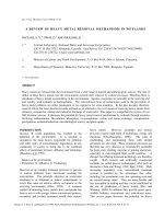
ground to a firm-bearing stratum, Figure 1.
Geosynthetic reinforcement is installed over the
pile caps at or close to the base of the
embankment. Due to the significant difference
in stiffness between the piles and soft soils, the
1
Lab 3SR, University of Grenoble Alpes, Grenoble, France
University of Science and Technology, The University of
Danang, Vietnam
2
132
KHOA H C K THU T TH Y L I VÀ MÔI TR
NG - S 60 (3/2018)
Figure 1. Load transfer mechanism in reinforced
piled embankments (Van Eekelen et al.,2013)
A number of research studies have been
carried out using experimental and numerical
modelling to investigate the behaviour of
piled embankment reinforced geosynthetic
(PERG) ( e.g. Low et al., 1994; Giroud, 1995;
Abusharar et al., 2009; P. Villard, 2009; Van
Eekelen et al., 2014; Joe A. Sloan, 2012). It
has been found that the loads generated in the
geosynthetic
reinforcement
in
piled
embankments are due to two mechanisms.
Firstly, the reinforcement acts to transfer the
vertical embankment load not supported by
the embankment arch to the pile caps.
Secondly, the geosynthetic reinforcement
counteracts the horizontal outward thrust of
the embankment fill. The load due to arching
occurs both along the length and across the
width of the embankment. The load due to
horizontal outward thrust across the width of
the embankment only.
While several methods currently exist for
estimating the magnitude of arching
(Terzaghi, 1943; Guido et al., 1987; BS8006,
2010; Collin, 2007; Hewett and Randolph,
1998; PWRC, 1997; Kempfert et al., 2004;
Abusharar et al., 2009; Low et al., 1994; Van
Eekelen et al., 2014) none yet captures the
essential characteristics of these complex
structures. Also, most of them have not
considered the support of the soft ground in
the load transfer mechanism. The shape of the
arch and its evolution are not consistent with
these guidelines.
This paper aims to investigate a valued
design method for the analysis and design of the
piled embankment reinforced geosynthetic. A
KHOA H C K THU T TH Y L I VÀ MÔI TR
review of existing design techniques (new and
recently revised design methods), that will help
engineers and designers access more
comfortable in practical works. In addition, the
discrete element method, an effective approach
was used in numerical modelling program to
support the comparison, which was not
previously
modeled.
Moreover,
the
inconsistencies in results of the current hand's
methods are identified and discussed in detail.
While the debation and disagree continually
between researchers on the selection of the best
method of the available existing design
techniques for design, there detailed discussions
provide a great insight to clarify and answer
three questions: What popular design methods
are existing? What are the advantages and
disadvantages of each method? Moreover, what
methods should be chosen for the design?
2. NUMERICAL MODELLING BY
DISCRETE ELEMENT METHOD (DEM)
2.1. Discrete element method
Discrete element methods comprise a set of
computational modeling techniques suitable for
the simulation of the dynamic behavior of a
collection of multiple rigid or deformable,
particles or domains of arbitrary shape, subject
to continuously varying constraints. Bodies
collide with one another, new contacts are
established, while old contacts may be released,
giving rise to changes in the contact status and
contact interaction forces, which in turn
influences the subsequent movements of bodies.
The discrete element method used is a threedimensional software (SDEC) based on the
dynamic molecular which apply the Newtonian
approach for each particular particle, through
using rigid bodies (Donze and Magnier, 1995,
1997). The basic element employed are
spherical particles of various sizes which can
interact together. The algorithm of calculation
used consists in successively alternating the
application of Newton's second law.
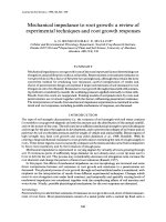
2.2. Discrete element modeling of the problem
Because of the symmetric condition, only a
quarter mesh was modeled to reduce time-
NG - S 60 (3/2018)
133
consuming calculation in this study. An
illustrative example of piled embankment
reinforced geosynthetic is shown in Fig. 2. For a
control case, pile spacing is installed 3m, the
width of pile cap equals 0.6m, the embankment
height is 3m.
2.3. Modeling of the soft ground
The compressible subsoil under the
geosynthetic sheet is assumed to be very weak.
And the action of underlying soil was modeled by
using a Winkler's Spring Model (1867)(springs of
rigidity k are positioned under the sheet). A
compressive modulus of the soft soil is taken into
account to simulate the reaction of the subgrade
soil. For an element of the spring of a section S,
the coefficient K is defined by K=EoedS/D, with
Eoed is the geometric modulus of the soft soil and
D is the thickness of the compressible soil.
2.4. Modeling of the geosynthetics
The geosynthetic sheet is a non-woven
geotextile (modeled by 16 directions of fibers)
with an overall stiffness J = 3000kN/m
reinforced in two perpendicular directions. The
friction angle of the interface soil/geosynthetic
is 260. The sheet is modeled by 1800 three node
finite elements of a thickness e = 5mm.
2.5. Modeling of the embankment material
The embankment is modeled by discrete
element (8000 particles per m3). The particles
shape is given in Fig. 2. The vertical interfaces
between pile-soil-geosynthetics were modeled
to take into account the friction between pile
and embankment materials. The mechanical
properties of interfaces have the similarity to
mechanical properties of embankment clusters.
2.6. Modeling of the structure element
According to J. Han et al. (2002) showed that
as the Young modulus (Ep) of the pile is higher
than 1000Mpa corresponding to 1356Mpa/m,
the stiffness of the pile will not have an effect
on the settlement and load transfer. To eliminate
the effect of pile stiffness, a value 2000Mpa/m
was chosen for all cases.
2.7. Interface behavior and boundary
condition
Specific interaction laws are used to
characterize the interface behavior between the
134
soil particles and the sheet elements. The main
contact parameters are the normal rigidity, the
tangential rigidity, and the friction angle. In
order to rather than the absence of relative
roughness between the sheet elements and the
soil particles, the microscopic friction angle of
contact between exactly to the macroscopic
friction angle given by the model.
The boundary conditions include four
frictionless vertical rigid walls to fix the
horizontal displacement because of the
symmetric condition. A simulation image is
shown in Figure 2.
Figure 2. Numerical modeling of problem by
discrete element method
All parameters of materials used in the
analysis of a control case are listed in Table 1.
where φp is the peak friction angle, n is the
porosity, γ is the unit weight, rg is the radius of
grains, Ks is the subgrade reaction, Kp is the
stiffness of pile, J is the tensile stiffness, e is the
thickness, ν is the Poisson ratio.
Table 1. Material parameters for a control
case
Embankment materials: φp = 400, n =
0.4, γ =18kN/m3, rg =0.04m
Soft soil
Ks = 0.2Mpa,
Pile
Ep = 1500Mpa,
ν =0.25
Geosynthetics
J = EA
=3000kN/m, e = 5mm, ν =0.35
3.
REVIEW
OF
CURRENTLY
AVAILABLE DESIGN METHODS
There are various methods available for the
design of GRPS embankments. Not all these
methods were initially developed for designing
KHOA H C K THU T TH Y L I VÀ MÔI TR
NG - S 60 (3/2018)
embankments, but they were later adopted for
this process. This section presents a description
of currently available design methods.
3.1. Estimation of stress reduction ratio
3.1.1. Adapted Guido Method
The last expression for the stress reduction
ratio included in Russell and Pierpoint (1977) is
commonly referred as the adapted Guido
Method.
(1)
S3 D = 2 (s − a ) / 3H
3.1.3. British Standard BS 8006 (2010)
In this design code, two different arching
conditions are defined: (i) the partial arching
condition, where 0.7(s-a) ≤ H ≤ 1.4(s-a) and (ii)
the full arching reduction, where H >1.4(s-a).
Equations for the stress reduction ratio can be
derived for both conditions using the method
adopted by Russell and Pierpoint (1997).
For partial arching:
S3D = 2s[s 2 − a 2 (Pc / γH )] /[(s + a )(s 2 − a 2 )] (3)
For full arching:
S 3 D = 2.8 s[ s 2 − a 2 (Pc / γH )] /[ (s + a )2 H ] (4)
where Pc – vertical stress on pile cap, S3D stress reduction ratio
3.1.4. Hewlett and Randolph method (1998)
Hewlett and Randolph (1988) carried out
model tests on a granular embankment fill
material overlying a rectangular grid of pile
caps to investigate the amount of load
transferred to the piles and the foundation soil
due to soil arching. The calculations based on
the semi-spherical arches formed of the fill
material.
In that, s - centerline pile spacing, a - width of
pile cap, H - embankment height
3.1.2. Adapted Terzaghi Method
The arching theory developed by Terzaghi
(1943) based on his classic trap door, is used by
many authors to describe the load transfer
mechanism in a pile-supported an embankment.
tanϕ
−4aHKtanϕ
−4(aHK
2 2
γ s2 − a2
q
s2 −a2 )
S3D =
1− e
+
e (s −a )
(γH + q)4aKtanϕ
γH + q
(2)
where γ - unit weight of embankment fills, K
- coefficient of earth pressure, φ – effective
friction angle, q – surcharge or traffic load
(
)
S 3 D = (1 − a / s )2 (K p −1) 1 − 2 s ( K p − 1) /[ H ( 2 K p − 3] + [ 2(s − a )( K p − 1)] /[ 2 H 2 K p − 3 ]
(
)
(
)
(5)
where K - coefficient of passive earth divided into the volume of the embankment that
acts on the improved ground and the
pressure, S3D - stress reduction ratio
unimproved ground or geosynthetic. The
3.1.5. Japanese PWRC method (1997)
This method was proposed by Miki (1997) expression of the vertical stress, p, on the
for embankments on deep mixing method unimproved ground is:
columns. The total embankment volume is
2
s
π
s s − dc
2
(s − d c ) tan θ (5d c + 4 s ) + (4 − π )
tan θ + 2 − 1 tan θ
96
6
2 2
(6)
p=γ
2
π
d
2
c
(
s −
)
4
where dc – diameter of the column, θ – arching angle (θ=450-φ/2)
3.1.6. Kempfert et al. (EBGEO) method
The Kempfert et al. (2004) method is based
on lower bound plasticity theory, pilot-scale
tests, and numerical analyses. Like the Hewlett
S3D =
1 X
q
2
λ
γ
+
H λ1 + h g λ 2
H
γH 1
KHOA H C K THU T TH Y L I VÀ MÔI TR
(
)
−X
and Randolph (1998) method, this method
considers a hemispherical domed arch between
columns or piles caps. The stress reduction ratio
for this method is shown as follows:
h g2 λ 2
+ h g λ1 +
4
NG - S 60 (3/2018)
−X
(
− λ1 + h g2 λ 2
)
−X
(7)
135
λ1 = (sd − d )2 / 8 ;
λ2 = (sd2 + 2dsd − d 2 ) / 2sd2 ;
hg = s d / 2 for H ≥ sd/2;
(
)
X = d K p − 1 / λ2 sd
hg = H for H ≤ sd/2
where sd – diagonal pile spacing, d – pile diameter, Kp – passive lateral earth pressure, hg –
arching height, q – surcharge, H –embankment height, γ – unit weight of embankment fill
3.1.7 Low et al. method (1994)
Low et al. (1994) developed some equations
and charts to evaluate the tension and mobilized
strain in the geosynthetic reinforcement layer
[
]
and the stress reduction over the foundation soil.
The vertical stress acting on the foundation soil
midway between piles, σs, is
σ s = 0.5γ ( s − a)( K p − a ) /( K p − 2) + [s − a ) / s ]K
p
−1
[γH − 0.5γs(1 + (K
p − 2)
−1
)]
(8)
The estimation of stress reduction ratio can be expressed by the following equation:
(9)
S3 D = (σ s − tEs / D ) / γH
where D – soft soil thickness, Es – elastic modulus of soft soil, t – deflection of geosynthetic
3.1.8. Abusharar et al. method (2009)
Based on the approach of Low et al. (1994),
theoretical analysis for pile embankment was
developed by Abusharar et al., (2009). The main
modification was taking into account the skin
friction mechanism at the soil-geosynthetic
interface. The stress reduction ratio can be
calculated by Eq. (9). The following cubic
equation with β = 4t/(s-a) can be obtained:
aβ 3 + bβ 2 + cβ + d = 0
(10)
a = 32DJ +4(s-a)2Es ; b = 2(s-a)2λ3Estanφ 4(s-a)Dσs;
c = 2(s-a) λ3Dσstanφ + (s-a)2Es; d = -(s-a)Dσs
where σs – vertical stress acting on soft soil, J
– tensile stiffness of geosynthetic, λ3interaction factor, φ – effective friction angle of
the surrounding soils.
3.1.9. Van Eekelen et al. method (2014)
A new calculation model is derived and
summarised by Van Eekelen et al. (2013, 2014).
This model is a concentric arch model with the
assumption that the load is transferred along the
concentric 3D hemispheres towards the GR
strips and then via the concentric 2D arches
towards the pile caps. This method is applied to
calculate
soil
arching
as
follows:
A = F pile = (γH + p ).s x .s y − FGRsquare − FGRstrip
(11)
The total load resting on GR + subsoil is,
therefore:
(12)
B + C = FGRsquare + FGRstrip
136
where, FGRsquare – total vertical load applied
exerted by 3D hemispheres, FGRstrip – total
vertical load on GR trips, sx, sy – center-tocenter spacing in both directions.
3.2. Estimation of tension in geosynthetic
The tension in the geosynthetic, T, is
calculated according to,
p.(s 2 − a 2 )
1
1+
(13)
4a
6ε
where, p – pressure distributed on
geosynthetic, ε – a strain of geosynthetic
This equation was used to calculate the
reinforcement tension for the Hewlett and
Randolph, Guido, Terzaghi, Van Eekelen and
BS8006 methods. A design strain of 5% was
used for the calculation, as recommended by
BS8006 (2010).
McGuire and Filz (2008) present a solution
which imposes stress-strain compatibility by
substituting ε=T/J into Equation (13), resulting
in the square column as follow:
96T 3 − 6 K g2T − K g2 J = 0
T=
where
K g = p(s 2 − a 2 ) / a
(14)
According to Nordic guideline (2005), the
tension in geosynthetic due to vertical load in
three dimensional can be determined by
1 + s / a (s − a)2
1
Trp 3D =
.
.γ . 1 +
(15)
0
2
4. tan 15
6ε
where s = pile center to center spacing (m), a
= width of pile cap (m), γ = unit weight of
KHOA H C K THU T TH Y L I VÀ MÔI TR
NG - S 60 (3/2018)
The design methods proposed by Kempfert et
al. that adopted into EBGEO guideline and Van
Eekelen method produces a better match for
numerical results. However, inconsistent results
KHOA H C K THU T TH Y L I VÀ MÔI TR
100
H=1.5m
H=2.25m
H=3m
90
Stress reduction ratio S3D
where t - deflection of geosynthetic, σs –
stress on geosynthetic and soft soils, β = 4t/(s-a)
3.3. Estimation of differential settlement
The maximum mid-pan deflection of the
geosynthetic can be determined by
3
t = (s − a) ε
(17)
8
Eq. (17) is presented in BS8006 (2010) and
Nordic Guideline (2005) in order to calculate
the deflection of the geosynthetic after obtaining
strain value of reinforcement, ε.
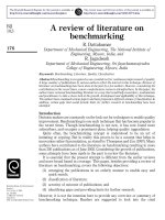
4. ANALYSIS OF RESULTS
4.1. Comparison of results using stress
reduction ratio
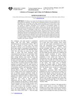
The variation in stress reduction ratio (S3D or
SRR) with embankment height is shown in Fig.
3. To avoid time-consuming, the embankment
height is selected for comparison in this study
because that it is one of the most critical factors
which influence soil arching and tensioned
membrane effect. Out of the nine design
methods, the one proposed by Guido et al.
considerably under-estimate the stress reduction
ratio. Terzaghi's method, BS8006 modified,
Hewlett & Randolph, Low et al. method, and
method adapted by PWRC give overly
conservative results for the stress reduction
ratio, yielding uneconomical designs. The
Abusharar et al. method highly underpredicts
the S3D. The variation in S3D, obtained from this
method shows an inverse variation compared to
the other design methods and numerical results.
This is because the tEs/D term in calculation
equation becomes larger when t is increased
with embankment height.
over the range of embankment height selected.
It has been found that Van Eekelen et al.,
method give the most excellent agreement with
numerical results compared to other remaining
methods. The average difference between these
methods with numerical analysis can be
accepted, approximately 22.6% for EBGEO and
only 1.97% for Van Eekelen method.
80
70
60
50
40
30
20
10
0
1
2
1 - Adapted Guido
6 - Low et al.
3
4
2 - Adapted Terzaghi
7 - Abusharar et al.
5
6
3 - BS8006 modified
8 - EGBO modified
7
8
9
10
4 - Hewle tt&Randolph 5 - PWRC
9 - Van Eekelen
10 - Numerical
Figure 3. Stress reduction ratio with embankment
height
It is better to recall that Van Eekelen method
is one of the newest method currently, which
based on a concentric arch model with the
assumption that the load is transferred along the
concentric 3D hemispheres towards the GR
strips and then via the concentric 2D arches
towards the pile caps. Therefore, this approach
produces more realistic results in practice.
The Van Eekelen et al. method is therefore
strongly recommended for estimation of stress
reduction ratio in the design process. Kempfert
et al. method that adopted into EBGEO can also
be considered as the second selection to predict
the stress reduction ratio.
4.2. Comparison of results using the
differential settlement
40
Differential settlement (cm)
embankment material (m); ε = maximum
allowable strain in the reinforcement
Abusharar et al., (2009) provided a formular
for prediction of tensile force in geosynthetic:
1 + 4β 2
tE
(s − a ) σ s − s
T =
(16)
D
8β
H=1.5m
H=2.25m
H=3m
35
30
25
20
15
10
5
0
Guire1and Filz
2
BS8006
3
Abusharar
4
Van Ee kele
n
5
Numerical-DEM
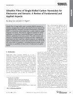
Figure 4. Differential settlement with
embankment height
A comparison of the design methods for
different embankment height using differential
settlement is shown in Fig. 4 with the pile
spacing equals 3m. The differential settlement is
NG - S 60 (3/2018)
137
138
Tension in geosynthetic (kN/m)
which shows the variation in geosynthetic strain
with different embankment heights for the
selected design techniques. The Abusharar are
in better agreement with the numerical results
compared to the other methods. The Van
Eekelen et al. method is under-prediction
significantly, meanwhile, Guire &Filz and
EBGEO is still overestimation of geosynthetic
strain compared to numerical results.
180
H=1.5m
H=2.25m
H=3m
160
140
120
100
80
60
40
20
0
Guire1 & Filz Nordic2Guide
Abusharar
3
EBGEO
4
Van Eekelen
5
Numerical
6
Figure 5. Maximum tension in geosynthetics with
embankment height
7
Strain of geosynthetic (%)
defined as the maximum difference in
settlement between pile and soft ground.
According to the results, the Guire & Filz
method
significantly
over-predict
the
differential settlement. The similar trend can
also be seen in the results of BS8006. The data
show that the BS8006 and Guire & Filz
methods
are
over
conservative
and
uneconomical. It should also be noted that the
method in BS8006 does not have the ability to
assess the influence of embankment height.
In the meanwhile, a method of Van Eekelen
et al. gave the results slightly under-predict
compared to numerical results, up from 5% to
20%. The Abusharar et al. method provides
good agreement with the numerical results for
cases 1.5m and 2.25m. However, for the
Abusharar et al. method, the estimation of
differential settlement is smaller than the
numerical results for the case 3m and this
difference might increase when embankment
height is increased. This can induce instability
or uncertainty for embankment in reality.
4.3. Comparison of results using tension in
geosynthetic
The geosynthetic tension results, obtained
using the selected design techniques, are
compared with the results from present method
and three-dimension numerical model, with the
results plotted in Figure 5. According to the
results, the Guire & Filz method and Nordic
guideline significantly over-predict for all three
cases, it may be even higher when using
BS8006 due to a safety used and adapted into
BS8006, which yielding uneconomical design.
The EBGEO gives an overestimation of the
geosynthetic tension as compared to numerical
analysis (about 48 ÷ 63%). At the meanwhile,
Van Eekelen et al. method produces a
significant under-prediction than the numerical
results (about 38.6 ÷ 51.4%). The Abusharar et
al. method slightly over-estimate (about
18.4 ÷ 38.7%) compared to the numerical
method, but it still agrees better or equally well
with the numerical results.
A similar pattern can be observed in Figure 6
H=1.5m
H=2.25m
H=3m
6
5
4
3
2
1
0
Guire1 and Filz
2
Abusharar
3
EBGEO
4
Van Eekelen
5
Numerical-DEM
Figure 6. Maxium strain of geosynthetics with
embankment height
5. CONCLUSIONS
The design techniques used for comparison
in this paper are the most popular methods used
in practice. According to the results, these
methods differ significantly when predicting the
stress reduction ratio, differential settlement,
strain and tension in geosynthetic.
The methods proposed by Terzaghi, BS8006,
Hewlett & Randolph, PWRC consistently
overestimates the stress reduction ratio, the
methods proposed by Guido, Abusharar,
meanwhile, consistently underpredict the
results. The results obtained from Guido et al.'s
method cannot be relied upon because they only
consider the pile spacing diameter and the
embankment height and no other material
parameters.
Van Eekelen et al. method is highly
KHOA H C K THU T TH Y L I VÀ MÔI TR
NG - S 60 (3/2018)
recommended for selecting to compute stress
reduction ratio. The method presented in
EBGEO guideline might also be considered as
the second choice in the estimation of S3D.
However, Van Eekelen et al. method is still the
best agreement with numerical methods and is
therefore applicable for use in practice.
The Van Eekelen et al. method could be in
better agreement with the numerical results
compared to the other methods in prediction of
stress reduction ratio. However, this method
provides significant underestimation for terms
including differential settlement, strain, and
tension in geosynthetic. It, therefore, is
unrealistic as well as unsafe in the design of
geosynthetic reinforcement.
The Abusharar et al. method gives a better
a = width of pile cap
dc = diameter of column cap
D = thickness of soft soil
Eoed = odometer modulus of soft soil
Ep = stiffness of pile
Es = elastic modulus of soft soil
hg = arching height
H = embankment height
J = tensile stiffness of geosynthetics
Kp = passive earth pressure coefficient
Ks = subgrade reaction coefficient
n = porosity of embankment fills
p = pressure distributed on geosynthetic
Pc
= vertical stress on pile cap
match with a numerical method for prediction of
differential settlement and strain of geosynthetic
while there is significantly overestimation for
tension in geosynthetic. However, the small
strain and deflection of geosynthetic given by
this method cannot be accepted because of the
calculated strain based on the highly
underpredicted stress reduction ratio. The
EBGEO can also be considered the second
choice for prediction of strain and tension in the
geosynthetic.
The critical height of the embankments was
inconsistently suggested overtimes by many
different authors. The numerical results in this
paper show that soil arching can develop
maximum at the ratio 1.25(s-a) and might
decrease after that.
Notation
q
rg
s
sd
S3D
t
T
φ
γ
ν
θ
σs
λ3
ε
= surcharge or traffic load
= radius of grains
= center-to center pile spacing
= diagonal pile spacing
= stress reduction ratio
= deflection of geosynthetics
= maximum tension in geosynthetics
= friction angle of embankment
= unit weight of embankment,
= poisson ratio
= arching angle
= vertical stress acting on soft soil
= interaction factor
= maximum allowable strain
REFERENCES
Abusharar, S.W., Zheng, J.J., Chen, B.G., Yin, J.H., 2009. A simplified method for analysis of a
piled embankment reinforced with geosynthetics. Geotext. Geomembr. 27 (1), 39–52.
Ariyarathne, P., Liyanapathirana, D.S., Leo, C.J., 2013. A comparison of different two-dimensional
idealizations for a geosynthetic reinforced pile- supported an embankment. Int. J. Geomech. 13
(6), 754–768.
BS 8006, 2010. Code of Practice for Strengthened/Reinforced Soils and Other Fills. British
Standard Institution, UK.
Collin, J.G. 2004. Column-supported embankment design considerations. In: Proceedings of the
52nd Annual Geotechnical Engineering Conference. University of Minnesota, Minneapolis,
Minnesota, pp. 51–78.
EBGEO, 2010. Emfehlungen für den Entwurf und die Berechnung von Erdkorpern mit
Bewehrungen aus Geokunststoffen – EBGEO, 2. German Geotechnical Society, Auflage ISBN
978-3-433-02950-3.
KHOA H C K THU T TH Y L I VÀ MÔI TR
NG - S 60 (3/2018)
139
Filz, G.M., Smith, M.E., 2006. Design of Bridging Layers in Geosynthetic- Reinforced ColumnSupported Embankments. Virginia Transportation Research Council, Charlottesville, Virginia, 46.
Guido, V.A, Kneuppel, J.D., Sweeney, M.A., 1987. Plate loading tests on geogrid reinforced earth
slabs (New Orleans). Proc. Geosynthetics 87, 216–225.
Giroud, J. P., Bonaparte, R., Beech, J. F., & Gross, B. A. (1990). Design of soil layer-geosynthetic
systems overlying voids. Geotextiles and Geomembranes, 9(1), 11–50.
Han, J., Gabr, M.A., 2002. Numerical analysis of geosynthetic-reinforced and pile-supported earth
platforms over soft soil. J. Geotech. Geoenviron. Eng. 128 (1), 44–53.
Hewlett, W.J., Randolph, M.F., 1988. Analysis of piled embankments. Ground Eng. 21 (3), 12–18.
Le Hello, B., & Villard, P. (2009). Embankments reinforced by piles and geosynthetics-Numerical
and experimental studies dealing with the transfer of load on the soil embankment. Engineering
Geology, 106(1–2), 78–91.
Sloan, J. (2011). Column-supported embankments: full-scale tests and design recommendations.
Terzaghi, K., 1943. Theoretical Soil Mechanics. Wiley, New York
Van Eekelen, S. J. M., Bezuijen, A., & Van Tol, A. F. (2013). An analytical model for arching in
piled embankments. Geotextiles and Geomembranes, 39, 78-102.
Villard, P., Chevalier, B., Le Hello, B., & Combe, G. (2009). Coupling between finite and discrete
element methods for the modeling of earth structures reinforced by geosynthetic. Computers and
Geotechnics, 36(5), 709–717.
Abstract:
PHÂN TÍCH NỀN ĐẮP ĐƯỢC GIA CỐ HỆ CỌC VÀ LƯỚI ĐỊA KĨ THUẬT:
TỔNG QUAN, PHÂN TÍCH SỐ VÀ TỐI ƯU THIẾT KẾ
Hệ cọc kết hợp gia cường lưới địa kỹ thuật là thường được sử dụng như một hệ móng tích hợp để
gia cố cho nền đắp đi qua các khu vực đất yếu. Một vài phương pháp thiết kế cho kỹ thuật gia cố
này đã được đề xuất bởi một vài tác giả dựa trên nguyên lý của hiệu ứng vòm và lý thuyết màng
căng xảy ra trong nền đắp. Tuy nhiên, kết quả tính toán từ các phương pháp thiết kế cho đến giờ
vẫn tồn tại những sự khác biệt đáng kể, bao gồm cả việc so sánh với kết quả phân tích số và thí
nghiệm. Mục đích chính của bài báo này là để nghiên cứu các khía cạnh thực tế và xác định sự
khác biệt giữa các phương pháp thiết kế tồn tại hiện thời. Mô hình số dựa trên phương pháp phần
tử rời rạc (DEM) cũng được tiến hành trong bài báo này để hỗ trợ cho việc phân tích và so sánh.
Kết quả so sánh giữa các phương pháp lý thuyết và phân tích số đã thể hiện rằng các kết quả từ
phương pháp của Van Eekelen và EBGEO là nhiều hợp lý và phù hợp với kết quả phân tích số so
với các phương pháp khác. Kết quả nghiên cứu cũng chỉ ra rằng hiệu ứng vòm chỉ xảy ra trong
phạm vi chiều cao giới hạn, xấp xỉ bang 1.25 lần khoảng cách giữa hai cọc liên tiếp.
Từ khóa: Nền đắp, hệ cọc gia cường lưới địa kỹ thuật, phương pháp thiết kế, phân tích số, hiệu ứng
vòm, chiều cao tới hạn
Ngày nhận bài:
15/3/2018
Ngày chấp nhận đăng: 28/3/2018
140
KHOA H C K THU T TH Y L I VÀ MÔI TR
NG - S 60 (3/2018)