RobotStudio™ 6.03 graphical programming
Bạn đang xem bản rút gọn của tài liệu. Xem và tải ngay bản đầy đủ của tài liệu tại đây (2.15 MB, 30 trang )
RobotStudio™ 6.03
Graphical Programming
The information in this manual is subject to change without notice and should not be construed as a
commitment by ABB. ABB assumes no responsibility for any errors that may appear in this manual.
Except as may be expressly stated anywhere in this manual, nothing herein shall be construed as any
kind of guarantee or warranty by ABB for losses, damages to persons or property, fitness for a specific
purpose or the like.
In no event shall ABB be liable for incidental or consequential damages arising from use of this manual
and products described herein.
This manual and parts thereof must not be reproduced or copied without ABB's written permission, and
contents thereof must not be imparted to a third party nor be used for any unauthorized purpose.
Contravention will be prosecuted.
Additional copies of this manual may be obtained from ABB at its
then current charge.
© Copyright 2016 ABB All right reserved.
ABB AB
Robotics Products
SE-721 68
Västerås Sweden
2016-06-02 ABB
Table of Contents
1. Graphical programming .............................................................................4
1.1. Creating Curves ................................................................................................. 5
1.2. Creating Paths ................................................................................................... 7
1.3. Target Manipulation ......................................................................................... 12
1.4. Adding Approach and Depart targets ............................................................... 15
1.5. Simulating the robot program ........................................................................... 18
1.6. Collision Detection ........................................................................................... 20
1.7. Reachability...................................................................................................... 24
3
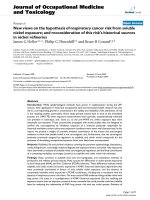
Graphical Programming
1. Graphical programming
Overview
In this module we will learn how to use geometries to automatically create robot paths.
In RobotStudio we can create paths from curves, or by selecting the edge of one or more
surfaces on the geometry.
In the exercises in this module we will create glue paths on a door panel.
Unpack
Use Unpack&Work to open the Pack&Go file GlueStation.rspag from the Courseware >
Stations folder. Unpack it to a new folder myGlueSolution in the Solution > Module_2
folder. You will need to create a Module_2 folder as well. Answer Yes on the Smart
Component question (if it shows).
4
Graphical Programming
These message boxes appear because it includes Smart Components made with Code Behind
in the station.
1.1. Creating Curves
Overview
The two first paths we will create with help of curves. Curves are geometrical objects in the
CAD model, which RobotStudio uses to create paths with targets that follow along the
geometry of an object.
If the curves for the process motions do not exist in the geometry when you import it, you
have several ways of creating curves using the RobotStudio modeling tools. In this exercise
we will use Border Around Surface and Border From Points, two of the three functions for
geometrically creating curves.
Creating a border around a surface
Border around Surface will create curves around all borders on the selected surface.
1. In the Graphics window select Surface Selection.
2. On the Modeling tab click the Border around Surface button.
3. On the door plate select the surface as in the picture below.
5
Graphical Programming
4. Click Create in the Create Border around Surface window.
A new part is created with curves that go along all edges on the selected surface.
Creating a border from points
Border from Points creates a curve that will start and end where you set the first and the last
position, respectively. The position in between is for determining along which edge between
the start and end positions the curve will be created. In this exercise we will create a curve
along one of the arcs on the shape below.
1. Zoom in and set View Center to the shape as in the picture below.
2. On the Modeling tab click the Border from Points button.
3. In the Graphics window click on the body around the shape (see picture on first step).
4. Click out three points as in the picture below. The first point should be at the start of the
arc (use Snap End). The second point should somewhere along the border of the arc (use
Snap Edge). The third should be at the end of the arc (use Snap End).
6
Graphical Programming
5. In the Create Border From Points window click the Create button.
6. Save the station as
\Courseware\Stations\Module_2\myGlueSolution\Stations\myGlueSolution_curves.
1.2. Creating Paths
Overview
In this section we will generate paths using a function called AutoPath. This feature can be
used in a couple of different ways, both of which we will utilize. In the first example we will
use the curves created in the previous section as the basis for some paths. We will also
generate a path directly on the CAD model using this function.
Before creating the paths we will create a workbject.
Creating a workobject from three reference points
1. On the Home tab click the Other button and then select Create Workobject.
2. Name the workobject to wobjFixture.
7
Graphical Programming
3. Define the User Frame with the Three-point method.
4. Click on the top of the three cones marked in the picture below to define the three points.
(Snap Mode: End)
5. Click Accept and then Create to create the workobject. Note that due to the location of
the pin the used to define the y axis, the workobject’s origin will float in “free space” and
will not actually coincide with the position of the first pin.
wobjFixture
8
Graphical Programming
To create paths from curves
1. In the Graphical window select Curve Selection.
2. Select the curve as in the picture below.
3. On the Home tab click on the lower part of the Path button and then select AutoPath.
A preview of the path should now be displayed in the Graphical window, and in the
AutoPath window all surface edges around the path should be displayed. Note that not
all of the selected edges are referenced to the same plane and/or reference surface.
Before creating the path we will select a reference surface.
4. Put the cursor in the Reference Surface field, and then click on the same surface as the
curve was created from (with Border Around Surface).
9
Graphical Programming
5. Change the Approximation Parameters to Circular and the Tolerance to 0,5 mm, then
click Create.
6. In the Paths&Targets browser, rename the new path to GluePath1.
7. Select the path in the Paths&Targets browser, then click on PathTools-Modify, and
then click on Rename Targets. Change Target Prefix to pGluePath1_ and click Apply.
8. Use AutoPath to create a path on the curve created with Border from Points. Use the
surface around the curve as Reference Surface and change the Approximation
10
Graphical Programming
Parameters to Circular and the Tolerance to 0,5 mm .
9. Rename the paths to GluePath2. Give the targets the prefix pGluePath2_ .
Creating path from edges
We will create the last glue path without any curve; instead select the surface edge along the
path. This advantage makes it possible to create a path along multiple surfaces.
1. Zoom and rotate so you have a good view of the marked area in the picture below.
2. Open AutoPath and on the surface selected in the picture below, click close to the edge
closest the robot. The preview of the path should be as in the picture below.
11
Graphical Programming
3. Move the mouse in the right direction along the edge until you see a new preview in the
corner of the door.
4. Click to add that segment to the AutoPath list.
5. Continue like this around the entire door so all segments are added to the AutoPath list.
6. Leave the Approximation Parameters as Linear and set the Tolerance to 0.5 mm, then
click Create.
7. Rename the path to GluePath3. Give the targets the prefix pGluePath3_ .
8. Save the station as
\Courseware\Solutions\Module_2\myGlueSolution\Stations\myGlueSolution_Paths.
1.3. Target Manipulation
Overview
The next step is to offset the targets in the glue paths so the glue is dispensed on the part 4 mm
from the edges of the surfaces. We will also reorient the targets so the robot can reach them
with a minimum of tool reorientation.
Offsetting paths
When AutoPath is used to create a path, the targets will be aligned to the selected surface,
and with the axis defined as Travel Vector (Options-Mechanism) pointing in the path’s travel
direction. This makes it possible to offset the path by moving each target in their local
coordinate system. This however needs to be done before the targets are reoriented.
12
Graphical Programming
1. In the Path&Targets browser expand the node of wobjFixture_of and multi select all
targets belonging to GluePath1.
2. Click on Target Tools-Modify, and then on Offset Position.
3. Move all targets 4mm in Y direction with Reference set to Local, to offset the path from
the edge.
4. Offset GluePaths 2 and 3 the same distance, however be aware that for GluePath2 it
should be in the –Y direction and GluePath3 should be in the +Y direction.
Setting Normal to Surface
In some situations, you may need to adjust some of the generated targets to meet your
requirements. The function Set Normal to Surface is often a useful tool in such cases. Here
we will use View Tool at Target and step through our targets to make sure the Z-orientation
of all targets is pointing in the correct direction. This is important because we will later lock
this axis when aligning the rest of the targets.
1. In Paths&Targets browser, select target pGluePath1_10 and turn on View Tool at
Target with the tool SingleDoser.
2. Step through the following targets and verify that the Z-orientation towards the surface is
OK.
3. Stop when you reach the target below.
4. In the Modify tab, select Set Normal to Surface.
5. Select the surface as below, select Approach Direction –Z and click Apply.
13
Graphical Programming
6. Continue through the remaining targets and make sure no more targets needs to be
adjusted.
Aligning Target Orientation
Now we will rotate the targets around their Z-axis to get a good approach direction for the
robot.
7. Select target pGluePath1_10 and turn on View Tool at Target with the tool
SingleDoser.
8. Verify that the orientation of the tool is as in the picture below. If not, rotate the target
around its Z-axis, so the robot can reach it with a good configuration.
Note!
The resulting orientation of the targets when using AutoPath, depend on the settings in
Options>Mechanism. If other than default settings are used, the result will be different
than shown above.
9. Use Jump To Target to verify that the robot can reach the target.
14
Graphical Programming
10.Multi select all targets (excluding pGluePath1_10) for GluePaths 1, 2 and 3, and then
click on Align Target Orientation on the Target Tools – Modify tab.
11.Select target pGluePath1_10 as Reference and press Apply.
This will align the X-axes of all targets according to the reference target. This is done
without moving the Z-axes.
12.Use View Robot at Target to verify that all targets are reachable. Then turn off View
Robot at Target.
9. Save the station as
\Courseware\Solutions\Module_2\myGlueSolution\Stations\myGlueSolution_Offset_Paths.
1.4. Adding Approach and Depart targets
Overview
The last things we have to do before we can test run our paths is to add approach and depart
targets, set robot axis configurations, and add correct speed and zone data to the move
instructions.
Adding Approach and Depart Targets
1. In the Path&Targets browser, right click on target pGluePath1_10 and select Copy in
the Context Menu.
2. Right click on the workobject wobjFixture and select Paste. A new target is added under
the workobject.
15
Graphical Programming
3. Rename the new target to pApproach_Path1.
4. Use Offset Position to move the new target 100 mm in –Z direction in Reference Local.
5. Use Jump To Target to verify that the target is placed 100 mm above the path.
6. Copy and Paste the last target in GluePath1 and rename the new target to
pDepart_Path1. Offset the target 100 mm in –Z direction.
7. Right click on pApproach_Path1and select Add to path > GluePath1 <First>
8. Do the same for pDepart_Path1 but put it last in the path.
9. Add approach and depart targets for the other glue paths with the same offsets.
Setting robot axis configurations
In many cases the robot may be able to reach a given target in several different ways. In the
pictures below the robot can reach the same target using three completely different axis
configurations.
When a target is taught by jogging the robot to a given position, the axis configuration is
16
Graphical Programming
stored in the target. When targets are created in RobotStudio by one of the geometric tools a
default configuration, which may not be accurate, is used. When using targets created this way
in a program we either have to assign valid robot axis configurations to each target or add a
configuration off instruction to make the robot ignore the missing configuration. In this
exercise we will use the recommended way, which is to set the robot axis configurations for
all targets.
1. In the Path&Targets browser select GluePath1 and then click on Auto Configuration
in the Path Tools – Modify tab.
The Select Robot Configuration window is now displayed in which you set the
configuration for the first target manually. The configuration you select for the first
target might affect the configurations for the following ones.
2. After viewing the configurations, select the configuration with values (-1, -1, -1, 0) and
click the Apply button.
The robot now steps through the path and sets the configuration for each target in the
path. Which configuration to use for each target depends on the previous one, so if the
AutoConfiguration fails, you might get better results with another initial configuration.
Note: If the first target in a given path already has a configuration assigned then Auto
Configuration will use that as a starting point and will not be asked to make a selection.
If you want to change the starting configuration then you must use the Reset
Configurations tool first.
3. Use Auto Configuration to set configurations for the other glue paths. The start
configuration in the paths should be as close as possible to the one selected for
GluePath1.
Modifying Instructions
AutoPath uses the active template to decide what type of move instructions should be
created, and with what speed and zone data. When we created the glue paths, the default
MoveL template was active, which means that the speed data was set to v1000 and the zone to
17
Graphical Programming
z100. These parameters are not likely optimal for a gluing application, so we will change this
data to something more appropriate.
1. In the Path&Targets browser expand GluePath1and select all targets in the path except
for the approach and depart targets.
2. In the Instruction Tools – Modify tab click on Edit Instruction.
3. Change the Speed to v300 and the Zone to z1, and then press Apply.
4. Do the same for the other glue paths.
10. Save the station as
\Courseware\Solutions\Module_2\myGlueSolution\Stations\myGlueSolution_FinalizedPaths.
1.5. Simulating the robot program
Overview
Now we will create a program from the paths by synchronizing the station to Rapid. (the
virtual controller)
NOTE!
Before synchronizing always remember where you are in your synchronization process. Did
you synchronize the changes made in the station to Rapid? Did you make changes in Rapid
that are not in the station? The simulation will run the program as it exists in the virtual
controller so it is important to make sure you are using the correct program information. In
this example you will find that there are already modules existing in the virtual controller
which we will synchronize to.
18
Graphical Programming
Synchronizing the program to the virtual controller
1. On the Rapid tab click the Synchronize to RAPID button.
2. In the Synchronize to Virtual Controller dialog verify that the Modules in the picture
below are selected as target modules. These modules have earlier been used in the station
from the Pack and Go, and are therefore the default selections.
Note: Even if you change the module that the paths sync to the targets for each path will
still sync (according to the default settings) into Module1. This can be changed under
Options>Synchronization.
Setting up and running the simulation
A robot program always has a procedure named main, which is used to arrange and start the
other procedures. When simulating programs in RobotStudio, you create or edit the main
procedure by creating a path named main or doing a procedure manually in the RAPID code.
Let’s do the path one.
1. In Paths&Targets, create an empty path and name it Main.
2. Drag the paths that you want to simulate into Main.
19
Graphical Programming
3. Drag them to modify the order to make sure it’s correct.
4. In the Home tab right click on the system and select Synchronize to RAPID and select
the module in which you would like to create the main procedure in.
5. In the Graphics window click the Play button and verify that the robot moves along all
paths correctly.
6. Save the station as \Courseware\Solutions\Module_2\myGlueSolution\Stations\
myGlueStation_SimulatedPaths.
1.6. Collision Detection
Overview
When watching a simulation in RobotStudio, a collision between two objects is easily
overlooked if the robot moves fast or if the view is not optimal. RobotStudio has the ability to
detect collisions through the use of Collision Sets. Collision Sets give us the ability to
define which objects RobotStudio should watch for collisions between. A Collision Set can
be configured to display a color flash in the graphics window, output a text indication in the
output window and it can even be set to stop the simulation upon collision. In the next
exercise we will create a Collision Set so that we can determine what collisions we have and
then take actions to prevent these collisions.
20
Graphical Programming
To detect collisions
We will now create a collision set with two sets of objects, which RobotStudio will watch for
collisions. Collisions can be both highlighted in the graphics and/or be reported in the output
window.
1.
2.
3.
4.
On the Simulation tab click the Create Collision Set button.
Expand the node of CollisionSet_1.
In the Layout browser drag SingleDoser and drop it on ObjectsA.
Drag the Component Group fixture and workpiece and drop it on ObjectsB.
We have now defined that RobotStudio will detect collisions between A and B.
5. On the Simulation menu, click Play.
We can now see the collisions in both the graphics and in the Output window.
Configuring the collision set
1.
2.
3.
4.
We will now modify the collision set parameters.
In the Layout browser right click CollisionSet_1 and select Modify Collision set.
In the Near Miss (mm) field enter 4.
In the Near Miss Color change to green color.
Click Apply.
Now if we are near a collision the objects will flash green and when a collision occurs
the objects will flash red.
5. On the Simulation menu, click Play.
Avoiding collisions
For the next step we will make some adjustments in order to avoid colliding with the part
however we still want to maintain a set distance (fall within the near miss value) for the
gluing operation.
The tooldata named tNozzle was created on the surface of the dispensing nozzle. The
21
Graphical Programming
targets were created on the top surface of the door panel. This is the reason we have a
series of collisions as the robot follows the paths on the door. To avoid these collisions
(and to perhaps better reflect the actual process with some space for a glue bead) we will
modify the tool data so we have an offset between the tooldata frame and the nozzle tip.
1. In the Path&Targets browser right click on tNozzle and select Set Position in the
Context menu.
2. Move the tooldata 3 mm in +Z direction with Reference set to Local, and press Apply.
3. In the Path&Targets browser we now see that the target configurations no longer are
verified (the yellow triangles). This is because we have moved the tool data used in the
move instructions. The configurations are probably still valid, but to be sure we will
verify this.
22
Graphical Programming
Right Click on GluePath1 and select Configurtions > VerifyConfigurations.
4. Do the same for all other paths in the station.
5. Right click on T_ROB1 and select Synchronize to RAPID in the Context menu.
6. Uncheck the check box for IRB4600_GlueSystem to deselect everything in the
Synchronize to RAPID window.
7. Check the check box for tNozzle and press OK. Now will only the tooldata tNozzle be
synchronized to the RAPID.
8. Run the simulation again to verify that there are no collisions.
9. Save the station as
\Courseware\Solutions\Module_2\myGlueSolution\Stations\myGlueSolution_Collision.
23
Graphical Programming
1.7. Reachability
Overview
In this exercise we will learn how to use the Reachability function. The Reachability
function tests if selected targets are reachable by the robot with the given target orientation.
Prepare
1. Start the Unpack and Work wizard and unpack the station
\Courseware\Stations\Reachability_start.rspag
Testing Reachability
1. On the Home tab in the Paths&Targets browser right click on Path_processes and then
select Reachability.
2. This will bring up the Reachability dialog, where you can see by the red icons that the
majority of the targets in the path not are reachable.
3. Change the Selection Level to Part
4. Freehand move the part by clicking on the Move button and then in Graphics windows
drag the red, green, blue arrows. Notice how the part moves, but the path remains.
24
Graphical Programming
5. On the Quick Access toolbar click the Undo button so that the path & part match again.
6. In the Paths&Targets browser right click on the obWorkpiece workobject then point to
Attach to and select the carfront part.
RobotStudio will now make the workobject dependent on the part, so by moving the part
we move the workobject as well.
7. In the Update position window click the No button.
8. Freehand move the part again. Notice how the targets follow, and how the reachability
will change when the part is within reach. Stop when the path is reachable.
Using Auto Configuration and simulate
1. In the Paths&Targets browser, right click on the Path_processes path and then select
Auto Configuration.
2. Select the first configuration in the Robot Configurations dialog and click the Apply
button.
25