On the role of boride in the structural integrity of a turbine disc superalloy’s solid state weld
Bạn đang xem bản rút gọn của tài liệu. Xem và tải ngay bản đầy đủ của tài liệu tại đây (2 MB, 10 trang )
American Journal of Materials Engineering and Technology, 2017, Vol. 5, No. 1, 14-23
Available online at />©Science and Education Publishing
DOI:10.12691/materials-5-1-3
On the Role of Boride in the Structural Integrity of a
Turbine Disc Superalloy’s Solid State Weld
K.M. Oluwasegun1,*, J.O Olawale1, M.D. Shittu1, O.O. Ige1, P.O. Atanda1, O.O. Ajide2, L.O. Osoba3
1
Department of Materials Science and Engineering, Obafemi Awolowo University, Ile-Ife, Nigeria
2
Department of Mechanical Engineering, University of Ibadan, Nigeria
3
Department of Metallurgical and Materials Engineering, University of Lagos, Nigeria
*Corresponding author:
Abstract This work reports the melting of boride precipitates along the grain boundary of a supposedly solid state
welding of a polycrystalline superalloy, and discusses its attendant effect on the hot ductility behaviour of the alloy.
Nickel-based superalloy used for this study was previously processed by hot extrusion of argon atomized powered
followed by forging. The alloy was solution heat treated at 1120°C, aged at 760°C and subsequently air cooled to
room temperature. Thereafter, it was welded by inertial friction welding (IFW) at a forging pressure of 250 MPa and
finally stressed relieved at 760°C for 8 hours. The microstructures of welded samples were studied by scanning and
scanning transmission electron microscopes. Gleeble hot ductility test was carried out on tensile specimen machined
from the welded sample. The microstructures of the welded alloy shows that boride precipitates liquated along the
grain boundary within the heat affected zone (HAZ) as a result of rapid heating of IFW. The results of hot ductility
test revealed that the melting of boride lowered the hot ductility of the alloy. It was concluded that the boride
precipitates liquated along the grain boundary of the nickel-based superalloy during solid state welding and lowered
its hot ductility.
Keywords: superalloy, solid state welding, boride precipitates, grain boundary, hot ductility, welding
Cite This Article: K.M. Oluwasegun, J.O Olawale, M.D. Shittu, O.O. Ige, P.O. Atanda, O.O. Ajide, and L.O.
Osoba, “On the Role of Boride in the Structural Integrity of a Turbine Disc Superalloy’s Solid State Weld.” American
Journal of Materials Engineering and Technology, vol. 5, no. 1 (2017): 14-23. doi: 10.12691/materials-5-1-3.
1. Introduction
The need for more heat resistant materials in aircraft
engine turbo superchargers prompted the development of
superalloys in 1930s. It has been driven since the early
1940s by the increasing demands of advancing gas turbine
engine technology [1]. In addition to aircraft applications,
superalloys are now used in space vehicles, rocket engines,
nuclear reactors, submarines, steam power plants,
petrochemical equipment and other high-temperature
applications. The largest use of superalloys, however, is
the gas turbine industry [1]. The recent global demand in
the reduction of emissions is also pertinent to aerospace
industry. Achieving this goal of reducing emission by
aerospace industry and consequently lowering its burden
on the environment significantly requires a generation of
jet engines that will burn fuel more effectively at higher
temperature [1]. This stems the need for the development
of new superalloys that offer heat resistance of which
nickel base superalloys are candidate superalloys. Nickelbased superalloys among others have emerged as the
choice for high-temperature application because of their
FCC crystal structure, which confers good toughness and
ductility, due to a considerable cohesive energy arising
from the bonding provided by the outer d electrons [2].
This crystal structure is stable from room temperature to
the melting point, so that there are no phase
transformations leading to expansion and contraction,
which might complicate its use for high temperature
components. Their low rate of thermally activated
processes (e.g. creep) and moderate cost have also
contributed to their choice as candidate materials for high
temperature applications. The high corrosion resistance
observed in these alloys stems from the high level of
chromium, as chromium forms an oxide layer which
protects the material from further oxidation.
Addition of boron to nickel-base superalloys has been
proposed to influence the chemistry and structure of the
grain boundary precipitates [3]. It is generally known that
the solid solubility of boron in austenitic γ alloys is very
low [4]. For example, it was reported that the solubility of
boron in 18%Cr-15%Ni stainless steel was 97 ppm at
1125°C. This solubility decreased rapidly with decreasing
temperature, becoming less than 30 ppm at 900°C [25]. In
addition to this, boron atoms are larger than the common
interstitial elements (e.g carbon) but smaller than
substitutional elements like Co and Cr. This misfit in size
of boron atoms for substitutional and interstitial sites in
austenitic lattices suggests that it could be energetically
favorable for boron atoms to segregate to loosely packed
regions like grain boundaries and incoherent interphase
boundaries [5,6]. Kurban et al [7] have been able to report
recently from their ion mass spectroscopy study of boron
segregation that boron tends to have a stronger affinity for
American Journal of Materials Engineering and Technology
partitioning into second phase particles than for remaining
in solid solution on grain boundaries [7]. Borides are hard
refractory particles observed only at grain boundaries.
They are formed by the reaction of boron with elements
like Cr, Mo and Ti. They vary in shape from blocky to
half-moon or spherical in appearance. This reduces the
onset of grain boundary tearing under rupture loading [1].
Complex-shaped components of superalloys are required
with suitable elevated temperature mechanical properties
and good hot corrosion resistance in order to withstand
the stringent operating conditions encountered in the
hot sections. Unfortunately, cost efficient commercial
application of these materials has been largely restricted
due to the difficulty in joining them by conventional
welding techniques during manufacture and repair. This is
because γ' precipitation hardened nickel-base superalloys
are highly susceptible to heat affected zone (HAZ)
microfissuring during welding and subsequent post weld
heat treatments [8-16]. This connotes that as new and
improved materials are developed to meet the severe high
temperature environment challenge, then the challenge of
welding them becomes even more demanding. To meet
this welding challenge of new generation of high
performance and high temperature superalloys, friction
based solid state welding techniques are fast becoming
industrial method of choice [17]. Inertia friction welding
(IFW), a nominal solid state welding process that has
existed for some time has now been employed in joining
aero engine components since it does not involve any
melting, provided that optimum welding parameters are
chosen [17].
Grain boundary strengthening by the precipitation of
borides is one of the strengthening mechanisms that have
been employed for polycrystalline superalloys. Solid state
welding of these alloys have been reported to proffer
better high temperature mechanical properties than the
conventionally fusion welding techniques based on the
premise that melting is not involved [17]. However, the
behaviour of the boride precipitates during solid state
welding of polycrystalline superalloys has not been duly
studied. Hence, this study.
2. Materials and Method
The material used in this work is a nickel-base
superalloy, which was processed by hot extrusion of argon
atomized powder and followed by forging. The parent
alloy with chemical composition (wt%) 15.0Cr, 18.5Co,
5.0Mo, 3.0Al, 3.6Ti, 2.0Ta, 0.5Hf, 0.015B, 0.06Zr,
0.027C nickel balance, has been solution heat treated at
1120°C for 4 hours and aged at 760°C for 8 hours with
subsequent air cooling, and it is applicable in turbine disc
of aero or land based engine. The alloy was inertia friction
welded at a forging pressure of 250 MPa, an upset of 5.4
mm and 0.79 mm/s linear burn off rate (LIBOR). It was
thereafter subjected to a stress relieved post weld heat
treatment (PWHT) at 760°C for 8 hours and air cooled.
Gleeble hot ductility test was carried out by heating a
tensile specimen to 1300°C at 20°C/s with an applied
constant tensile load of 0.5 kN using a DSI Gleeble
thermomechanical simulation system. Welded samples
were sectioned parallel to the forging axis of the weld and
15
the fractured hot ductility test samples were sectioned
perpendicularly to the fracture surface. Both were
prepared using standard metallographic procedures. An
electrolytic etching using solution of water with a
concentration of 10 % of orthophosphoric acid, at 3.5 V
for 3 seconds was used to reveal the microstructure. This
preferentially dissolves the γ phase leaving the γ' in relief.
The microstructures were studied by an FEI-XL 30 field
emission source scanning electron microscope and a JEOL
2100 scanning transmission electron microscope, each
equipped with oxford instrument energy dispersive X-ray
spectrometers with silicon drift detector (SDD). TEM
samples were prepared by electropolishing technique
using a Struers Tenupol-3 twin-jet electropolisher. The
polishing was done in a solution containing 10%
perchloric acid in 90% methanol at 20 V and -20°C to
obtain transparency to the beam of electrons.
Thermodynamic simulation software (Thermo-Calc)
along with assessed thermodynamic database TTNI7
was also used to study phase transformations in the
multicomponent alloy. This is based on the computation,
via complex thermodynamic descriptions of the various
phases in a given system, of thermodynamic equilibria. A
numerical minimization of the total Gibbs free energy of
the alloy is performed at a given temperature by finding
the optimal partition of elements into different phases and
the optimal amounts of such phases [18]. This makes it
possible to determine the amounts and compositions of the
constituting phases as a function of temperature for a
material of a given composition.
3. Results and Discussion
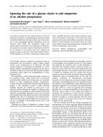
Figure 1a shows an SEM image of the parent alloy’s
microstructure, showing γ' precipitates and spherical
borides. Representative image J output for area fraction
quantification of the borides is presented in Figure 1b.
Figure 1c is a TEM BF image of a typical boride in the
alloy and its TEM EDX spectrum (Figure 1d), illustrating
a significant boron concentration in the phase. The strong
Mo and Cr peaks are characteristic of M3B2 and M5B3
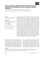
borides. A further step was taken by examining this phase
by TEM SADPs taken along three zone axes (Figure 2).
This shows that they are M3B2 boride with a body centred
tetragonal (bct) crystal structure with lattice parameters
a=5.72 Å and c=3.07 Å. These boride precipitates were
observed along the grain boundaries and their size lay
between 250 nm and 390 nm with ~0.5% area fraction
(Figure 1a, b). Other precipitates like MC carbides and
hafnium oxides were also observed in the parent alloy.
Table 1 shows the result of the chemical analysis of the
observed precipitates within the parent alloy. All analyses
were carried out on a transmission electron microscopy
equipped with silicon drift EDX detector (SDD).
Precipitates with sizes below 50 nm (tertiary γ') were
analyzed by TEM EDX using carbon extraction replicas,
while others were analyzed using conventional thin foil
specimens. The values in the Table 1 represent the average
value for 12 different particles analyzed for each of
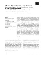
the precipitates. Figure 3 shows the phase fraction
against temperature of different phases calculated by
Thermo-Calc using the nominal chemical composition of
16
American Journal of Materials Engineering and Technology
the alloy. This profile shows that the solvus temperature
of γ' (labelled as 5) is approximately 1155°C, and has been
confirmed experimentally. The thermo-calc result has also
been used to predict the solvus temperature of M3B2
(labelled 6 on the Thermo-Calc profile) and MC carbide
(labelled 3) as 1150°C and 1286°C respectively.
Figure 1. (a) SEM image of alloy ‘X’ showing γ' precipitates and grain boundary borides (insert arrows in ‘a’) (b) representative image J output for
area fraction (%) quantification of boride in ‘a’ (c) TEM BF image of M3B2 boride (d) TEM EDX of M3B2 boride with strong Mo and Cr peaks.
Figure 2. SADPs taken from a boride particle along three zone axes; used to confirm the crystal structure (bct) and lattice parameter of the boride. (b)
A schematic Kikuchi pattern along the three zone axes in ‘a’.
American Journal of Materials Engineering and Technology
17
Figure 3. Thermo-Calc for (a) the nominal composition of the parent alloy, showing phase fraction vs temperature (Note that the predicted phases
labelled 3, 6, 7, 8 and 9 were not observed in this work) (b) the composition of M3B2 boride. It predicts the onset of melting of the boride to be about
1200°C (insert black arrow)
Figure 4. (a) SEM micrographs showing liquated boride along a grain boundary (GB) (b) a micrograph showing liquation products on the same GB
from both boride and γ' precipitates (c) SEM EDX from the liquated boride
American Journal of Materials Engineering and Technology
18
Table 1. Chemical Analysis of Precipitates in the Parent Alloy
Gamma Prime
Element
(Atomic %)
Primary γ’
Secondary γ’
Tertiary γ’
MC
M3B2
AlK
10.14±1.1
13.53±0.4
13.69±0.32
0.0
0.0
HfO2
0.72±0.14
TiK
9.24±0.6
8.12±0.7
8.01±0.62
24.09±1.2
2.19±0.6
0.61±0.17
CrK
4.22±1.4
1.59±0.43
1.41±0.81
3.06±0.4
22.35±0.4
1.43±0.32
CoK
11.54±0.51
7.53±0.52
6.59±1.4
2.21±0.3
3.99±0.2
1.25±0.21
NiK
62.01±1.8
65.42±1.32
67.74±2.14
5.38±0.3
3.18±0.3
7.51±1.03
ZrL
0.17±0.12
0.03±0.01
0.06±0.3
0.47±0.08
0.23±0.06
3.72±0.72
MoL
0.29±0.24
0.78±0.31
1.41±0.62
0.81±0.1
21.54±0.7
0.2±0.03
HfM
0.36±0.14
0.19±0.12
0.05±0.02
3.41±0.32
0.04±0.03
14.3±1.7
TaM
2.03±0.12
1.33±0.4
1.04±0.4
11.2±0.8
0.97±0.2
0.0
CK
0.0
0.0
0.0
49.4±1.4
0.0
0.0
BK
0.0
0.0
0.0
0.0
45.5±1.2
0.96±0.13
OK
0.0
0.0
0.0
0.0
0.0
69.30±2.03
3.1. Microstructure of the Welded Alloy
It has been extensively studied and reported that
primary γ' precipitates constitutionally liquated within the
heat affected zone of different nickel-based superalloys
during different welding techniques [12,13,19,20], thus,
that is not the focus of this paper. In this work, aside from
the primary γ' precipitates that were observed to liquate
constitutionally within the weld heat affected zone, the M3B2
precipitates found in the parent alloy have also been observed
to liquate within the heat affected zone (150-360 μm from
the weld bond line). Figure 4 a is an SEM micrograph showing
liquated boride along a grain boundary. Concurrent liquation
of boride and primary γ' along the same grain boundary
was also observed (Figure 4 b). The SEM EDX spectrum
(Figure 4c) shows B, Cr and Mo peaks which are the main
elements in M3B2. The liquation of M3B2 within the heat
affected zone is evident from morphological point of view
M3B2 in the parent material are spherical) and is also
consistent with the Thermo-Calc results, showing that the
melting of M3B2 could be initiated at about 1200°C. The
solvus temperature of M3B2 (see composition in Table 1)
predicted by Thermo-Calc for the nominal composition of
the parent alloy is approximately 1150°C, (red arrow in
Figure 3a) which is close to the solvus temperature of primary
γ' (1155°C), and thus they could have survived the solvus
temperature and melted by the rapid heat of welding at the
thermodynamically favored temperature of welding. The
maximum temperature reached by a typical inertia friction
welding (similar to present work) of a polycrystalline
superalloys has been modeled and described to be about
1200°C [21].
Further steps were taken to identify the crystal structure
of the liquated boride. Figure 5a is a TEM BF image
of a liquated boride along a decohesed grain boundary.
STEM SDD mapping (Figure 5b) and quantitative results
(Table 2) show this particle to be a Cr and Mo-rich boride.
SADPs (Figure 6) taken from this liquated particle along
two zone axes are consistent with a body centred
tetragonal crystal structure with lattice parameters a = 5.70
Å and c = 3.04 Å, characteristic of M3B2.
Figure 7 shows that within the heat affected zone where
primary γ' and M3B2 liquated, MC carbides were
unaffected by the heat from the welding. Although the
area fraction of MC carbide was less than 1%, they were
still found pinning grain boundaries, and could therefore
prevent significant grain growth in the region. Figure 8
shows another region of the heat affected zone where the
melting of boride was associated with grain boundary
decohesion. The EDX mapping clearly shows that the feature
within the decohesed grain boundary is Cr-Mo and also
shows the presence of boron, which is typical of boride in
the superalloy understudy. An unaffected blocky Ti-Ta-rich
MC carbide is also apparent close to the melted boride in
Figure 8, which corroborates the observation in Figure 7.
3.2. Melting of M3B2 Boride within the HAZ
During rapid heating of IFW, where diffusion time is
limited, dissolution of borides (solvus ~1200°C, refer
to Figure 3) may be delayed until the temperature reaches
a point where borides can thermodynamically melt
(Figure 4, Figure 5, Figure 7 and Figure 8). Also, various
investigators [22,23,24] have reported that the liquation of
boride within the HAZ of fusion welded nickel-based
alloys was due to insufficient time for homogenization by
diffusion of boron during the rapid heating of welding,
which resulted in considerable enrichment of grain
boundary regions with boron (melting point depressant).
According to B-Cr-Mo phase diagram for an M2B type
boride (Figure 9) [27], it is possible that enrichment of
boron in a boride/matrix system can lower the solidus
temperature and thus enhance the melting of the boride. It
may be argued that the observed hole in the micrographs
(Figure 5 and Figure 8) may not be directly linked to the
occurrence of boride liquation in the alloy since it is
possible for some precipitates (e.g MC carbide) to have
fallen out from the site, but it is important to mention that
this type of micro cavity has been observed in other boride
liquated grain boundaries in the same weld. Thus,
sufficient thermal stress/strain due to thermal gradient
during welding could also be a possible cause of the
observed voids due to the decohesion of the weak grain
boundary where boride liquated.
American Journal of Materials Engineering and Technology
Figure 5. (a) STEM BF image of a liquated M3B2 particle and a Hf-rich oxide (b) STEM EDX maps of the liquated phase in ‘a’.
19
20
American Journal of Materials Engineering and Technology
Figure 6. (a) SADP from the liquated boride shown in Figure 5. The bold angle is the total tilt angle while the unbold is the calculated angle. (b)
Schematic Kikuchi pattern along the zones in ‘a’
Figure 7. (a) SEM image of MC carbide within the CLZ (b) TEM DF image of a different intergranular MC carbide within the heat affected zone with
insert SADP (c) SEM EDX spectrum of the MC carbide in ‘a’. MC carbides in this region of the weld are clearly unaffected by the heat of welding.
American Journal of Materials Engineering and Technology
21
Figure 8. (a) STEM BF image of a liquated M3B2 particle associated with unaffected MC carbide and hafnium oxide (b) STEM EDX maps of the
liquated phase in ‘a’.
22
American Journal of Materials Engineering and Technology
Figure 9. B-Cr-Mo phase diagram showing the effect of boron on
increasing the melting temperature range of an M2B boride [25]
3.3. Effect of Melting of Precipitates on the
Hot Ductility of the Alloy
The susceptibility of structural alloys to weld HAZ
microcracking is often quantified by Gleeble hot ductility
testing [26,27]. Thus, in order to validate the effect of
constitutional liquation of grain boundary precipitates
within the HAZ of this alloy during inertia friction
welding, Gleeble hot ductility testing has been employed
in this work. This test is based on the premise that the
deformation behavior of a material, as evaluated by its hot
ductility, reflects its capability to accommodate tensile
stresses and resist cracking during welding [27].
Figure 10 shows stress vs temperature profile of a
Gleeble tensile specimen heated to 1300°C at 20°C/s with
an applied constant tensile load of 0.5 kN. The sample
failed during the test with an abrupt drop in the load at
about 1214°C, which is below the solidus temperature of
the alloy (1243°C) as predicted by Thermo Calc (Figure 3a).
The ductility measured after the material failed was
zero (no change in the diameter of the failed sample). The
temperature at which the material failed is consistent with
the temperature where liquation of precipitates (both γ'
and boride) occurred in the alloy as shown in this work.
The microstructure adjacent to the fracture surface of the
tested sample was examined, and liquation products of
boride and γ' were found to decorate the grain boundary as
shown in the insert of Figure 10. This observation
illustrates that the strength of the alloy could be affected
by the liquation of precipitates within heat affected zone
during welding. The release and diffusion of boron, a
known melting point depressant element by the melting of
boride during the supposedly solid state welding of the
superalloy could worsen the reduction of ductility within
the region and thus the failure of the material.
4. Conclusion
Grain boundary strengthening boride precipitates have
been observed to melt during a supposedly solid state
welding process. This has the propensity of lowering the
hot ductility property of the alloy during welding and
consequentially enhancing decohesion of grain boundaries.
The response of boride to very rapid heating of inertia
friction welding in this work could be similar to other
solid state welding techniques, where M3B2 borides
strengthened polycrystalline superalloys are being welded,
thus adequate attention is required.
Acknowledgement
The authors would like to acknowledge The School of
Metallurgy and Materials of The University of
Birmingham, United Kingdom for the access to the
facilities needed to make this research a success.
References
[1]
[2]
[3]
[4]
Figure 10. Stress and temperature profile during Gleeble on-heating
ductility test of nickel-based superalloy with insert microstructure
observed adjacent to the fractured surface. The arrows on the plot
illustrate the correspondence between the temperature where liquation of
the precipitates occurs and the abrupt drop in stress level
[5]
[6]
W.C. Hagel, The Superalloys, John Wiley & Sons, New York,
1972.
R.C. Reed, The Superalloys, Fundermentals and Applications,
University Press, Cambridge, 2006.
A.F. Padilha, G. Schanz, Precipitation of a boride phase in 15percent-Cr-15-percent-Ni-Mo-Ti-B austenitic stainless-steel (DIN
1.4970), Journal of Nuclear Materials 95 (1980) 229-238.
C. Stocker, M. Zimmermann, H.J. Christ, Z.L. Zhan, C. Cornet,
L.G. Zhao, M.C. Hardy, J. Tong, Microstructural characterisation
and constitutive behaviour of alloy RR1000 under fatigue and
creep-fatigue loading conditions, Material Science and
Engineering A 518 (2009) 27-34.
D.H. Maxwell, J.F. Baldwin, J.F. Radavich, New concept in
superalloy ductility, Metallurgia and Metal Forming 42 (1975) 332.
H.R. Zhang, O.A. Ojo, Cr-rich nanosize precipitates in a standard
heat-treated Inconel 738 superalloy, Philosophical Magazine 90
(2010) 765-782.
American Journal of Materials Engineering and Technology
[7]
[8]
[9]
[10]
[11]
[12]
[13]
[14]
[15]
[16]
[17]
[18]
M. Kurban, U. Erb, K.T. Aust, A grain boundary characterization
study of boron segregation and carbide precipitation in alloy 304
austenitic stainless steel, Scripta Materialia, 54 (2006) 1053-1058.
W.A. Owczarski, D.S. Duvall, C.P. Sullivan, Model for heataffected zone cracking in nickel-base superalloys, Welding
Journal 45 (1966) 145-155.
M. Prager, C.S. Shira, Welding of precipitation-hardening nickelbase alloys, Welding Research Council - Bulletin Series 128 (1968)
55.
M.H. Haakens, J.H.G. Matthey, New approach to the weldability
of nickel-base as-cast and powder metallurgy superalloys,
Welding Journal 61 (1982) 25-30.
T.J. Kelly, Welding metallurgy of investment cast nickel-based
superalloys, Weldability of Materials 1990 151-157.
O.A. Ojo, R.G. Ding, M.C. Chaturvedi, Heat affected zone
microfissuring in a laser beam welded directionally solidified
Ni3Al-base alloy, Scripta Materialia 54 (2006) 2131-2136.
G. Cam, M. Kocak, Progress in joining of advanced materials,
International Materials Reviews 43 (1998) 1-44.
M.B. Henderson, D. Arrell, M. Larsson, G. Marchant, Nickel
based superalloy welding practices for industrial gas turbine
applications, Science and Technology of Welding and Joining 9
(2004) 13-21.
J.K. Tien, T.J. Caulfield, Superalloys, Supercomposites and
Superceramics, Academic Press Inc, London, 1989.
Z.W. Huang, H.Y.Li, M. Preuss, M. Karadge, P. Bowen, S. Bray,
G. Baxter, Inertia friction welding dissimilar nickel-based
superalloys alloy 720Li to IN718, Metallurgical and Materials
Transactions A – Physical Metallurgy and Materials Science 38A
(2007) 1608-1620.
M. Preuss, J.W.L. Pang, P.J. Withers, G.J. Baxter, Inertia welding
nickel-based superalloy: Part II. Residual stress characterization,
Metallurgical and Materials Transactions A: Physical Metallurgy
and Materials Science 33 (2002) 3227-3234.
F. Tancret, Thermo-Calc and Dictra simulation of constitutional
liquation of gamma prime (γ') during welding of Ni base
superalloys, Computational Materials Science 41 (2007) 13-19.
23
[19] K.M. Oluwasegun, J.O. Olawale, O.O. Ige, M.D. Shittu, A.A.
[20]
[21]
[22]
[23]
[24]
[25]
[26]
[27]
Adeleke, B.O. Malomo, Microstructural characterization of
thermomechanical and heat-affected zones of an inertia friction
welded astroloy, Journal of Materials Engineering and
Performance 23 (2014) 2834-2846.
R.K. Sidhu, O.A. Ojo, M.C. Chaturvedi, Microstructural analysis
of laser-beam-welded directionally solidified Inconel 738,
Metallurgical and Materials Transactions A: Physical Metallurgy
and Materials Science 38 (2007) 858-870.
L. Wang, M. Preuss, P.J. Withers, G. Baxter, P. Wilson, Energyinput-based finite-element process modeling of inertia welding,
Metallurgical and Materials Transactions B: Process Metallurgy
and Materials Processing Science 36 (2005) 513-523.
H.A. Shahsavari, A.H. Kokabi, S. Nategh, Effect of preweld
microstructure on HAZ liquation cracking of Rene 80 superalloy,
Materials Science and Technology 23 (2007) 547-555.
R.K. Sidhu, O.A. Ojo, M.C. Chaturvedi, Microstructural response
of directionally solidified Rene 80 superalloy to gas-tungsten arc
welding, Metallurgical and Materials Transactions A: Physical
Metallurgy and Materials Science 40 (2009) 150-162.
O.A. Ojo, N.L. Richards, M.C. Chaturvedi, Study of the fusion
zone and heat affected zone microstructures in tungsten inert
gas-welded INCONEL 738LC superalloy, Metallurgical and
Materials Transactions A – Physical Metallurgy and Materials
Science 37A (2006) 421-433.
P. Villars, A. Prince, H.Okamoto, Handbook of Ternary Alloy
Phase Diagram 5 (1995) 5526.
O.A. Ojo, M.C. Chaturvedi, On the role of liquatedγ' precipitates
in weld heat affected zone microfissuring of a nickel-based
superalloy, Materials Science and Engineering A – Structural
Materials Properties Microstructure and Processing 403 (2005).
77-86.
W. Lin, J.C. Lippold, W.A. Baeslack, An evaluation of heataffected zone liquation cracking susceptibility.1. Development of
a method for quantification, Welding Journal 72 (1993) 135-153.