Control 4DOF tele operation manipulator
Bạn đang xem bản rút gọn của tài liệu. Xem và tải ngay bản đầy đủ của tài liệu tại đây (603.9 KB, 9 trang )
Science & Technology Development, Vol 16, No.K2- 2013
CONTROL 4DOF TELE-OPERATION MANIPULATOR
Tu Diep Cong Thanh
University of Technology, VNU-HCM
(Manuscript Received on April 5th, 2012, Manuscript Revised May 30th, 2013)
ABSTRACT: Tele-operation manipulator (TM) is well-known as thebest solution for interacting
between humans and the unsafe environment such as dangerous, toxic, infectious or sterile.In this study,
a low cost TM system is introduced. In addition, the network control algorithms to overcome
teleoperation are proposed.
KEYWORDS:Tela-operation, Control, LAN
1. INTRODUCTION
explosives detection arm of national defense
Tele-Operation Manipulator (TM) system
and arm on the spacecraft, the main in space
is a remote control manipulator consists of two
[3], hand-picking machine of nuclear fuel in
arms: the master and slave. Slave manipulator
nuclear
will be controlled to perform the same motion
manipulator on the seabed studies [4], and
as master manipulator. To implement this
especially the type of arm surgery in remote
control, master manipulator will be controlled
health [5].
power
industry,
the
submersible
by human. The desired motion of the master
One of the outstanding research of robots
manipulator will be recognized by sensors and
for medical applications such as manipulator
these values will be transmitted via LAN to the
system for remote microsurgery institute
slave manipulator controller.
KAIST, Korea [6] and surgical manipulator
In 1898, Nikola Tesla made boat control
system accuracy in medicine at the University
model using radio in New York first to now,
of Washington , USA [7]. TM control to
the TM has a history of development over a
execute as well as the ability to monitor and
century [1]. TM system as the first true master
respond in real time, a number of studies
- slave is made a pure mechanical structure is
related to model algorithms and system control
benevolent R. Goertz late in 1940 at the
are presented, such as adaptive control using a
National Laboratory Argone [2]. In 1954,
control algorithm slide is presented by Plato
Goertz's team developed the first electro
[8], techniques to reduce transmission time
mechanical manipulator with feedback servo
over the network in control TM was suggested
control. With the development of more modern
by Lee [9], Sano technical proposal in the time
techniques, the TM system appear in many
delay compensation control TM [10], with
areas more efficient service to people such as
Towhidkhah modeling and predictive control
Trang 26
TAẽP CH PHAT TRIEN KH&CN, TAP 16, SO K2- 2013
[11], and robust control with random time
delay proposed by Prokopiou [12], etc..
The system includes master manipulator is
controlled by human and enforce slave
In this study, a low cost TM system which
manipulatormotion the same with the master
is attended to apply to healthcare service is
manipulator motion. Parametersof motionof the
presented. Regarding to healthcare service, the
master manipulator are recognized by the
TM system should be respected to
low
encoders (USDigital S5 Optical 1024R/P) and
costwith acceptable error and strong robustness
sent to PC server (computer 2.4 GhzPentumIV)
without regard to external environments and
through PCI 1874 circuit. PC server transmits
reference inputs. For the purpose, a PID
these informations to the PC clientvia LAN
controller as well as network control algorithm
(computer Pentum IV2.4 Ghz) as well as
are applied to control TM system with four
getting back the responese of 4 DOF TM. To
degrees of freedom (4DOF) via LAN. Results
control slave manipulator, PC server will
obtained will be presented through experiment.
compute the control signals and sent these
2. EXPERIMENTAL SETUP
The overview of system and schematic
diagram of system are presented in figure 1 and
figure 2 respectively.
signals to low cost circuit using microcontroller PIC 18F4450 through PC client via
LAN. Control software is coded based on C#,
and the phoptograph of experinental system is
shown in figure 3.
Fig 3. Photograph of the experimental apparatus
Fig 1. Overview of the proposed TM system
3. CONTROL SYSTEM
3.1. The overall of control system
The overall of control system is shown in
figure 4. The system will include control
algorithms on the PC server, PC client, the
algorithm for control
circuit
using PIC
18F4450 and PIC 18F4431.
Fig 2. Schematic diagram of system
Trang 27
Science & Technology Development, Vol 16, No.K2- 2013
Fig 4. The overall of control system
3.2. Control algorithm on the PC server
The
flowchart
of
PC
serveris
presentedinfigure
When the programstarted, the PC server
will send the requested connection tothe PC
Client and wait for connect. When two
computers is connected, the PC server will
perform the work as follows:
Fig 5. The flowchart of PC server
• Check the start point of master manipulator
•Read the encoder values of the joint angles
•To display there sults of control on charts
•Send these values to PC Client via LAN
•Compute the controller
•Waitto receive signal response of the slave
•Send control signal toPC Client
manipulator
•To repeat the program until receiving the stop
signal
Trang 28
TAẽP CH PHAT TRIEN KH&CN, TAP 16, SO K2- 2013
To start communication RS232 with motor
control circuits - PIC Master 18F4450
Send a requested-reset of slave manipulator
Wait for the position feedback signal
Send these values of encoders to PC server
via LAN
Get new angle signal from PC server
Send control signal to PIC Master 18F4450
Wait to receive feedback on the signal
response
To repeat the program until receiving the stop
signal
Fig 7. The flowchart on the circuit PICMaster
Fig 6. The flowchart of PC Client
18F4450
3.3. Control algorithm on the PC Client
The
flowchart
of
PC
3.4. Algorithm for PIC Master 18F4450
Clientis
The flowchart on the circuit PIC Master
presentedinfigure 6. Whenthe programstarted,
18F4450 is shown in Figure 7. PIC Master
the PC Client will send the requested
18F4450 will perform the work as follows:
connection tothe PC server andwait forconnect.
When two computersis connected, the PC
clientwill performthe workas follows:
CreatedRS232connectionto PCClient
ConnectwithI2CPIC Slave 18F4431
Getthevalue ofPWMpulsesfrom PC
Trang 29
Science & Technology Development, Vol 16, No.K2- 2013
ClientandtransmittedtotheSlavePIC18F4431
•GetencodervaluefromthePICSlave 18F4431
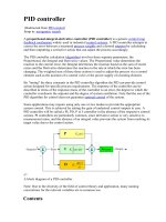
3.6 PID Controller to Control Motor
The strategy of PID control has been one
and send toPC Client
of the
•Torepeat theprogramuntilreceiving thestop
frequently used in industry. This is because that
3.5 Algorithm for PIC Slave 18F4431
the PID controller has a simple form and strong
The flowchart on the circuit PICSlave
18F4431
is
showninFigure8.
PICSlave
18F4431 will performthe workas follows:
sophisticated
methods
and
most
robustness in broad operating area. The
structure of the PID control algorithm is shown
in Fig. 9.
•CreatedtheQEImodule, PWM
•GetconnectedwithI2CMasterPIC18F4450
•Getthevalue ofPWMpulsesfromthe
MasterPIC18F4450
•Send encodervaluestoPICMaster18F4450
•Torepeat theprogramuntilreceiving thestop
signal
Fig 9. The structure of the PID control algorithm
The PID controller output can be expressed
in the time domain as:
u f (t ) K p e(t )
Kp
Ti
t
e(t)dt K T
p d
0
de(t)
(1)
dt
Taking the Laplace transform of (1) yields:
U f (s) K p E(s)
Kp
Ti s
E(s) K pTd sE(s) (2)
The resulting PID controller transfer
function of:
U f ( s)
1
K p 1
Td s
E ( s)
Ti s
(3)
A typical real-time implementation at
sampling sequence k can be expressed as:
Fig 8 . The flowchart on the circuit PIC Slave
18F4431
Trang 30
(4)
TAẽP CH PHAT TRIEN KH&CN, TAP 16, SO K2- 2013
e(k ) y (k ) x(k )
12.From figure 12, it shows that response of
(5)
system is stable. Time delay is happened due to
u f (k ) , e(k ) , y (k ) and x (k )
the system response. Actually, time delay is
are the output of conventional PID controller,
sampling time which is set to control TM via
the error between the desired set point and the
LAN and it is 100 milliseconds. However, this
output, the output and the desired set point,
is acceptable for low cost TM system which is
respectively.
applied to healthcare service.
where
The
effectiveness
algorithm will
be
of
the
proposed
In addition, from Fig. 12, with fast changes
through
of joint angles, and performances with good
demonstrated
experiment.
tracking are also obtainedwith respect to step
inputs. The errors are low and approximate of
120
100
80
60
40
20
0
120
100
80
60
40
20
0
Joint 4
o
Angle [ ]
Joint 2
o
Angle [ ]
120
100
80
60
40
20
0
Joint 3
o
Angle [ ]
Joint 1
o
Angle [ ]
Response
Reference
2% of input amplitude.
In
order
to
improvement
control
performance of system, triangle form and
sinusoidal
form
are
tested,
and
the
experimental result is shown in figure 13 and
figure
14
respectively.From
experimental
results, it is shown that the response of system
with respect to PID controller is stable and
good performance. Time delay is more
happened with respected to sinusoidal form. It
120
100
80
60
40
20
0
is because of the response of control system.
The system is limited with the signal inputs
which have the frequency is greater than 2Hz.
0
10
20
30
40
50
60
Finally, doing practice with movement of
Time [ms]
master manipulator and checking performance
Fig 12. Step response of PID Controller
of salve manipulator. Experimental result is
4. EXPERIMENTAL RESULTS
shown in figure 15. And it is no doubt that the
At first, PID controller is applied for
TM system works well and the proposed
control the motion of slave manipulator. The
algorithms are fine. The responses of slave
control parameters of PID controller are chosen
manipulator are almost tracking with the
through trial and error. And there are
reference input which is given from the motion
K
p
1 . 5 x10
3
,
K i 0 . 15 x10
3
and
of master manipulator.
K d 0 . 2 x10 3 .The experimental result of
The time delay is 100ms with respected to
stepresponse of TMare shown in figure
sampling time to control via LAN and the error
Trang 31
Science & Technology Development, Vol 16, No.K2- 2013
is acceptable which is approximation about 2%
Response
Reference
Joint 4
o
Angle [ ]
120
100
80
60
40
20
0
o
Angle [ ]
80
60
40
20
0
o
Joint 2
Angle [ ]
80
60
40
20
120
100
80
60
40
20
0
0
o
Joint 3
Angle [ ]
80
60
40
20
120
100
80
60
40
20
0
0
o
Joint 4
80
Angle [ ]
Joint 3
o
Angle [ ]
Joint 2
o
Angle [ ]
Joint 1
o
Angle [ ]
Response
Reference
Joint 1
of amplitude of inputs.
60
40
20
0
120
100
80
60
40
20
0
0
10
20
30
40
Time [ms]
Fig 14. Sine response of PID Controller
0
10
20
30
40
50
60
Time [ms]
Response
Reference
Joint 1
o
Angle [ ]
Fig 13. Triangle response of PID Controller
5. CONCLUSIONS
In this paper, a low cost TM system as well
a
good
performance
for
tele-operation
Joint 2
o
Angle [ ]
is shown that the proposed control methods had
120
100
80
60
40
20
0
Joint 3
o
Angle [ ]
as network control algorithms are proposed . It
120
100
80
60
40
20
0
manipulator. It can be seen from experimental
results that the controller had stable and strong
Joint 4
o
Angle [ ]
robustness.
160
140
120
100
80
60
40
20
0
-20
120
100
80
60
40
20
0
0
10
20
30
40
Time [ms]
Fig 15. Real response of TM system
Trang 32
50
60
TẠP CHÍ PHÁT TRIỂN KH&CN, TẬP 16, SỐ K2- 2013
From the experimental results, it shows
This study also show out the flowchart for
PC server, PC Client as well as flowchart of
that
delay
of
response
is
given,
and
low cost circuit using microcontroller PIC
improvement control performance of system
18F4450 and PIC 18F443.
using intelligent control such as neural network
or fuzzy logic will be applied in next study.
ĐIỀU KHIỂN HOẠT ĐỘNG TAY MÁY 4 BẬC TỪ XA
Từ Diệp Cơng Thành
Trường Đại học Bách Khoa, ĐHQG-HCM
TĨM TẮT: Tay máy hoạt động từ xa được biết đến như là giải pháp tốt nhất cho các tương tác
giữa con người với các mơi trường khơng an tồn như nguy hiểm, độc hại, cách ly và vơ trùng. Trong
nghiên cứu này, một hệ thống tay máy điều khiển từ xa giá thành thấp được trình bày. Thêm nữa, giải
thuật điều khiển qua mạng được đề xuất để điều khiển từ xa.
Từ khóa: Hoạt động từ xa, điều khiển, LAN.
Tele- Surgery with Time Delays, First Int.
REFERENCES
Sym. on Medical Robotics and Computer
[1].
N. Tesla., Method of and Apparatus for
Controlling Mechanism of Moving Vessels
or
[2].
[5].
Dong-Soo Kwon, Ki Young Woo, Se
Kyong Song, Wan Soo Kim, Hyung Suck
/>
Cho,
(1898).
Intelligent
Raymond
Goertz,
R.
Thompson,
Controlled
Manipulator,
Nucleonics (1954).
[4].
[6].
Vehicles
Electronically
[3].
Assisted Surgery (1994).
Microsugical
Robots
Telerobot
system,
and
Systems,
Proceedings., 1998 IEEE/RSJ International
Conference, (1998).
[7].
Blake
Hannaford,
Diana
Friedman,
A. K. Bejczy., Sensors, Controls, Man-
Hawkeye King,Mitch Lum, Jacob Rosen,
Machine
Ganesh Sankaranarayanan, Evaluation of
Interface
for
Advanced
Teleoperation, Science (1980).
RAVEN Surgical Telerobot during the
R. D. Ballard., A last long look at Titanic,
NASA Extreme Environment Mission
National Geographic, 170, 6 (1986).
Operations 12 Mission, Report of Dept of
A. Bejczy, G. Bekey, R. Taylor, S.
EE, University of Washington, (2009).
Rovetta, A Research Methodology for
Trang 33
Science & Technology Development, Vol 16, No.K2- 2013
[8].
[9].
Platon A. Prokopiou , Spyros G. Tzafestas,
Internat.
William S. Harwin, A Novel Scheme for
Leuven, Belgium, 1916-1923 (1998).
Human-Friendly and Time-Delays Robust
[11]. Towhidkhah, F., Gander, R. E., Wood, H.
Neuropredictive Teleoperation, Journal of
C., Model predictive control: A model for
Intelligent and Robotic Systems, 25, 4,
joint movement, J. Motor Behavior, 29, 3,
311-340 (1999).
209-222 (1997).
Lee, S., Lee, H. S., Modeling, design and
evaluation
of
advanced
[12]. Prokopiou,
Conf.
P.
on
A.,
Robot.
Automat.,
Harwin,
W.
S.,
teleoperator
Tzafestas, S. G., Variable-time-delays-
control systems with short time delay,
robust telemanipulation through master
IEEE Trans. Robotics Automat, 9, 607-623
state
(1993).
IEEE/ASME Internat, Conf. on Advan.
[10]. Sano, A., Fujimoto, H., Tanaka, M., Gainscheduled compensation for time delay of
bilateral teleoperation, Proc. of IEEE
Trang 34
prediction,
AIM
'99:
1999
Intel. Mechatronics, Atlanta, USA, 19-22
(1999).