Large displacement elastic static analysis of semi rigid planar steel frames by corotational euler–bernoulli finite element
Bạn đang xem bản rút gọn của tài liệu. Xem và tải ngay bản đầy đủ của tài liệu tại đây (2.33 MB, 9 trang )
Journal of Science and Technology in Civil Engineering NUCE 2019. 13 (2): 24–32
LARGE DISPLACEMENT ELASTIC STATIC
ANALYSIS OF SEMI-RIGID PLANAR STEEL FRAMES BY
COROTATIONAL EULER–BERNOULLI FINITE ELEMENT
Nguyen Van Haia , Le Van Binha , Doan Ngoc Tinh Nghiema , Ngo Huu Cuonga,∗
a
Faculty of Civil Engineering, University of Technology, Vietnam National University Ho Chi Minh City,
268 Ly Thuong Kiet street, District 10, Ho Chi Minh City, Vietnam
Article history:
Received 04/03/2019, Revised 22/04/2019, Accepted 22/04/2019
Abstract
A corotational finite element for large-displacement elastic analysis of semi-rigid planar steel frames is proposed in this paper. Two zero-length rotational springs are attached to the ends of the Euler-Bernoulli element
formulated in corotational context to simulate the flexibility of the beam-to-column connections and then the
equilibrium equations of the hybrid element, including the stiffness matrix which contains the stiffness terms
of the rotational springs, are established based on the static condensation procedure. The linear and Kishi-Chen
three-parameter power models are applied in modelling the moment-rotation relation of beam-column connections. The arc-length nonlinear algorithm combined with the sign of displacement internal product are used
to predict the equilibrium paths of the system under static load. The analysis results are compared to previous
studies to verify the accuracy and effectiveness of the proposed element and the applied nonlinear procedure.
Keywords: corotational context; Euler-Bernoulli element; large displacement; semi-rigid connection; steel frame;
static analysis.
/>
c 2019 National University of Civil Engineering
1. Introduction
In structural nonlinear analysis, there are two main finite element formulations depending on
the way of updating the system kinematics during the analysis process such as the Lagrangian and
corotational models. Among these models, the latest developed corotational approach is more simple
and effective than the Lagrangian type in the prediction of the large displacement behaviour of the
structures.
Recent studies based on the corotational formulation for large displacement analysis are briefly
presented as follows. Battini [1] proposed the Bernoulli and Timoshenko beam elements for large
displacement analysis of the 2D and 3D structure under static load with the consideration of material
nonlinearity via von Mises criterion with isotropic hardening at numerical integration points. Yaw
et al. [2] proposed the meshfree formulation for large displacement and material nonlinear analysis
of two-dimensional continua under static load by using maximum-entropy basic functions. Le et al.
[3] derived the elastic force vector and tangent stiffness matrix as well as the inertia terms by using
the cubic interpolation function for lateral displacement for dynamic nonlinear analysis of 2D arches
∗
Corresponding author. E-mail address: (Cuong, N. H.)
24
Hai, N. V., et al. / Journal of Science and Technology in Civil Engineering
and frames. Doan-Ngoc et al. [4] proposed the beam-column elements for second-order plastic-hinge
analysis of planar steel frames by using the approximate seventh-order polynomial function for the
beam-column deflection solutions.
The actual behaviour of the real beam-to-column connections is basically semi-rigid. This connection flexibility affects the response and ultimate strength of the steel frames significantly and
therefore needs be considered in the frame analysis for practical design. So far, many studies have
been done to predict the large displacement response of semi-rigid frames under static and dynamic
loads. However, most of them are related to Lagrangian type formulation, such as the studies of Chan
and Zhou [5], So and Chan [6], Tin-Loi and Misa [7], Park and Lee [8], Ngo-Huu et al. [9], Saritas
and Koseoglu [10], etc. In this study, a corotational finite element is formulated by using the approximate third-order and first-order Hermitian polynomial functions for lateral deflection and axial
deformation, respectively, for large displacement analysis of planar steel frames under static load. An
effective strain is applied to avoid membrane locking as discussed by Crisfield [11]. The semi-rigid
connection is modelled as rotational springs attached at the ends of corotational element to simulate
the moment-rotation relation. Then, the static condensation algorithm is applied to eliminate the internal degrees of freedom between element ends and rotational springs at the same positions. As the
result, a new element stiffness matrix considering the connection flexibility is formulated with the
same size as normal finite element. The linear rotational spring or the Kishi-Chen three-parameter
power model (Lui and Chen [12]) is used to describe the beam-to-column flexibility. The arc-length
nonlinear algorithm is combined with the sign of displacement internal product proposed by Posada
[13] in order to solve the nonlinear equilibrium systems. The analysis results are compared to the
previous studies to verify
accuracy
and effectiveness
of theNUCE
proposed
Journalthe
of Science
and Technology
in Civil Engineering
2019. 13element.
(x): x–xx
2. Finite element
formulation
2. Finite
element formulation
2.1 Corotational finite element
2.1. Corotational
finite element
The original undeformed and current deformed configurations of the element in the
The original
undeformed and current deformed configurations of the element in the global coorglobal coordinate system (X, Y) are shown in Figure 1. A local coordinate system (XL,
dinate system Y
(X,
Y) are shown in Fig. 1. A local coordinate system (XL , YL ) is attached to the element
L) is attached to the element at the left node and it continuously moves with the
at the left nodeelement.
and it continuously moves with the element.
Figure
Kinematicmodel
model of
of corotational
Figure
1.1.Kinematic
corotationalelement
element
The global displacement vector is defined by
d = [u1
w1
q1 u2
w2
q2 ]
T
(1)
The local displacement vector is defined by
25
d L = [u L
qL1
qL2 ]
T
(2)
The vectors of global and local internal force are respectively given by
T
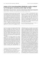
Hai, N. V., et al. / Journal of Science and Technology in Civil Engineering
The global displacement vector is defined by
d=
u1 w1 q1 u2 w2 q2
T
(1)
The local displacement vector is defined by
dL =
uL qL1 qL2
T
(2)
The vectors of global and local internal force are respectively given by
f =
fL =
N1 Q 1
NL
M1 N2 Q2
ML1
ML2
M2
T
T
(3)
(4)
The components of dL are computed by
u L = l − l0 ,
θL1 = θ1 − θr ,
θL2 = θ2 − θr
(5)
where l0 and l are original and current length of the element respectively and θr is the rigid rotation.
By equating the virtual work in both local and global coordinate system, the relation between the local
internal force vector fL and global one f is obtained as follows
f = BT fL
(6)
∂dL
where B =
is the corotational transformation matrix.
∂d
The global tangent stiffness matrix is obtained through differentiation of the internal force vector
f , δ f = Kδd in combination with Eq. (6) [2], as follows
K = BT KL B + A1 NL + A2 (ML1 + ML2 )
(7)
where
∂ fL
(8)
∂dL
∂2 uL
(9)
A1 =
∂d2
∂2 θr
A2 =
(10)
∂d2
According to Crisfield [11], an effective strain εe f is applied to avoid membrane locking. In EulerBernoulli assumption, the strain ε is defined as
∂u 1 ∂w 2
1
ε = εe f − yκ =
(11)
+
dξ − yκ
2
∂ξ 2 ∂ξ
KL =
L
where u and w are the axial and lateral displacements using a linear interpolation function and cubic
one, respectively.
The principle of virtual work is used to calculate the local internal forces as follows
V=
σδεdV = NL δuL + ML1 δθL1 + ML2 δθL2
(12)
V
The components of fL are calculated from Eq. (12). Then, the local tangent stiffness matrix is determinated from Eq. (8) and the global one is easily determined from Eq. (7). For elastic analysis, the
Gauss quadrature with two Gauss points is exact enough to calculate the numerical values of fL , KL
and K.
26
Hai, N. V., et al. / Journal of Science and Technology in Civil Engineering
2.2. Hybrid corotational element
The initial corotational finite element has to satisfy the equilibrium equation K d = P . Be6×6 6×1
6×1
cause K is the global tangent stiffness matrix, both of d and P must be formed in global coordinate
system. The nodal load vector in the global coordinate system is
P = TP
(13)
where T is the transformation matrix and P is nodal load vector in the local coordinate system
P =
P1 V1
M1 P2 V2
M2
T
(14)
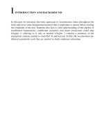
In semi-rigid beam-to-column connection, only rotational deformation is considered due to negligible axial and shear strains. An assembly procedure is described in Fig. 2. The semi-rigid connections
are modelled as a zero-length rotational springs attached to nodes A and B of the element. The equilibrium equation at element level K ∗ d∗ = f ∗ has 8 degrees of freedom. Then, a static condensation
8×8 8×1
8×1
algorithm proposed by Wilson [14] is used to eliminate the first and second degrees of freedom. As
a result, a 6-DOFs hybrid
element is formulated as normal finite element. The hybrid element sigJournal of Science and Technology in Civil Engineering NUCE 2019. 13 (x): x–xx
nificantly reduces the computational cost because the rotational displacements at nodes A and B are
not included in the global stiffness matrix. However, an updated displacement procedure at nodes A
coordinate system
and B must be required at each nonlinear solution iteration to find the rigid rotations of semi-rigid
T
(14)
connection.
P¢ = {P1' V1' M 1' P2' V2' M 2' }
Figure 2. Formulation of hybrid corotational element
Figure
2. Formulation of hybrid corotational element
2.3.
In semi-rigid beam-to-column connection, only rotational deformation is considered
due to negligible axial and shear strains. An assembly procedure is described in Figure
The semi-rigid connections are modelled as a zero-length rotational springs attached
Algorithm2.of
nonlinear equation solution
to nodes A and B of the element. The equilibrium equation at element level
At each iteration
out ofofbalance
defined
as
K * d * = loop,
f * has the
8 degrees
freedom. vector
Then, a is
static
condensation
algorithm proposed
8´8 8´1
8´1
i−1 andi−1
by Wilson [14] is used to eliminate
the first
second degrees of freedom. As a
Ri−1
(15)
j = F in j − λ j F ex
result, a 6-DOFs hybrid element is formulated as normal finite element. The hybrid
element significantly reduces the computational cost because the rotational
where Fin is the
internal force vector which is assembled from vector f , Fex is the reference load vector
displacements at nodes A and B are not included in the global stiffness matrix.
and λ is the load factor. In order to find the equilibrium path of system at snapback and snapthrough
However, an updated displacement procedure at nodes A and B must be required at
point, the spherical
arc-length nonlinear algorithm is used in combination with the scalar product
each nonlinear solution iteration to find the rigid rotations of semi-rigid connection.
2.3 Algorithm of nonlinear equation solution
27
At each iteration loop, the out of balance vector is defined as
R ij-1 = Fin ij-1 - l ij-1Fex
(15)
where Fin is the internal force vector which is assembled from vector f , Fex is the
Hai, N. V., et al. / Journal of Science and Technology in Civil Engineering
criterion proposed by Posada [13]. The sign of incremental load factor ∆λ1j at the first iteration of
each incremental load level is
∆s j
∆λ1j = ±
(16)
T
1
1
δˆu j
δˆu j
sign ∆λ1j = sign {∆u}satisfied
j−1
T
{δˆu}1j
(17)
where ∆λ1j and {∆u}satisfied
are the incremental load factor at jth loadstep and the previous converged
j−1
andis
Technology
in Civil Engineering
NUCEdisplacement
2019. 13 (x): x–xx vector.
incremental displacement vector, Journal
δˆu1j =of Science
K 0j Fex
the current
tangential
3. Numerical examples
[13]. The sign of incremental load factor Dl1j at the first iteration of each incremental
load level is
Ds j
A structural analysis program
in
MATLAB programming language is developed
Dl1written
(16) to predict
j = ±
1 T
.( duˆ 1j )semi-rigid planar members and frames under static
( duˆ j ) and
the large displacement responses of rigid
T
load based on the above-mentioned algorithm.
Itssatisfied
accuracy
is verified through following numerical
1
(17)
sign( Dl1j ) = sign æç ({Du} j -1 ) {duˆ } j ö÷
è
ø
examples.
where Dl1j and
{Du} j -1
satisfied
are the incremental load factor at jth loadstep and the
3.1. Pinned-fixed square diamond
frame
previous converged
incremental displacement vector, duˆ 1j = K 0j Fex is the current
tangential displacement vector.
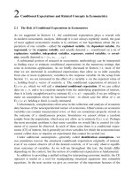
The geometric and material properties of the diamond frame and its equivalent system are shown
3. Numerical examples
in The geometric and material properties of the diamond frame and its equivalent system are shown in
A structural analysis program written in MATLAB programming language is
Fig. 3. The variations of thedeveloped
analysisto results
with
number
elements
predict the
largedifferent
displacement
responsesof
of proposed
rigid and semi-rigid
planarin modeling
members
and
frames
under
static
load
based
on
the
above-mentioned
algorithm.
Its proposed
each member shown in Fig. 4 indicate that the analysis result is converged by the use of three
accuracy is verified through following numerical examples.
elements per member. It can be seen that the results using three proposed elements per member are
3.1 Pinned-fixed square diamond frame
almost identical to Mattiasson’s
elliptic integral solution [15] in two cases of tensile and compressive
The geometric and material properties of the diamond frame and its equivalent system
loads as shown in Fig. 5. are shown in
Journal of Science and Technology in Civil Engineering NUCE 2019. 13 (x): x–xx
Figure 3. Diamond frame
Journal of Science and Technology in Civil Engineering NUCE 2019. 13 (x): x–xx
Figure 3.ofDiamond
Figure 3. The variations
the analysisframe
results with different number of proposed
elements in modeling each member shown in Figure 4 indicate that the analysis result
is converged by the use of three proposed elements per member. It can be seen that the
results using three proposed elements per member are almost identical to Mattiasson’s
elliptic integral solution [15] in two cases of tensile and compressive loads as shown in
Figure 5.
6
Figure 5. Load-deflection curves of diamond frame
Figure 4. Analysis results using different number of proposed element per member
Figure
4. Analysis results using different number of
proposed element per member
Figure 5. Load-deflection curves of diamond frame
3.2 Lee’s frame
28
Hai, N. V., et al. / Journal of Science
The geometric and material properties of Lee’s frame are shown in Figure 6. Park and
Lee [8] used ten linearized finite elements while Le et al. [2] used twenty Timoshenko
corotational elements in analysis. The equilibrium path of the frame with three
proposed elements per member (Figure 7) converges in good agreement with the
results obtained by Park and Lee[8] and Battini [1] as shown in Figure 8. The analysis
results also show that the developed program can handle the critical points as snapback and snap-through and draw entire load-displacement curve with the least number
and
Technology in Civil Engineering
of elements in comparison to the above-mentioned authors.
Journal of Science and Technology in Civil Engineering NUCE 2019. 13 (x): x–xx
3.2. Lee’s frame
The geometric and material properties of Lee’s frame are shown in Fig. 6. Park and Lee [8]
The geometric and material properties of Lee’s frame are shown in Figure 6. Park and
used ten linearized finite elements while Le et al. [2] used twenty Timoshenko corotational elements
Lee [8] used ten linearized finite elements while Le et al. [2] used twenty Timoshenko
in elements
analysis.
equilibrium
pathpathofofthe
withthree
three proposed elements per member (Fig. 7)
corotational
in The
analysis.
The equilibrium
the frame
frame with
proposed converges
elements per in
member
7) converges
good
agreement
with theby Park and Lee [8] and Battini [1] as shown
good(Figure
agreement
withinthe
results
obtained
results obtained
by Park
and Lee[8]
and Battini
[1] asalso
shown
in Figure
in Fig.
8. The
analysis
results
show
that8. The
the analysis
developed program can handle the critical points
results also show that the developed program can handle the critical points as snapas snap-back and snap-through and draw entire load-displacement curve with the least number of
back and snap-through and draw entire load-displacement curve with the least number
Figure 6. Lee's frame
elements
in comparison
to theauthors.
above-mentioned authors.
of elements
in comparison
to the above-mentioned
Figure 7. Load-displacement curves with different number of elements
Figure 6. Lee's frame
Figure 6. Lee’s frame
Figure
7.2019.
Load-displacement
curves with different
Journal of Science and Technology in Civil Engineering
NUCE
13 (x): x–xx
number of9 elements
Figure 8. Displacement at point load
Figure
at point load
Figure 7. Load-displacement curves with
different
number8.ofDisplacement
elements
3.3 Eccentrically loaded column with linear semi-rigid connection
9
3.3. Eccentrically loaded
column with linear semi-rigid connection
An eccentrically loaded column with geometric and material properties shown in Fig. 9 was analysed by So and Chan [6] using 3-node element which is established by fourth-order polynomial function for lateral displacement v and the minimum residual displacement algorithm. The convergence
of the equilibrium path according to number of proposed elements is shown in Fig. 10. It can be seen
that the column must be modelled at least three proposed elements in two cases in order to have the
results identical to those of So and Chan [6] using two fourth-order elements as shown in Fig. 11.
3.4. Cantilever beam with a semi-rigid connection
A cantilever beam subjected to a point load at free end shown in Fig. 12(b) was studied by
Aristizábal-Ochoa [16] using the classical algorithm of Elastica and the corresponding elliptical functions. Kishi-Chen three-parameter power model is10applied in modelling semi-rigid behaviour of end
29
Figure 9 was analysed by So and Chan [6] using 3-node element which is established
by fourth-order polynomial function for lateral displacement v and the minimum
residual displacement algorithm. The convergence of the equilibrium path according to
number of proposed elements is shown in Figure 10. It can be seen that the column
must be modelled at least three proposed elements in two cases in order to have the
Figure 6. Lee's frame
results identical to those of So and Chan
as shown
Hai,[6]
N.using
V., ettwo
al. fourth-order
/ Journal of elements
Science and
Technology in Civil Engineering
in Figure 11.
Figure
Load-displacement
curves with different number of elements
Journal of Science and Technology in Civil Engineering
NUCE7.2019.
13 (x): x–xx
Figure 9. Eccentrically loaded column
Figure
9. Eccentrically loaded column
Figure 10. Convergence of the equilibrium path
according to number 9of proposed elements
Journal of Science and Technology in Civil Engineering NUCE 2019. 13 (x): x–xx
Journal of Science and Technology in Civil Engineering NUCE 2019. 13 (x): x–xx
A cantilever beam subjected to a point load at free end shown in
A connection
cantilever beam
to astructural
point load
at free end shown in
rigid
modelsubjected (b)
model
(a) semi-
(a) semirigid
connection
model
(b)
structural
model
Figure 12 (b) was studied by Aristizábal-Ochoa [16] using the classical algorithm of
Figure 11. Displacements at free end
Elastica
elliptical
functions. Kishi-Chen
three-parameter
Figureand
12the
(b)corresponding
was studied
Aristizábal-Ochoa
the classical power
algorithm of
Figureby
11.
Displacements
at[16]
freeusing
end
model
is applied
modelling
semi-rigid
behaviour
of
end
connection
shown
in power
Elastica
and3.4theinCantilever
corresponding
elliptical
functions.
Kishi-Chen
three-parameter
beamto
with
a semi-rigid
connection
Figure 10. Convergence of the equilibrium path according
number
of proposed
(a)model
semi-rigid
connection
model
(b) structural
model of end connection shown in
is
applied
in
modelling
semi-rigid
behaviour
connection shown
in elements
Fig. 12(a). The analysis
with
eight model
proposed elements per member show
(a) semi-rigid
modelwithresults
structural
Figure
12(a). Theconnection
analysis results
eight (b)
proposed
elements per member show
good convergence
with Aristizábal-Ochoa’s solution as shown in Fig. 13.
good convergence with Aristizábal-Ochoa’s solution as shown in Figure 13.
Figure 12(a).
11 The analysis results with eight proposed elements per member show
good convergence with Aristizábal-Ochoa’s solution as shown in Figure 13.
12
semi-rigidconnection
connectionmodel
model
(a)(a)
Semi-rigid
(b) structural
model model
(b) Structural
Figure 12. Cantilever beam with semi-rigid connection
(a)
semi-rigid
connectionbeam
model
(b) structural
model
Figure
12. Cantilever
with semi-rigid
connection
Figure 12. Cantilever beam with semi-rigid connection
3.5. Williams’ toggle frame
The Williams’ toggle frame shown in Fig. 14 was analysed with three cases of different support
conditions: (1) rigid connection; (2) linear semi-rigid connection; (3) hinge connection. In the first
case, the analysis results of the proposed program well converge to Williams’ analytical solution [17]
30
Journal of Science and Technology in Civil Engineering NUCE 2019. 13 (x): x–xx
Hai, N. V., et al. / Journal of Science and Technology in Civil Engineering
Figure 13. Displacements at free end
3.5 Williams’ toggle frame
The Williams’ toggle frame shown in Figure 14 was analysed with three cases of
different support conditions: (1) rigid connection; (2) linear semi-rigid connection; (3)
13.the
Displacements
at free end
hinge connection. In the firstFigure
case,
analysis results
of the proposed program well
Figure
13.
Displacements
at free end
toggle
frame
converge3.5toWilliams’
Williams’
analytical
solution [17] until the deflection ratio (d/h) of about
The Williams’
frame elements
shown in Figure
14 was analysed
with
1.2 by using
only twotoggle
proposed
per member
as shown
inthree cases of
until the deflection ratio
(δ/h)
of about
1.2(1)by
using
only(2)two
proposed
elements
different
support
conditions:
rigid
connection;
linear
semi-rigid connection;
(3) per member as shown
15.
For
all threeIn cases,
with
two proposed
elements
per
hinge
connection.
the first the
case, analysis
the analysisresults
of
the proposed
program
well
Journal proposed
of Science and Technology
in Civil Engineering
NUCE 2019. 13 (x):
x–xx
in Fig. 15. For Figure
all three
cases,
the analysis
results
withresults
two
elements
per member
coincide
Williams’
solution by
[17]Tin-Loi
until the deflection
of about in Figure
member converge
coincideto with
the analytical
ones obtained
and Misaratio
[7](d/h)
as shown
with the ones obtained1.2byby Tin-Loi
and
Misaelements
[7] aspershown
inshown
Fig.in16.
using only two
proposed
member as
16.
Figure 15. For all three cases, the analysis results with two proposed elements per
member coincide with the ones obtained by Tin-Loi and Misa [7] as shown in Figure
16.
Figure14.
14.Williams’
Williams’ toggle
toggle frame
Figure
frame
Williams’ toggleFigure
frame
15. Load-deflection curves according to number of elements
Journal of Science and Technology in Civil Engineering NUCE 2019. 13 Figure
(x): x–xx 14.
14
14
Figure 16. P-d relation curves
Figure 15. Load-deflection curves according to number of elements
Figure 15. Load-deflection curves according to
number of elements
Figure 16. P-δ relation curves
15
4. Conclusions
A hybrid corotational finite element for large-displacement elastic analysis of semi-rigid planar
steel frames is presented in this study. The semi-rigid connections are modelled by zero-length rotational springs with linear or nonlinear behaviour of moment-rotation relation. A Matlab computer
31
Figure 16. P-d relation curves
15
Hai, N. V., et al. / Journal of Science and Technology in Civil Engineering
program using arc-length method combined the sign of displacement internal product is developed to
solve nonlinear equilibrium equation system. The results of numerical examples prove that the proposed hybrid element can accurately predict the large displacement behaviour of semi-rigid planar
steel frames subjected to static load.
Acknowledgements
This research is funded by Vietnam National Foundation for Science and Technology Development (NAFOSTED) under grant number 107.01-2016.34.
References
[1] Battini, J.-M. (2002). Co-rotational beam elements in instability problems. PhD thesis, KTH, Stockholm,
Sweden.
[2] Yaw, L. L., Sukumar, N., Kunnath, S. K. (2009). Meshfree co-rotational formulation for two-dimensional
continua. International Journal for Numerical Methods in Engineering, 79(8):979–1003.
[3] Le, T.-N., Battini, J.-M., Hjiaj, M. (2011). Efficient formulation for dynamics of corotational 2D beams.
Computational Mechanics, 48(2):153–161.
[4] Doan-Ngoc, T.-N., Dang, X.-L., Chu, Q.-T., Balling, R. J., Ngo-Huu, C. (2016). Second-order plastichinge analysis of planar steel frames using corotational beam-column element. Journal of Constructional
Steel Research, 121:413–426.
[5] Chan, S. L., Zhou, Z. H. (1994). Pointwise equilibrating polynomial element for nonlinear analysis of
frames. Journal of structural engineering, 120(6):1703–1717.
[6] So, A. K. W., Chan, S. L. (1995). Buckling and geometrically nonlinear-analysis of frames using one
element member-reply. Journal of Constructional Steel Research, 32(2):227–230.
[7] Tin-Loi, F., Misa, J. S. (1996). Large displacement elastoplastic analysis of semirigid steel frames. International Journal for Numerical Methods in Engineering, 39(5):741–762.
[8] Park, M. S., Lee, B. C. (1996). Geometrically non-linear and elastoplastic three-dimensional shear flexible
beam element of von-Mises-type hardening material. International Journal for Numerical Methods in
Engineering, 39(3):383–408.
[9] Ngo-Huu, C., Nguyen, P.-C., Kim, S.-E. (2012). Second-order plastic-hinge analysis of space semi-rigid
steel frames. Thin-Walled Structures, 60:98–104.
[10] Saritas, A., Koseoglu, A. (2015). Distributed inelasticity planar frame element with localized semi-rigid
connections for nonlinear analysis of steel structures. International Journal of Mechanical Sciences, 96:
216–231.
[11] De Borst, R., Crisfield, M. A., Remmers, J. J. C., Verhoosel, C. V. (2012). Nonlinear finite element
analysis of solids and structures. John Wiley & Sons.
[12] Lui, E. M., Chen, W.-F. (1986). Analysis and behaviour of flexibly-jointed frames. Engineering Structures, 8(2):107–118.
[13] Posada, L. M. (2007). Stability analysis of two-dimensional truss structures. Master’s thesis, University
of Stuttgart, Germany.
[14] Wilson, E. L. (1974). The static condensation algorithm. International Journal for Numerical Methods
in Engineering, 8(1):198–203.
[15] Mattiasson, K. (1981). Numerical results from large deflection beam and frame problems analysed by
means of elliptic integrals. International Journal for Numerical Methods in Engineering, 17(1):145–153.
[16] Aristizábal-Ochoa, J. D. ı. o. (2004). Large deflection stability of slender beam-columns with semirigid
connections: Elastica approach. Journal of Engineering Mechanics, 130(3):274–282.
[17] Williams, F. W. (1964). An approach to the non-linear behaviour of the members of a rigid jointed plane
framework with finite deflections. The Quarterly Journal of Mechanics and Applied Mathematics, 17(4):
451–469.
32