Ritz solution for buckling analysis of thin walled composite channel beams based on a classical beam theory
Bạn đang xem bản rút gọn của tài liệu. Xem và tải ngay bản đầy đủ của tài liệu tại đây (2.87 MB, 11 trang )
Journal of Science and Technology in Civil Engineering NUCE 2019. 13 (3): 34–44
RITZ SOLUTION FOR BUCKLING ANALYSIS OF THIN-WALLED
COMPOSITE CHANNEL BEAMS BASED ON A CLASSICAL
BEAM THEORY
Nguyen Ngoc Duonga,∗, Nguyen Trung Kiena , Nguyen Thien Nhanb
a
Faculty of Civil Engineering, HCMC University of Technology and Education,
No 1 Vo Van Ngan street, Thu Duc district, Ho Chi Minh city, Vietnam
b
Faculty of Engineering and Technology, Kien Giang University,
320A Route 61, Chau Thanh district, Kien Giang province, Vietnam
Article history:
Received 05/08/2019, Revised 28/08/2019, Accepted 30/08/2019
Abstract
Buckling analysis of thin-walled composite channel beams is presented in this paper. The displacement field
is based on classical beam theory. Both plane stress and plane strain state are used to achieve constitutive
equations. The governing equations are derived from Lagrange’s equations. Ritz method is applied to obtain
the critical buckling loads of thin-walled beams. Numerical results are compared to those in available literature
and investigate the effects of fiber angle, length-to-height’s ratio, boundary condition on the critical buckling
loads of thin-walled channel beams.
Keywords: Ritz method; thin-walled composite beams; buckling.
/>
c 2019 National University of Civil Engineering
1. Introduction
Composite materials are widely used in many fields of civil, aeronautical and mechanical engineering owing to low thermal expansion, enhanced fatigue life, good corrosive resistance, and high
stiffness-to-weight and strength-to-weight ratios. A large number of structural members made of composites have the form of thin-walled beams. In addition to the increasing in application, thin-walled
composite beams also attract a huge attention from reseachers to study their structural behaviours.
The thin-walled theories are presented by [1, 2]. Bauld and Lih-Shyng [3] then developed Vlasov’s
thin-walled isotropic material beam theory for the composite one. Gupta et al. [4] used finite element
method (FEM) for analysing thin-walled Z-section laminated anisotropic beams. Bank and Bednarczyk [5] proposed a thin-walled beam theory for bending analysis of composite beams by considering
shear deformation. In this study, the Timoshenko beam theory together with a modified form of the
shear coefficient are developed. An analytical study for flexural-torsional stability of thin-walled composite I-beams is presented by [6, 7]. Based on FEM and classical lamination theory, [8–10] predicted
flexural-torsional buckling load of thin-walled composite beams. Navier solution is used by [11] for
buckling and free vibration analysis of thin-walled composite beams. Shan and Qiao [12] conducted
a combined analytical and experimental study for buckling behaviours of composite channel beams
by considering the bending-twisting coupling and shear effect. Cortinez and Piovan [13] used FEM
∗
Corresponding author. E-mail address: (Duong, N. N.)
34
this paper is to apply a Ritz solution for the buckling analysis of thin-walle
beams. The governing equations are derived by using Lagrange’s equation
the present element are compared with those in available literature to show
Duong, N. N., et al. / Journal of Science and Technology in Civil Engineering
of the present solution. Parametric study is also performed to investigate t
for the stability analysis length-to-height
of thin-walled composite
displacement
fields buckling
in this studyloads
are of the
ratio,beams.
fibreThe
angle
on critical
developed by using non-linear theory. The exact stiffness matrix method are proposed by [14, 15] for
composite beams.
flexural-torsional stability analysis of thin-walled composite I-beams. Vo and Lee [16, 17] used FEM
for flexural-torsional stability
analysis of thin-walled
composite beams. In recent years, buckling be2. Theoretical
formulation
haviours of thin-walled functionally grade open section beams are also analysed [18–21]. It can be
seen that Ritz method has seldom
used to analyse
the buckling
problemthree
of thin-walled
composite systems
Thebeen
theoretical
development
requires
sets of coordinate
channel beams.
Fig.1. The first coordinate system is the orthogonal Cartesian coordinate
In this paper, the bending and warping shears are considered. The main novelty of this paper is
theanalysis
y- andofz-axes
lie in composite
the plane beams.
of the cross-section
to apply a Ritz solution z),
for for
the which
buckling
thin-walled
The governing and the x
the Lagrange’s
longitudinal
axis ofResults
the beam.
second
coordinate
system is th
equations are derived byto
using
equations.
of the The
present
element
are compared
with those in available literature
to
show
its
accuracy
of
the
present
solution.
Parametric
study
is
also
coordinate (n, s, x) wherein the n axis is normal to the middle surface of a p
performed to investigate the effects of length-to-height ratio, fibre angle on critical buckling loads of
the s axis is tangent to the middle surface and is directed along the contou
the thin-walled composite beams.
cross-section. q s is an angle of orientation between (n, s, x) and (x, y, z
2. Theoretical formulation
systems. The pole P , which has coordinate ( yP , zP ), is called the shear cen
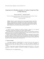
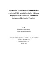
The theoretical development requires three
sets of coordinate systems as shown in Fig. 1. The
first coordinate system is the orthogonal Cartesian
coordinate system (x, y, z), for which the y- and zaxes lie in the plane of the cross-section and the x
axis parallel to the longitudinal axis of the beam.
The second coordinate system is the local plate coordinate (n, s, x) wherein the n axis is normal to
the middle surface of a plate element, the s axis is
tangent to the middle surface and is directed along
the contour line of the cross-section. θ s is an angle
of orientation between (n, s, x) and (x, y, z) coordinate systems. The pole P, which has coordinate
(yP , zP ), is called the shear center [22].
z
s,w
n,v
z
x,u
r
W
q
f
zp
s
qs
V
P
x
yp
y
y
x
Figure
1. Thin-walled
systems
Figure
1. Thin-walled coordinate
coordinate systems
2.1. Constitutive relations
2.1. Constitutive relations
th
The constitutive equationsThe
for the
kth -ply in the
global coordinate
(n,in
s, x)
areglobal
given by:
k -ply
constitutive
equations
for the system
the
coordinate sys
aregiven(k)
by: ¯
σ
Q11 Q¯ 12 Q¯ 16
x
σs
σ
xs
= Q¯ 12 Q¯ 22 Q¯ 26
¯
Q16 Q¯ 26 Q¯ 66
(k)
εx
εs
γ
xs
(1)
where Q¯ i j are transformed reduced stiffnesses. The one-dimensional stress states of thin-walled composite beams are derived from Eq. (1) by assuming plane strain or plane stress state [23, 24]:
σx
σ xs
(k)
=
Q¯ 11 Q¯ 16
Q¯ 16 Q¯ 66
(k)
εx
γ xs
2
(2)
- For plane strain state (ε s = 0):
Q¯ 11 = Q¯ 11 , Q¯ 16 = Q¯ 16 , Q¯ 66 = Q¯ 66
35
(3)
Duong, N. N., et al. / Journal of Science and Technology in Civil Engineering
- For plane stress state (σ s = 0):
Q¯ 226
Q¯ 212 ¯
Q¯ 12 Q¯ 26 ¯
¯
¯
¯
¯
, Q16 = Q16 −
, Q66 = Q66 −
Q11 = Q11 −
Q¯ 22
Q¯ 22
Q¯ 22
(4)
Constitutive equation in Eq. (2) can be also applied for thin-walled isotropic beams [25]:
Q¯ 11 = E, Q¯ 16 = 0, Q¯ 66 = G =
E
2 (1 + υ)
(5)
where E, G and υ are Young’s modulus, shear modulus and Poisson ratio of isotropic material, respectively.
2.2. Kinematics
The mid-surface displacements (¯u, v¯ , w)
¯ at a point in the contour coordinate system are written by
[26, 27]:
v¯ (s, x) = V (x) sin θ s (s) − W (x) cos θ s (s) − φ (x) q (s)
(6)
w¯ (s, x) = V (x) cos θ s (s) + W (x) sin θ s (s) + φ (x) r (s)
u¯ (s, x) = U (x) − V,x (x) y (s) − W,x (x) z (s) − ψ (x)
(s)
(7)
(8)
where the comma symbol indicates a partial differentiation with respect to the corresponding subscript coordinate. U, V and W are displacement of P in the x-, y- and z- directions, respectively; φ is
the rotation angle about pole axis; is warping function given by:
s
(s) =
r (s)ds
(9)
s0
It can be seen that displacement fields in Eqs. (6)–(8) are derived from Vlasov assumption which
∂w¯ ∂¯u
shear strain of the mid-surface is zero in each plate γ¯ sx =
+
= 0 [1, 27]. The displacements
∂x ∂s
(u, v, w) at any generic point on section are obtained from Kirchhoff–Love’s the classical plate theory
which ignored shear deformation [27]:
v (n, s, x) = v¯ (s, x)
(10)
w (n, s, x) = w¯ (s, x) − n¯v,s (s, x)
(11)
u (n, s, x) = u¯ (s, x) − n¯v,x (s, x)
(12)
ε x = ε¯ x + n¯κ x
(13)
γ sx = n¯κ sx
(14)
The strains fields are obtained:
where
ε¯ x =
∂2 v¯
∂2 v¯
∂¯u
, κ¯ x = − 2 , κ¯ sx = −2
∂x
∂s∂x
∂x
36
(15)
Duong, N. N., et al. / Journal of Science and Technology in Civil Engineering
In Eq. (15), ε¯ x , κ¯ x and κ¯ sx are mid-surface axial strain and biaxial curvature of the plate, respectively. Thin-walled beam strain fields can be obtained by substituting Eqs. (6)–(8) into Eq. (15) as:
ε¯ x = ε0x + yκz + zκy +
κ
(16)
κ¯ x = κz sin θ − κy cos θ − κ q
(17)
κ¯ sx = κ sx
(18)
ε0x , κy , κz , κ
where
, κ sx are axial strain, biaxial curvatures in the y and z direction, warping curvature
with respect to the shear center, and twisting curvature in the beam, respectively defined as:
ε0x = U,x
(19)
κy = −W,xx
(20)
κz = −V,xx
(21)
κ = −φ,xx
(22)
κ sx = −2φ,x
(23)
Substituting Eqs. (16)–(23) into Eqs. (13)–(14), the strains fields of thin-walled beam can be written as:
(24)
ε x = ε0x + (y + n sin θ) κz + (z − n cos θ) κy + ( − nq) κ
γ sx = nκ sx
(25)
2.3. Variational formulation
The strain energy ΠE of the beam is given by:
ΠE =
=
1
2
(σ x ε x + σ sx γ sx )dΩ
Ω
L
1
2
2
2
− 2E12 U,x V,xx − 2E13 U,x W,xx − 4E14 U,x φ,x + E22 V,xx
+ 2E24 V,xx φ,xx
E11 U,x
(26)
0
2
+E33 W,xx
+ 2E34 W,xx φ,xx − 4E35 W,xx φ,x + E44 φ2,xx + 4E55 φ2,x dx
where Ω is volume of beam, Ei j is stiffness of thin-walled composite beam (see [9] for more detail).
The potential energy ΠW of thin-walled beam subjected to axial compressive load N0 can be
expressed as:
N0 2
1
v + w2,x dΩ
ΠW = −
2
A ,x
Ω
L
1
=−
2
(27)
IP
N0 V,x2 + W,x2 + 2z p V,x φ,x − 2y p W,x φ,x + φ2,x dx
A
0
where A is the cross-sectional area, IP is polar moment of inertia of the cross-section about the centroid defined by [8, 18]:
I P = Iy + Iz
(28)
37
Duong, N. N., et al. / Journal of Science and Technology in Civil Engineering
where Iy and Iz are second moment of inertia with respect to y- and z-axis, respectively, given by:
Iy =
z2 dA
(29)
y2 dA
(30)
A
Iz =
A
The total potential energy of thin-walled beam is expressed by:
Π = Π E + ΠW
L
1
=
2
2
2
E11 U,x
− 2E12 U,x V,xx − 2E13 U,x W,xx − 4E14 U,x φ,x + E22 V,xx
+ 2E24 V,xx φ,xx
0
2
+E33 W,xx
+ 2E34 W,xx φ,xx − 4E35 W,xx φ,x + E44 φ2,xx + 4E55 φ2,x dx
(31)
L
1
−
2
N0 V,x2 + W,x2 + 2z p V,x φ,x − 2y p W,x φ,x +
IP 2
φ dx
A ,x
0
2.4. Ritz solution
By using the Ritz method, the displacement field is approximated by:
m
U(x) =
ϕ j,x (x)U j
(32)
ϕ j (x)V j
(33)
ϕ j (x)W j
(34)
ϕ j (x)φ j
(35)
j=1
m
V(x) =
j=1
m
W(x) =
j=1
m
φ(x) =
j=1
where U j , V j , W j and φ j are unknown and need to be determined; ϕ j (x) are approximation functions
[21]. It should be noted that these approximation functions in Table 1 satisfy the various boundary
conditions (BCs) such as simply-supported (S-S), clamped-free (C-F), clamped-simply supported (CS) and clamped-clamped (C-C).
By substituting Eqs. (32)–(35) into Eq. (31) and using Lagrange’s equations:
∂Π
=0
∂p j
(36)
with p j representing the values of U j , V j , W j , φ j , the buckling behaviours of the thin-walled beam
can be obtained by solving the following equations:
K11 K12 K13 K14
u
0
T 12
22
23
24
v
0
K
K
K
K
=
(37)
T K13 T K23 K33 K34
w
0
T 14 T 24 T 34
K
K
K
K44 Φ 0
38
Duong, N. N., et al. / Journal of Science and Technology in Civil Engineering
Table 1. Approximation functions and essential BCs of thin-walled beams
ϕ j (x)
BC
e
− jx
L
x
x
1−
L
L
x 2
L
x 2
x
1−
L
L
x 2
x 2
1−
L
L
S-S
C-F
C-S
C-C
x=0
x=L
V=W=φ=0
V=W=φ=0
U=V=W=φ=0
V,x = W,x = φ,x = 0
U = V = W = φ = 0,
V,x = W,x = φ,x = 0
U = V = W = φ = 0,
V,x = W,x = φ,x = 0
V=W=φ=0
U = V = W = φ = 0,
V,x = W,x = φ,x = 0
where the stiffness matrix K is given by:
L
L
Ki11j = E11
ϕi,xx ϕ j,xx dx, Ki12j = −E12
0
= 2E15
ϕi,xx ϕ j,x dx − E14
= E23
L
ϕi,xx ϕ j,xx dx,
= E22
Ki24j
0
= E24
0
= E33
= E34
0
L
0
0
ϕi,xx ϕ j,xx dx − 2E35
L
ϕi,xx ϕ j,x dx − N0 y p
0
L
ϕi,xx ϕ j,xx dx − 2E45
0
ϕi,x ϕ j,x dx,
L
0
L
0
ϕi,xx ϕ j,x dx + N0 z p
L
ϕi,xx ϕ j,xx dx,
ϕi,x ϕ j,x dx,
L
ϕi,xx ϕ j,xx dx − 2E25
L
Ki34j
L
ϕi,xx ϕ j,xx dx + N0
L
ϕi,xx ϕ j,xx dx,
Ki44j = E44
Ki22j
0
0
Ki33j
ϕi,xx ϕ j,xx dx,
0
L
0
L
Ki23j
ϕi,xx ϕ j,xx dx, Ki13j = −E13
0
L
Ki14j
L
ϕi,x ϕ j,x dx,
0
L
ϕi,xx ϕ j,x + ϕi,x ϕ j,xx dx + 4E55
N0 I p
ϕi,x ϕ j,x dx +
A
L
ϕi,x ϕ j,x dx
Journal of Science
and Technology in Civil 0Engineering
0
0
(38)
z
b1
3. Numerical results
h1
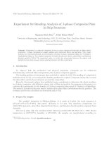
In this section, numerical results are carried
out to determine critical buckling loads of thinwalled channel beams with various configurations
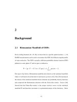
including boundary conditions, lay-ups. The material properties and geometry of thin-walled beams
are given in Table 2 and Fig. 2.
Firstly, in order to verify the present solution,
a simply-supported beam with isotropic channel
section (b1 = b2 = 14.5 cm, b3 = 30 cm, h1 =
h2 = h3 = 1.0 cm, E = 200 GPa and G = 80 GPa)
b3
y
x
h3
b2
h2
Figure
2. Geometry
of thin-walled
Figure
2. Geometry
of thin-walled
compositecomposite
channel beams
channel beams
Table 3. Critical buckling load (kN) of simply-supported beam
L (m)
Reference
Note
39
Present
Nguyen et al. [18]
4
1569.64
1552.57
Torsional buckling
6
772.43
772.43
Flexural buckling
8
434.50
434.50
Flexural buckling
Duong, N. N., et al. / Journal of Science and Technology in Civil Engineering
Table 2. Material properties of thin-walled beams
Material (MAT) properties
MAT.I
E1 (GPa)
E2 = E3 (GPa)
G12 = G13 (GPa)
G23 (GPa)
ν12 = ν13
MAT.II
144
9.65
4.14
3.45
0.30
141.9
9.78
6.13
4.8
0.42
is considered. The critical buckling load is presented in Table 3. It is clear that the present results are coincided with those obtained from [18]. Another verified example is also performed for
composite beams. The critical buckling load of channel beams (MAT.I, b1 = b2 = b3 = 10 cm,
h1 = h2 = h3 = 1.0 cm and L = 20b3 ) is showed in Table 4 and compared with [13]. Good agreement
is also found. It should be noted that the buckling load for plane strain state (ε s = 0) is bigger for
plane stress state (σ s = 0). This phenomenon can be explained by the fact that the plane strain state is
equivalent ignoring Poisson’s effect and causes the beams stiffer.
Table 3. Critical buckling load (kN) of simply-supported beam
Reference
L (m)
4
6
8
Present
Nguyen et al. [18]
1569.64
772.43
434.50
1552.57
772.43
434.50
Note
Torsional buckling
Flexural buckling
Flexural buckling
Table 4. Critical buckling load (105 N) of thin-walled channel beams
Lay-up
BC
Reference
S-S
(00 /00 /00 /00 )
(00 /900 /900 /00 )
Present (ε s = 0)
Present (σ s = 0)
Cortinez and Piovan [13]
2.631
2.617
2.674
1.603
1.595
1.635
C-F
Present (ε s = 0)
Present (σ s = 0)
Cortinez and Piovan [13]
0.932
0.929
0.947
0.658
0.656
0.670
C-S
Present (ε s = 0)
Present (σ s = 0)
Cortinez and Piovan [13]
4.979
4.952
5.058
2.884
2.869
2.941
C-C
Present (ε s = 0)
Present (σ s = 0)
Cortinez and Piovan [13]
9.364
9.310
9.503
5.270
5.240
5.371
40
Duong, N. N., et al. / Journal of Science and Technology in Civil Engineering
Secondly, the symmetric angle-ply channel beams with the various BCs and lay-ups are considered. The thickness of flanges and web are of 0.0762 cm, and made of asymmetric laminates that
consist of 6 layers ( η − η 3 ). The critical buckling load of channel beams (MAT.II, b1 = b2 = 0.6 cm,
b3 = 2.0 cm and L = 100b3 ) is showed in Table 5. It can be observed that the buckling load reduces
as lay-up increases for all BCs. From Table 5, it can be seen that there is a significant difference
between results of plane stress and plane strain state for beams with arbitrary angle. Available literatures indicate that plane stress assumption is more appropriate and widely used for composite beams
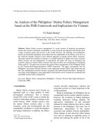
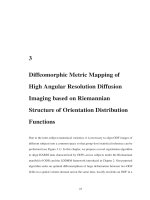
[23, 24, 28–30]. Figs. 3(a)–3(f) show first three buckling mode shape of S-S beams with [30/ − 30]3
angle-fly in flanges and web. It can be seen that the buckling mode 1, 2 and 3 are first flexural mode
in y-direction (Mode V), first and second torsional mode (Mode Φ) for both plane stress and plane
strain state.
Table 5. Critical buckling load (N) of thin-walled channel beams
Lay-up
BC
[0]
[15/ − 15]
[30/ − 30]
[45/ − 45]
[60/ − 60]
[75/ − 75]
[90/ − 90]
S-S
εs = 0
σs = 0
28.215
27.871
24.944
22.572
17.172
10.379
9.137
4.180
4.062
2.456
2.222
2.011
1.945
1.921
C-F
εs = 0
σs = 0
7.054
6.968
6.206
5.618
4.263
2.581
2.269
1.042
1.011
0.614
0.555
0.503
0.486
0.480
C-S
εs = 0
σs = 0
57.720
57.018
50.864
46.038
34.951
21.152
18.598
8.532
8.283
5.022
4.543
4.113
3.978
3.930
C-C
εs = 0
σs = 0
112.858
111.486
99.383
89.958
68.257
41.322
36.320
16.673
16.183
9.817
8.881
8.043
7.778
7.684
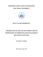
Finally, effect of length-to-height ratio on buckling behaviours of the thin-walled composite beams
is investigated. Figs. 4(a) and 4(b) show the critical buckling load of beams (MAT.II, b1 = b2 =
0.6 cm, b3 = 2.0 cm, h1 = h2 = h3 = 0.0762 cm and [45/ − 45]3 ). It can be seen that the buckling
load reduces as length-to-height ratio increases for all BCs.
4. Conclusions
Ritz method is applied to analyse buckling of thin-walled composite channel beams in this paper.
The theory is based on the classical theory. The governing equations are derived from Lagrange’s
equations. The critical buckling loads of thin-walled composite channel beams with various BCs are
obtained and compared with those of the previous works. The results indicate that:
- The effects of fiber orientation are significant for buckling behaviours of thin-walled channel beams.
- For thin-walled beams with arbitrary angle, the buckling loads for plane stress and for plane
strain state are significantly different.
41
Journal of Science and Technology in Civil Engineering
Journal
and
Technology in
in CivilEngineering
Engineering
Journal of
of Science
Science and
and Technology
Technology
Journal
of
Science
in Civil
Civil Engineering
Duong, N.Journal
N., et al.
/ Journal
of
Science
and Technology
in Civil Engineering
Journal
Scienceand
and
Technology
Civil
Engineering
ofofScience
Technology
inin
Civil
Engineering
(a) Mode shape 1: N01 = 17.172 N (e s = 0 )
(a) Modeshape
shape 1: N
17.172 N ((ee s =
N01 === 17.172
(a)
= 000))
(a)=Mode
Mode
shape 1:
1: N
17.172 N
N e ss =
01
01
0
(ss(a)
)
s (a)
Mode
shape
1:
=
17.172
N
N
=0 )0 )
Mode
shape
N (ε(es(se==
(a)
Mode
shape1:1:NN010101== 17.172
17.172 N
s 0)
((s(ss ss===000)))
(s(ss s==00) )
(b) Mode shape 1: N01 = 10.379 N
(b)
==10.379
(b) Mode
Modeshape
shape1:
1: N
10.379N
(b)
Mode
shape
1:
= 10.379
NN
NN01
0101
(b)
Mode
shape
1:
=
10.379
N
(b) Mode
Modeshape
shape1:1:N01N=01 10.379
= 10.379
NsN= 0)
(b)
N (σ
01
(c)
= 68.171 N
=00))
(c) Mode
Mode shape
shape 2:
2: N
02 = 68.171 N ((eess =
N 02
(c)(c)
Mode
shape
2:
N020202
=00 )
(ε s( e=ss 0)
Modeshape
shape2:
2: N
N
==68.171
NNN
(c)
Mode
2:
68.171
(c)
Mode
shape
=
68.171
N
e
=
(c)
Mode
shape
2:
=
68.171
N
(
N
e
(s s = )0)
0202
((ssss == 00))
(((sss(ssss ====000)0)))
s
(d)
Mode
shape
2:
==41.283
N
(d)
Mode
shape
2:
=02
N (σ
(d)Mode
Modeshape
shape
2:02NN
41.283
0202
(d)
2:N
=41.283
41.283
N sN= 0)
(e) Mode shape 3: N03 = 153.482 N (ε s = 0)
(f) Mode shape 3: N03 = 92.949 N (σ s = 0)
(d)Mode
Modeshape
shape2:2: NN 02==41.283
41.283NN
(d)
(d) Mode shape 2:N 02
N 02 = 41.283 N
10
10
10
10
Figure 3. First three buckling
10 mode shape of S-S beams
10
42
Deleted: .
Deleted:
. .
Deleted:
Deleted:
Deleted:
. .
Deleted:
Deleted:
Deleted:
. .. .
Deleted:
Deleted:
.
Deleted:
Deleted:
. .
Deleted:
Deleted:
. .
Deleted:
. .
Deleted:
Deleted:
Deleted:
.
Deleted:
Deleted: .. .
Deleted:
.
Deleted:
Deleted:
. . .
Deleted:
Figure
3. First
three
buckling
mode
shape
beams
Figure
3. First
three
buckling
mode
shape
of of
S-SS-S
beams
Finally,
effect
length-to-height
ratio
buckling
behaviours
thin-walled
Finally,
effect
of of
length-to-height
ratio
on on
buckling
behaviours
of of
thethe
thin-walled
composite
beams
is investigated.
Figs.
4(a)
show
critical
buckling
load
composite
beams
is investigated.
Figs.
4(a)
andand
(b)(b)
show
thethe
critical
buckling
load
of of
beams
(MAT.II,
= 2.0
h = 0.0762 cm and [ 45 / -45] ). It
= 0.6
beams
(MAT.II,
, b3, =b32.0
, h1, =h1h=2 =h2h=
cmcm
b1 =b1b=2 =b20.6
cmcm
3 =30.0762 cm and [ 45 / -45] ). 3It
3
Duong,
N.the
N.,buckling
et al. /load
Journal
of Science
Technology ratio
in Civil
Engineering
seen
load
reduces
as and
length-to-height
ratio
increases
BCs.
cancan
be be
seen
thatthat
the
buckling
reduces
as length-to-height
increases
forfor
all all
BCs.
(b)
sσs ss==s0=0 0
(b)(b)
e 0s0= 0
(a) (a)
(a)
εes s ==
Figure
4. Critical
buckling
load
thin-walled
composite
channel
beams
Figure
4. Critical
buckling
load
of of
thin-walled
composite
channel
beams
Figure
4.
Critical
buckling
load
of
thin-walled
composite
channel
beams
4. Conclusions
4. Conclusions
Deleted:
Deleted:
4 4
Commented
[A14]:
Commented
[A14]:
Chỉ s
lại không
BảngBảng
5 lại 5không
có ? có ?
Deleted:
.
Deleted:
.
Deleted:
.
Deleted:
.
Ritz
method
is applied
to analyse
buckling
of thin-walled
composite
channel
beams
Ritz
method
is applied
to analyse
buckling
of thin-walled
composite
channel
beams
- Theinpresent
solution
is theory
found
be on
appropriate
and
efficient
in
analysing
buckling
of
in this
paper.
istobased
on
classical
theory.
governing
equations
are
this
paper.
TheThe
theory
is based
thethe
classical
theory.
TheThe
governing
equations
areproblems
thin-walled
composite
channel
beams.
derived
from
Lagrange’s
equations.
The
critical
buckling
loads
of
thin-walled
derived from Lagrange’s equations. The critical buckling loads of thin-walled
composite
channel
beams
with
various
BCs
obtained
compared
with
those
composite
channel
beams
with
various
BCs
areare
obtained
andand
compared
with
those
of of
the
previous
works.
The
results
indicate
that:
the previous works. The results indicate that:
Acknowledgment
- The effects of fiber orientation are significant for buckling behaviours of thin-
- The effects of fiber orientation are significant for buckling behaviours of thinThis research
is funded by Vietnam National Foundation for Science and Technology Developwalled
channel
beams.
walled
channel
beams.
ment (NAFOSTED)
under
grant
number 107.02-2018.312.
- For
thin-walled
beams
with
arbitrary
angle,
buckling
loads
plane
stress
- For
thin-walled
beams
with
arbitrary
angle,
thethe
buckling
loads
forfor
plane
stress
and
for
plane
strain
state
are
significantly
different.
and for plane strain state are significantly different.
References - The present solution is found to be appropriate and efficient in analysing buckling
- The present solution is found to be appropriate and efficient in analysing buckling
problems
thin-walled
composite
channel
beams.
of of
thin-walled
composite
beams.
[1] Vlasov, V.problems
(1961).
Thin-walled
elastic
beams. channel
Israel
program
for scientific translations, Jerusalem.
Deleted:
Deleted:
the the
Deleted:
difference
Deleted:
difference
[2] Gjelsvik,
A. (1981). The theory of thin walled bars. Krieger Pub Co.
Deleted:
References
Deleted:
:
References
[3] Bauld Jr, N. R., Lih-Shyng, T. (1984). A Vlasov theory for fiber-reinforced beams with thin-walled open
1.
V.
Vlasov,
Thin-walled
elastic
beams.
Israel
program
for
scientific
translations,
V. Vlasov,
Thin-walled
elastic
beams.
Israel
program
for scientific translations,
cross1.sections.
International
Journal
of Solids
andLondon.
Structures,
20(3):277–297.
Jerusalem.
1961,
Oldbourne
Press,
Jerusalem.
1961,
Oldbourne
Press,
London.
[4] Gupta, R. K., Venkatesh, A., Rao, K. P. (1985). Finite element analysis of laminated anisotropic thinwalled open-section beams. Composite Structures, 3(1):19–31.
[5] Bank, L. C., Bednarczyk, P. J. (1988). A beam
theory for thin-walled composite beams. Composites
11 11
Science and Technology, 32(4):265–277.
[6] Pandey, M. D., Kabir, M. Z., Sherbourne, A. N. (1995). Flexural-torsional stability of thin-walled composite I-section beams. Composites Engineering, 5(3):321–342.
[7] Sherbourne, A. N., Kabir, M. Z. (1995). Shear strain effects in lateral stability of thin-walled fibrous
composite beams. Journal of Engineering Mechanics, 121(5):640–647.
[8] Lee, J., Kim, S.-E. (2001). Flexural–torsional buckling of thin-walled I-section composites. Computers
& Structures, 79(10):987–995.
[9] Lee, J., Kim, S.-E. (2002). Lateral buckling analysis of thin-walled laminated channel-section beams.
Composite Structures, 56(4):391–399.
[10] Lee, J., Kim, S.-E., Hong, K. (2002). Lateral buckling of I-section composite beams. Engineering Structures, 24(7):955–964.
[11] Cortínez, V. H., Piovan, M. T. (2002). Vibration and buckling of composite thin-walled beams with shear
deformability. Journal of Sound and Vibration, 258(4):701–723.
43
:
Duong, N. N., et al. / Journal of Science and Technology in Civil Engineering
[12] Shan, L., Qiao, P. (2005). Flexural–torsional buckling of fiber-reinforced plastic composite open channel
beams. Composite Structures, 68(2):211–224.
[13] Cortínez, V. H., Piovan, M. T. (2006). Stability of composite thin-walled beams with shear deformability.
Computers & Structures, 84(15-16):978–990.
[14] Kim, N.-I., Shin, D. K., Kim, M.-Y. (2007). Improved flexural–torsional stability analysis of thin-walled
composite beam and exact stiffness matrix. International Journal of Mechanical Sciences, 49(8):950–
969.
[15] Kim, N.-I., Shin, D. K. (2009). Dynamic stiffness matrix for flexural-torsional, lateral buckling and free
vibration analyses of mono-symmetric thin-walled composite beams. International Journal of Structural
Stability and Dynamics, 9(03):411–436.
[16] Vo, T. P., Lee, J. (2009). On sixfold coupled buckling of thin-walled composite beams. Composite
Structures, 90(3):295–303.
[17] Vo, T. P., Lee, J. (2009). Flexural–torsional coupled vibration and buckling of thin-walled open section
composite beams using shear-deformable beam theory. International Journal of Mechanical Sciences, 51
(9-10):631–641.
[18] Nguyen, T.-T., Thang, P. T., Lee, J. (2017). Flexural-torsional stability of thin-walled functionally graded
open-section beams. Thin-Walled Structures, 110:88–96.
[19] Nguyen, T.-T., Thang, P. T., Lee, J. (2017). Lateral buckling analysis of thin-walled functionally graded
open-section beams. Composite Structures, 160:952–963.
[20] Nguyen, T.-T., Lee, J. (2018). Flexural-torsional vibration and buckling of thin-walled bi-directional
functionally graded beams. Composites Part B: Engineering, 154:351–362.
[21] Nguyen, N.-D., Nguyen, T.-K., Vo, T. P., Nguyen, T.-N., Lee, S. (2019). Vibration and buckling behaviours
of thin-walled composite and functionally graded sandwich I-beams. Composites Part B: Engineering,
166:414–427.
[22] Lee, J. (2001). Center of gravity and shear center of thin-walled open-section composite beams. Composite Structures, 52(2):255–260.
[23] Lee, J. (2005). Flexural analysis of thin-walled composite beams using shear-deformable beam theory.
Composite Structures, 70(2):212–222.
[24] Lee, J., Lee, S.-h. (2004). Flexural–torsional behavior of thin-walled composite beams. Thin-Walled
Structures, 42(9):1293–1305.
[25] Nguyen, T.-T., Kim, N.-I., Lee, J. (2016). Analysis of thin-walled open-section beams with functionally
graded materials. Composite Structures, 138:75–83.
[26] Nguyen, T.-T., Kim, N.-I., Lee, J. (2016). Free vibration of thin-walled functionally graded open-section
beams. Composites Part B: Engineering, 95:105–116.
[27] Lee, J., Kim, S.-E. (2002). Free vibration of thin-walled composite beams with I-shaped cross-sections.
Composite Structures, 55(2):205–215.
[28] Sheikh, A. H., Asadi, A., Thomsen, O. T. (2015). Vibration of thin-walled laminated composite beams
having open and closed sections. Composite Structures, 134:209–215.
[29] Nguyen, N.-D., Nguyen, T.-K., Vo, T. P., Thai, H.-T. (2018). Ritz-based analytical solutions for bending, buckling and vibration behavior of laminated composite beams. International Journal of Structural
Stability and Dynamics, 18(11):1850130.
[30] Li, J., Huo, Q., Li, X., Kong, X., Wu, W. (2014). Vibration analyses of laminated composite beams
using refined higher-order shear deformation theory. International Journal of Mechanics and Materials
in Design, 10(1):43–52.
44