Carbon Dioxide Storage and Sequestration in Unconventional Shale Reservoirs
Bạn đang xem bản rút gọn của tài liệu. Xem và tải ngay bản đầy đủ của tài liệu tại đây (531.55 KB, 9 trang )
Journal of Geoscience and Environment Protection, 2015, 3, 7-15
Published Online March 2015 in SciRes. /> />
Carbon Dioxide Storage and Sequestration
in Unconventional Shale Reservoirs
S. Sina Hosseini Boosari1, Umut Aybar2, Mohammad O. Eshkalak2
1
West Virginia University, Morgantown, WV, USA
Petroleum and Geosystems Engineering Department, The University of Texas at Austin, Austin, TX, USA
Email:
2
Received 16 February 2015; accepted 14 March 2015; published 20 March 2015
Copyright © 2015 by authors and Scientific Research Publishing Inc.
This work is licensed under the Creative Commons Attribution International License (CC BY).
/>
Abstract
Carbon Dioxide (CO2) storage and sequestration in unconventional shale resources has been attracting interest since last couple of years due to the very unique characteristics of such formations have made them a feasible option for this object. Shale formations are found all around the
world and the conventional assets are easily accessible, and also the huge move of operators toward developing unconventional reservoirs during past years leaves many of such formations
ready for sequestering CO2. Today, the use of long horizontal wells that are drilled on a pad has the
lowest amount of environmental footprint in which for storage and sequestration purpose also
provides much more underground pore spaces available for CO2. In this paper we study the state
of the art of the technology of CO2 storage and sequestration and provide different and fresh look
for its complex phenomena from a mathematical modeling point of view. Moreover, we hope this
study provides valuable insights into the use of depleted shale gas reservoirs for carbon sequestration, which as a result, a cleaner atmosphere will be achieved for the life of our next generations. Also, we present that the depleted shale gas reservoirs are very adequate for this purpose as
they already have much of the infrastructure required to perform CO2 injection available in sites.
Keywords
Carbon Dioxide Sequestration, Shale Reservoirs, Modeling and Simulation, Clean Environment
1. Introduction
Geologic formations and abundant reservoirs have attracted much attention within the engineering community
for the purpose of reducing carbon dioxide of the atmosphere through storing and sequestration process in recent
years. Worldwide energy demand is supported by the significant role of conventional and unconventional resources of oil and gas. This huge dependency has resulted in critical environmental issues such as increased CO2
How to cite this paper: Boosari, S.S.H., Aybar, U. and Eshkalak, M.O. (2015) Carbon Dioxide Storage and Sequestration in
Unconventional Shale Reservoirs. Journal of Geoscience and Environment Protection, 3, 7-15.
/>
S. S. H. Boosari et al.
emission known as the greenhouse gas, and for the purpose of having a clean atmosphere for next generations,
CO2 storage and sequestration has gotten a common procedure for this purpose. During the last decade, energy
equations are changed due to the advances obtained in drilling and fracturing of unconventional reservoirs both
in the US and worldwide. The main simple difference between conventional and unconventional resources is the
fact that unconventional are scattered all around the world but conventional exist just in some parts of the world.
This strongly means that since unconventional are everywhere on the map then the CO2 sequestration in such
reservoirs are very reasonable and economically feasible [1] [2].
Shale gas is mostly methane that is trapped within the shale formations. Shale is located thousands of feet below earth surface. Gas-productive shale formations in the continental US are of thermogenic or biogenic origin
and are found in Paleozoic and Mesozoic rocks. Shale is a fine-grained sedimentary rock that, when deposited as
mud, can collect organic matter. When the organic matter decays over time, petroleum and natural gas products
are formed within the rock’s pores. Shales typically hold dry gas, but some formations produce liquid products
as well. Conventional gas reservoirs form from the migration of natural gas from an organic-rich source into
permeable reservoir rock. Unconventional gas-rich shales, however, generally function as both the source and
reservoir for natural gas. Shales have low permeability, which means that trapped gas cannot move easily within
the rock. Because of this, a technique called hydraulic fracturing is employed to produce the natural gas. This
unique characteristic benefits the sequestration of CO2. Hydraulic fracturing cracks the shale rock through the
injection of water, sand, and chemicals at high pressure.
Underground storage and sequestration of carbon dioxide involves the process of injecting highly pressurized
CO2 into the formations considering the capability of the rock to permanently keep it from leaking toward the
earth surface. There are five applicable options for safely sequestering the carbon dioxide into the geologic formations. Saline formations, basalts, un-mineable coal seams, conventional oil and gas reservoirs and depleted
unconventional shale resources are technically studied during the course of this paper. As of now, considering
the advances gained through last couple of years in carbon management, scientists have proposed the following
statements: 1) estimating CO2 storage capacity +/− 30 percent in geologic formations; 2) ensuring 99 percent
storage permanence; 3) improving efficiency of storage operations; and 4) developing Best Practices Manuals [3]
[4]. These technologies will lead to future CO2 management for coal-based electric power generating facilities
and other industrial CO2 emitters by enabling the storage and utilization of CO2 in all storage types.
In the U.S., Nuttall et al. (2005) estimated the CO2 sequestration capacity in the organic-rich Devonian black
shales in the Big Sandy gas field of Eastern Kentucky to be about 6.8 Gt. To illustrate the importance of shale
formations for CO2 storage in Europe, the Dutch resource of shale gas own an estimation of between 48,000 and
230,000 Bcm. If one assumes that technology can be developed to store 1 m3 of CO2 for 1 m3 of CH4 produced,
and that only one percent of the resource can be recovered, a substantial 480 - 2300 Bcm of CO2, corresponding
to 0.9 to 4.35 Gton CO2, could be stored. In this paper we further analyze the developments, advances and issues
related to methods that are in practice and authors will provide alternative technologies that are given a fresh
look toward the classical research.
2. Shale Gas Resources in the U.S. and Worldwide
In 2000 shale gas provided only 1% of U.S. natural gas production; by 2010 it is over 20% and the U.S. government’s Energy Information Administration predicts that by 2035, 48.9% of the United States’ natural gas
supply will come from shale gas. These trends obviously demonstrate that we can expect that shale gas will
greatly expand worldwide energy supply. Further, China is estimated to have the world’s largest shale gas reserves. Some researches show that shale gas production in the USA and Canada could help Europe to be less
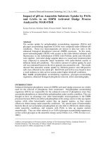
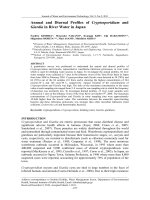
dependent to Russian and Persian Gulf countries. Figure 1 shows that unconventional resources (Shale Gas,
Tight Gas, Coalbed Methane) containing hydrocarbon are almost all over the world. The most common form of
unconventional natural gas is shale gas. In this study, the main focus will be on storage and sequestration in
shale gas.
3. Shale Reservoirs Modeling and Simulation
Reservoir simulation and modeling of unconventional resources have been given much more attention over the
past years. Many numerical and analytical models have been developed and extensive reservoir studies have
been conducted. Commercial reservoir simulators are also improved to handle and capture fluid flow behavior
8
S. S. H. Boosari et al.
Shale Gas
Tight Gas
Coalbed Mathane
Figure 1. Worldwide shale gas resources.
and natural gas production from unconventional assets, such as shale. However, developing an unconventional
reservoir model that accounts for all pressure dependent phenomena and integrates all physics incorporated in
gas flow for tight formations is still a challenging target for the petroleum industry. Among analytical and semianalytical methods, works done by [5] [6] have provided comprehensive progress in the modeling of shale gas
reservoirs. Many authors, such as [7] [8], have used numerical simulation techniques in order to model different
aspects of unconventional shale reservoirs.
Analytical reservoir models are widely employed because of their relative simplicity compared to numerical
approaches. The aim of analytical solutions is to provide a simple solution which covers the fundamental physics of the phenomenon. In order to accomplish these goals, the analytical solution must have some simplifying
assumptions. Having constant and/or homogeneous rock and fluid properties (density, compressibility, permeability, and viscosity) are the common assumptions for analytical solutions. The purpose of these assumptions is
to linearize the partial differential equations arising from modeling of fluid flow in a reservoir; in our case, the
diffusion equation. There are two methods in the literature customarily preferred for analytical fluid flow solutions: one is proposed by [9] [10], which has solution in time domain; while the other techniques are introduced
by [11] and use Laplace transformation for solutions. Following these two solution techniques, researchers have
proposed analytical solutions for hydraulically fractured unconventional reservoirs [12] [13]. Analytical reservoir models are applicable for quite accurate, simple and robust simulations to evaluate production performances
of hydraulically fractured unconventional reservoirs.
Eshkalak et al. investigated the geo-mechanical properties of Marcellus shale. They generated a common
source for securing these rock mechanical properties, geomechanical well logs, and studied various characteristics, such as minimum horizontal stress, young, bulk shear modulus, as well as poison’s ratio that play an important role in defining the stress profiles of an unconventional reservoir. Moreover, having an access to rock
geomechanical properties will enhance the understanding of the parameters, such as conductivity and pressure
dependency of permeability [14]-[17].
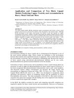
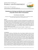
In Figure 2, the natural gas production for past years and projections for following years are given. The shale
gas is the only form of natural gas whose production amount is increasing. All other types of natural gas are either decreasing or remaining constant. It can be easily said that in the future the USA and world natural gas
production is the shale gas, the Y axis is trillion cubic feet [1].
Generally, two-phase fluid flow of water and gas in a dual-permeability model is considered in constructing
the geologic model of shale gas reservoirs. The dual-permeability model considers the intercommunication be-
9
S. S. H. Boosari et al.
U. S. dry natural gas production
trillion cubic feet
History
2011
Projections
35
30
25
Shale gas
20
15
Tight gas
Non-associated offshore
10
Alaska
Coalbed methane
5
Associated with oil
Non-associated onshore
0
1990
1995
2000
2005
2010
2015
2020
2025
2030
2035
Source: U. S. Energy Information Administration, Annual Energy Outlook 2013 Early Release
Figure 2. Natural gas production outlook.
tween the inter-granular void spaces in contrast to the dual-porosity model. Also, this model considers flow in
two domains including the matrix and fracture. This model allows the transfer of both gas and water between the
matrix and fracture domains, gas velocity in the matrix and fracture domains is calculated with the Equations (1)
and (2):
K gm
Dgm
∇Pg + m ∇C gm
−
vgm =
µg
Cg
where vg is gas velocity, K g
(1)
K gf
Dgf
(2)
−
∇Pg + f ∇C gf
vgf =
µg
Cg
is gas permeability, Dg is gas diffusivity, Pg is gas pressure, C g is gas con-
centration, and µ g is gas viscosity. Subscripts m and f represent matrix and fracture domains. Velocity of the
water flowing in matrix and fracture are determined with Equations (3) and (4), respectively:
Km
− w ∇Pwm
vwm =
µw
where, vw is water velocity, K w
(3)
Kf
− w ∇Pwf
vwf =
µw
is water permeability, Pw is water pressure, and µ w is water viscosity.
(4)
3.1. Flow in Matrix
The equations of gas transport thus are simplified for matrix domain as shown in Equation (5):
m m
∂ Cg Pg
∂t Z
Pgm K gm
RT mf
Pgm Dgm Pgm
∇
∇Pgm + Dgm ∇
+ m
∇Cgm −
qw + qwm
=
Z µg
Z
Z
M
C
g
(
10
)
(5)
S. S. H. Boosari et al.
where Z is the gas compressibility factor, R is the gas constant, T is temperature, M is gas molecular weight, and
qg is gas mass flow rate per unit matrix-block volume. Subscript m and f represent the exchange between matrix
and fracture. For the water phase, the same equation is shown in Equation (6):
Km
RT mf
∂ ∅ m swm
qw + qwm
∇ w ∇Pwm −
=
∂t Bw
Bw µ w
M
(
)
(6)
where ∅ m is matrix porosity, sw is water saturation, and Bw is water compressibility factor.
3.2. Flow in Fracture
After some manipulation and simplifications, the gas flow governing equation in fracture becomes as the following Equation (7):
f
f
∂ C g Pg
∂t Z
Pgf K gf
Pgf Dgf Pgf
∇
∇Pgf + Dgf ∇
+ m
∇C gf
=
Z µg
Z
Z
C
g
RT mf
q − qwm
+
M w
(
)
(7)
For the water phase, Equation (8) represents the related formula.
∂ ∅ f sw
∂t Bw
f
Kf
RT mf
qw − qwm
∇ w ∇Pwf +
=
B
M
µ
w
w
(
)
(8)
Equations (9) to (12) represent the auxiliary relations used in the solution method.
Cgm = ∅ f swm
(9)
Cgf = ∅ f swf
(10)
sgm + swm =
1
(11)
sgf + swf =
1
(12)
4. What We Have Learnt from CO2 Sequestration in Saline Aquifers
CO2 emission reduction becomes one of the main concerns of the world; hence deep saline aquifers can be used
as CO2 storage [18] to decrease CO2 emission. Aquifers are the favorable storage places comparing to depleted
reservoirs and coal seams, mainly because of safety issues [19] [20]. Poorly-sealed abounded wells are reducing
the safety of storage capability of depleted reservoirs, while water-bearing permeable rock nature of saline aquifers is increasing the safety factor [21].
To perform a successful CO2 sequestration project in saline aquifers, monitoring and verification of storing
process is a must. Underground distribution of CO2 needs to be monitored during the life of project. It is essential to identify when the minimum volume and saturation of CO2 has been reached in the storage reservoir.
Lithology, geomechanics and geology of the storage reservoir is main elements which drive CO2 detection
capability within the reservoir. Having said that, it must also be noted that all of these reservoir characteristics
have some level of uncertainties. There is no doubt about that these uncertainties may have an impact on CO2
distribution detection in the reservoir. Therefore, these uncertainty elements also need to be taken into account
for the CO2 sequestration and CO2 distribution detection planning stages [22].
CO2 detectability also relies on the phase in which CO2 is injected in the storage reservoir. CO2 is customarily
injected as a liquid form to be able to transform to a supercritical phase. Supercritical state has both a liquid and
a gas characteristic; hence supercritical fluid expands like a gas, while keeping its density as a liquid level. CO2
density is adequate to fill the pores at depths lower than 2600 ft.
State of CO2, and the environment into which it is sequestered, have a significant bearing on the detectability
of CO2. Typically, CO2 is injected as a liquid which transforms to a supercritical fluid [23]. In this state, it has
properties of both a liquid and a gas so that it expands like a gas, but with a density of a liquid. At depths below
800 m, CO2 density is high enough to allow efficient filling of pore space. There is also a reduction in the
buoyancy difference between the CO2 and other pore fluids.
11
S. S. H. Boosari et al.
Miscibility is another important characteristic which varies with CO2 sequestration conditions. As it is a
known fact that CO2 and natural gas are miscible, therefore CO2 is able to relocate water in the pores. However,
since our interest here is CO2 sequestration in saline aquifers, multiphase relationship of CO2 and the aquifer
dictates the pore space volume which can be filled by CO2 [23] [24].
5. CO2 Sequestration Capacity of Shale
Coming from the extremely tight and low permeability nature of shale reservoirs, to produce from or to inject
any fluid into shale reservoirs is tough. However, technological improvements in hydraulic fracturing technique
made these reservoirs producible. Hydraulic fracturing basically opens artificial flow channels for reservoir fluid
to flow with cracking the formation via pumping of highly pressurized fluid into the formation. Once these shale
reservoirs depleted, existing fractures in the reservoir could be storage for CO2 sequestration. Another advantage
of shale reservoirs is that they do not require capital expense cost such as new well drilling which is the case for
saline aquifers [25].
Viability of CO2 storage in shale reservoirs can be predicted by reservoir models, since it is critical to identify
CO2 storage capacity of the reservoir. There are two major criteria while performing feasibility study for CO2
sequestration in shale formations. The first criterion is the diffusivity which gives an idea about formation deliverability. The first criterion in this regard is gas adsorption/desorption characteristics of shale formations. It is
an ongoing study and many researchers claim that CO2 may adsorb the shale formation more favorable than
methane.
Storage capacity of shale formations for CO2 storage is promising. It is also claimed that CO2 injection time in
shale reservoirs would be much faster than the methane production from these reservoirs. In addition, it is estimated that around 14.5 billion tons of CO2 can be sequestrated into shale formations in the next two decades.
The estimated capacity is almost half of the U.S. CO2 emissions from power plants within the next 20 years,
which is equal to 20% of total expected CO2 emission of the U.S.
Based on numerical investigation, it concluded that the maximum CO2 storage capacity for eastern U.S [24]
shale gas is 1.12 million metric tons per square kilometer, and the sorbed CO2 storage capacity is estimated to be
0.72 million metric tons per square kilometer. The total CO2 storage capacity of organic-rich shales at supercritical conditions as a function of pore pressure was measured by [26] by considering the pore compressibility and
sorption effects. The results state that kerogen, the organic part of the shale, acts as a molecular sieve and accounts for the gas sorption on shales. The sorption capacity of shales is affected by its TOC content, clay minerals and micropore structure. There is a large body of literature investigating the sorption capacity [27].
6. CO2 Trapping Mechanisms
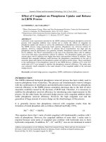
Trapping mechanisms are important in CO2 sequestration feasibility studies. Four trapping mechanisms are
present to our knowledge which are given in Figure 3, and can be named as: mineral trapping, solubility trapping, residual CO2 trapping, and structural/stratigraphic trapping. Trapping time is considered up to ten thousand
years same as the nuclear storage projects. To give an idea about 10,000 years consideration time, it has been
11,000 years up to today since the last ice age [28].
The most common type of trapping mechanisms is geological structures for CO2 storage in depleted reservoirs.
Deep saline aquifers also have structural trapping mechanism coming from their depositional environment.
When upward migration of CO2 is blocked by impermeable rock layer, CO2 is trapped due to buoyancy effect.
Moving from geological structures for trapping, solubility type of trapping takes place when CO2 dissolved in
formation water [28]. Reservoir pore pressure and temperature, along with the formation water salinity are the
key elements for solubility trapping. CO2 solubility rises with increasing pressure, on the other hand decreases
with increasing temperature and salinity. With this mechanism CO2 is trapped as a liquid phase sinking under the
gas phase due to gravitational forces. Solubility type of trapping is secure and favorable for CO2 storage [29].
All in all, CO2 sequestration feasibility studies are not depending on one unique trapping mechanism. It is
concluded that different geophysical characterizations will be necessary throughout the life of the project. For
instance, earlier and later stages of the sequestration project might be sensitive to different characteristics, hence
it is suggested that time lapse surveys must be performed through the life of the project to confirm sequestrated
CO2 is trapped securely [17] [30].
12
S. S. H. Boosari et al.
7. Active Carbon Capture and Sequestration (CCS) Projects Worldwide
Carbon Capture and Sequestration projects are mainly performed in the U.S. and Europe, pie chart distribution
of the world CCS projects is given in Figure 4. Canada, Australia and New Zealand, and China are also other
major players of CCS projects [31]-[33].
100
% trapping contribution
Structural &
stratigraphic
trapping
Residual CO2
trapping
Increasing storage security
Solubility
trapping
Mineral
trapping
0
1
10
100
1000
Time since injection stops (years)
10,000
Figure 3. Schematic representation of the security of CO2
trapping mechanisms over time.
1%
1%
USA
8%
1%
Australia and New Zeland
China
East Asia
36%
India
25%
Japan
Eastern Europe
Europe
Middle East
3%
Africa
3%
11%
3%
7%
South Africa
Canada
1%
Figure 4. Countries with active CCS program.
13
S. S. H. Boosari et al.
8. Conclusions
Unconventional shale reservoirs are main hydrocarbon resources of today’s world, they are developed for oil
and gas production. However, depleted unconventional shale reservoirs can be good candidates for CO2 sequestration and storage operations. Extremely low permeability nature of shale reservoir might seem like their lack,
but on the other hand decent amount of CO2 can absorb on shale fracture surfaces. Existing natural and hydraulic fracture networks in shale reservoirs made these reservoirs attractive to permanent CO2 storage projects. That
being said, when it comes to reservoir modeling for CO2 storage, many characteristic factors need to be taken
into account such as buoyancy, heterogeneity of shale reservoirs, and the existence of formation water, because
they will directly affect the storage capacity of the particular reservoir.
In conclusion, our extended literature review shows that shale reservoirs are good candidates for CO2 storage
with the capacity of 5 to 10 kg/t per formation. These results verify the feasibility of CO2 sequestration in shale
reservoirs. It can be stated that the long term feasibility of CO2 storage in shale reservoirs needs to be extended.
However, the information available to our knowledge manifests that shale reservoirs can be good storage candidates for permanent CO2 storage, therefore studies need to be focused on to make these projects practical. It is
concluded that unconventional shale reservoirs have many favorable characteristics for CO2 storage, and it is
expected that these reservoirs will become very attractive for CO2 sequestration projects all around the world in
the very near future.
References
[1]
National Energy Technology Laboratory (2010) Carbon Sequestration Atlas of the United States and Canada. 3rd Edition, the U.S. Department of Energy, Washington DC, p162. 2.
[2]
Li, Z.W., Dong, M.Z., Li, S.L. and Huang, S. (2006) CO2 Sequestration in Depleted Oil and Gas Reservoirs—Caprock
Characterization and Storage Capacity. Energy Conversion and Management, 47, 1372-1382.
/>
[3]
Rice University, News and Media Relations (2011) Shale Gas and U. S. National Security. Rice University News and
Media Relations Team, Huston.
[4]
Brown, M.L. (2009) Analytical Trilinear Pressure Transient Model for Multiply Fractured Horizontal Wells in Tight
Shale Reservors. M.Sc. Thesis, Colorado School of Mines, Golden.
[5]
Aybar, U., Eshkalak, M.O., Sepehrnoori, K. and Patzek, T.W. (2014) The Effect of Natural Fracture’s Closure on
Long-Term Gas Production from Unconventional Resources. Journal of Natural Gas Science and Engineering, 21,
1205-1231. />
[6]
Esmaili, S., Kalantari-Dahaghi, A. and Mohaghegh, S.D. (2012) Forecasting, Sensitivity and Economic Analysis of Hydrocarbon Production from Shale Plays Using Artificial Intelligence & Data Mining. SPE Canadian Unconventional Resources Conference, Calgary, 30 October-1 November 2012, SPE162700.
[7]
Kalantari-Dahaghi, A. and Mohaghegh, S.D. (2011) Numerical Simulation and Multiple Realizations for Sensitivity
Study of Shale Gas Reservoirs. SPE Production and Operations Symposium, Oklahoma City, 27-29 March 2011, SPE
141058.
[8]
Carslaw, H.S. and Jaeger, J.C. (1959) Conduction of Heat in Solids. 2nd Edition, Clarendon Press, Oxford.
[9]
Van Everdingen, A.F. and Hurst, W. (1949) The Application of the Laplace Transformation to Flow Problems in Reservoirs. Journal of Petroleum Technology, 1, 305-324. />
[10] Aybar, U., Eshkalak, M.O., Sepehrnoori, K. and Patzek, T.W. (2014) Long Term Effect of Natural Fractures Closure on
Gas Production from Unconventional Reservoirs. SPE Eastern Regional Meeting, Charleston, 21-23 October 2014, SPE
171010.
[11] Ozkan, E., Raghavan, R.S. and Apaydin, O.G. (2010) Modeling of Fluid Transfer from Shale Matrix to Fracture Network. SPE Annual Technical Conference and Exhibition, Florence, 19-22 September 2010, SPE 134830.
[12] Torcuk, M.A., Kurtoglu, B., Fakcharoenphol, P. and Kazemi, H. (2013) Theory and Application of Pressure and Rate
Transient Analysis in Unconventional Reservoirs. SPE Annual Technical Conference and Exhibition, New Orleans, 30
September-2 October 2013, SPE 166147.
[13] Eshkalak, M.O., Mohaghegh, S.D. and Esmaili, S. (2014) Geomechanical Properties of Unconventional Shale Reservoirs. Journal of Petroleum Engineering, 2014, Article ID: 961641.
[14] Eshkalak, M.O., Mohaghegh, S.D. and Esmaili, S. (2013) Synthetic, Geomechanical Logs for Marcellus Shale. Digital
Energy Conference and Exhibition, The Woodlands, 5-7 March 2013, SPE 163690.
14
S. S. H. Boosari et al.
[15] OmidvarEshkalak, M. (2013) Synthetic Geomechanical Logs and Distributions for Marcellus Shale. MSc Thesis, West
Virginia University, Morgantown.
[16] Michael, K., Arnot, M., Cook, P., Ennis-King, J., Funnell, R., Kaldi, J., Kirste, D. and Paterson, L. (2009) CO2 Storage in
Saline Aquifers I—Current State of Scientific Knowledge. Energy Procedia, 1, 3197-3204.
/>[17] Aybar, U., Yu, W., Eshkalak, M., Sepehrnoori, K. and Patzek, T. (2015) Evaluation of Production Losses from Unconventional Shale Reservoirs. Journal of Natural Gas Science and Engineering, 23, 509-516.
/>[18] JafarGandomi, A. and Curtis, A. (2011) Detectability of Petrophysical Properties of Subsurface CO2-Saturated Aquifer
Reservoirs Using Surface Geophysical Methods. The Leading Edge, 30, 1112-1121.
[19] Eshkalak, M.O., Aybar, U. and Sepehrnoori, K. (2014) An Integrated Reservoir Model for Unconventional Resources,
Coupling Pressure Dependent Phenomena. Eastern Regional Meeting, Charleston, 21-23 October 2014, SPE 171008.
[20] White, D. and Johnson, J. (2009) Integrated Geophysical and Geochemical Research Programs of the IEA GHG Weyburn-Midale CO2 Monitoring and Storage Project. Energy Procedia, 1, 2349-2356.
/>[21] Gale, J. and Freund, P. (2001) Coal-Bed Methane Enhancement with CO2 Sequestration Worldwide Potential. Environmental Geosciences, 8, 210-217. />[22] Benson, S., Hoversten, G.M., Gasperikova, E. and Haines, M. (2004) Monitoring Protocols and Life-Cycle Costs for
Geologic Storage of Carbon Dioxide. Proceedings of the 7th International Conference on Greenhouse Gas Control
Technologies, Vancouver, 5-9 September 2004, 1259-1264.
[23] Benson, S. and Cole, D.R. (2008) CO2 Sequestration in Deep Sedimentary Formations. Elements, 4, 325-331.
/>[24] Eshkalak, M.O., Aybar, U. and Sepehrnoori, K. (2014) An Economic Evaluation on the Re-Fracturing Treatment of the
US Shale Gas Resources. Eastern Regional Meeting, Charleston, 21-23 October 2014, SPE 171009.
[25] Bear, J. (1972) Dynamics of Fluids in Porus Media. Elsevier, Amsterdam.
[26] Godec, M., Koperna, G., Petrusak, R. and Oudinot, A. (2013) Potential for Enhanced Gas Recovery and CO2 Storage
in the Marcellus Shale in the Eastern United States. International Journal of Coal Geology, 118, 95-104.
/>[27] Kang, S.M., Fathi, E., Ambrose, R., Akkutlu, I. and Sigal, R. (2011) Carbon Dioxide Storage Capacity of Organic-Rich
Shales. SPE Journal, 16, 842-855. />[28] Eshkalak, M.O., Al-Shalabi, E.W., Sanaei, A., Aybar, U. and Sepehrnoori, K. (2014) Simulation Study on the CO2Driven Enhanced Gas Recovery with Sequestration versus the Re-Fracturing Treatment of Horizontal Wells in the U.S.
Unconventional Shale Reservoirs. Journal of Natural Gas Science and Engineering, 21, 1015-1024.
/>[29] Eshkalak, M.O., Al-Shalabi, E.W., Sanaei, A., Aybar, U. and Sepehrnoori, K. (2014) Enhanced Gas Recovery by CO2
Sequestration versus Re-Fracturing Treatment in Unconventional Shale Gas Reservoirs. Abu Dhabi International Petroleum and Exhibition and Conference, Abu Dhabi, 10-13 November 2014, SPE 172083.
[30] Aybar, U. (2014) Investigation of Analytical Models Incorporating Geomechanical Effects on Production Performance
of Hydraulically and Naturally Fractured Unconventional Reservoirs. MSc Thesis, The University of Texas at Austin,
Austin.
[31] Gensterblum, Y., Busch, A. and Krooss, B.M. (2014) Molecular Concept and Experimental Evidence of Competitive
Adsorption of H2O, CO2 and CH4 on Organic Material. Fuel, 115, 581-588.
/>[32] Polson, D., Curtis, A. and Vivalda, C. (2012) The Evolving Perception of Risk during Reservoir Evaluation Projects
for Geological Storage of CO2. International Journal of Greenhouse Gas Control, 9, 10-23.
/>[33] Eke, P.E., Naylor, M., Haszeldine, S. and Curtis, A. (2011) CO2-Brine Surface Dissolution and Injection: CO2 Storage
Enhancement. SPE Projects, Facilities and Construction, 6, 41-53. />
15