Clay mineralogy and geochemistry of three offshore wells in the southwestern Black Sea, northern Turkey: The effect of burial diagenesis on the conversion of smectite to illite
Bạn đang xem bản rút gọn của tài liệu. Xem và tải ngay bản đầy đủ của tài liệu tại đây (5.77 MB, 19 trang )
Turkish Journal of Earth Sciences
Turkish J Earth Sci
(2016) 25: 592-610
© TÜBİTAK
doi:10.3906/yer-1601-10
/>
Research Article
Clay mineralogy and geochemistry of three offshore wells in the southwestern Black Sea,
northern Turkey: the effect of burial diagenesis on the conversion of smectite to illite
Yinal N. HUVAJ*, Warren D. HUFF
Department of Geology, University of Cincinnati, Cincinnati, Ohio, USA
Received: 14.01.2016
Accepted/Published Online: 24.05.2016
Final Version: 01.12.2016
Abstract: The conversion of smectite to illite has long been studied by numerous researchers because of its importance as a diagenetic
metric. Interpreting the pressure, temperature, and age of the sequences in which this conversion occurs provides the possibility to
identify the historical maturation parameters of hydrocarbon sources. The Black Sea Basin is known to be an area that can provide
source rocks for oil and gas production. The purpose of this study was to determine the clay minerals and their abundances, to establish
a stratigraphic correlation among three wells, which is useful to select specific stratigraphic horizons for hydrocarbon exploration, and
to predict paleotemperature ranges in the wells by using the conversion of clay minerals. The determination of the clay mineralogy and
chemical composition of the three wells in the Black Sea Basin was done by several methods of analysis. These methods include powder
X-ray diffraction (XRD), X-ray fluorescence spectroscopy (XRF), and environmental scanning electron microscopy (ESEM). All 54
samples were processed by XRD and XRF and 6 representative samples were selected for ESEM analysis. Based on the XRD results, the
clay minerals determined in the samples are illite, smectite, and mixed-layer illite/smectite (I/S), which are the most abundant minerals
calculated by the method described in Underwood and Pickering, plus kaolinite and chlorite. The chemical results of major oxides
acquired from XRF analyses show that the changes in Na2O and K2O, which are the main actors in the conversion of smectite to illite,
do not gradually increase or decrease. Since the Black Sea Basin is considered a rift basin, the maximum temperature ranges of the
conversion were calculated by considering the maximum and minimum depths of the samples. These temperature ranges are 111–154
°C, 147–208 °C, and 48–59 °C for Well-1, Well-2, and Well-3, respectively.
Key words: Black Sea, burial diagenesis, clay mineralogy, geochemistry, illite, smectite
1. Introduction
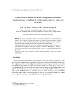
Studying the stratigraphy of the Black Sea Basin (Figure
1) and its associated clay minerals is important for
hydrocarbon exploration. The basin has long been known
to be an area that can provide source rocks for oil and
gas production. Because of the high cost of geophysical
exploration of offshore areas, clay mineralogical studies
become even more important as an aid to understanding
diagenetic and thermal conditions responsible for
hydrocarbon generation. The clay mineralogy of the
three wells drilled by the Turkish Petroleum Corporation
(TPAO) has not been determined before. Determining the
changes in clay minerals may provide useful information,
such as the extent to which burial diagenesis versus
primary detrital input most accurately reflects the nature
of the depositional environment, and thus understanding
such conditions will help geologists to make a connection
between the temperature that allows the changes in
clay minerals and the temperature of occurrence of
hydrocarbon resources. Determining of changes in clay
*Correspondence:
592
minerals and understanding the mechanism that causes to
such changes can also be useful for petroleum companies
for interpreting the source rock occurrence zones. For
these reasons, studying the clay minerals in the Black Sea
Basin area has become important in recent years.
Clay mineral analysis has been used as a tool in
terms of predicting paleoenvironmental conditions,
stratigraphic correlation, and hydrocarbon generation
zone identification to determine target interval and
diagenetic conditions of hydrocarbon-bearing formations
since the 1950s (Weaver, 1958, 1960; Hower et al., 1976;
Hoffman and Hower, 1979). Since then, clay minerals have
been used to determine the hydrocarbon emplacement
time and for petroleum system analysis (Yariv, 1976;
Liewig et al., 1987; Hamilton et al., 1989; Kelly et al., 2000;
Drits et al., 2002; Jiang, 2012).
The structure of smectite changes with increasing burial
depth; then the mineral disappears under burial conditions
and the possible mechanism is a beneficiation of degraded
and fragmental mineral lattices by the gradual fixation
HUVAJ and HUFF / Turkish J Earth Sci
Figure 1. Tectonic settling of Turkey and Black Sea (slightly modified after Okay, 2008).
of potassium and magnesium to form illite and chlorite,
respectively (Burst, 1959). In the Upper Cretaceous shale
section in Cameroon, smectite is converted to illite with
increasing depth of burial (Dunoyer de Segonzac, 1964).
The conversion of smectite to illite depends on the effects of
burial diagenesis (Perry and Hower, 1970); they concluded
that there is a linear relationship between the increasing
potassium content of the clay-size fraction and the
decrease of expandability. Therefore, potassium availability
is important in the transformation of smectite to illite. For
example, during burial diagenesis potassium feldspar and/
or mica decompose and potassium is released (Hower et
al., 1976). Freed and Peacor (1992) expressed the view
that the conversion of smectite to illite requires fixation
of K in interlayer sites and this conversion is concomitant
with the substitution of Al for Si in tetrahedral sites.
Others (e.g., Fowler and Young, 2003) suggested that the
conversion proceeds by means of dissolution of a smectite
and reprecipitation as an illite.
2. Geological setting
The Black Sea is one of a number of ocean basins around
the Tethyside orogenic belt (Görür, 1988). It is a remnant
of the Tethys Ocean, which existed between the two
megacontinents, Gondwana in the south and Laurasia in
the north of today’s Turkey (Okay et al., 1996; Okay, 2008).
The area for this study hosts the three offshore wells in the
southwest of Black Sea along the Turkish margin (Figure
1) and is located in the tectonic unit called the “İstanbul
Zone”, which is a part of the western Pontides region in
northern Turkey, as described in Yılmaz et al. (1997),
Okay and Tüysüz (1999), and Okay (2008). The İstanbul
Zone was located in the Odessa shelf, today’s Ukraine,
between the Moesian platform and the Crimea until the
593
HUVAJ and HUFF / Turkish J Earth Sci
Lower Cretaceous. During the Aptian–Albian time in the
late part of the Lower Cretaceous, approximately 120 Ma
ago, it was rifted and started to move southward (Görür,
1988; Okay et al., 1994) and during the Early Eocene, the
İstanbul Zone collided with the Sakarya Zone (Okay and
Tüysüz, 1999).
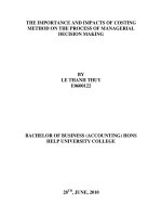
The stratigraphic sequence of the İstanbul Zone
(Figure 2) starts with a Precambrian crystalline basement
(Okay et al., 1994, 1996; Okay and Tüysüz, 1999; Okay,
2008). This unit is characterized by gneiss, amphibolite,
metavolcanic rocks, meta-ophiolite, and Precambrianaged granitoids (Chen et al., 2002; Yigitbas et al., 2004;
in Istanbul region
(west)
Ustaömer et al., 2005; Okay, 2008). This basement is
unconformably overlain by a continuous, well-developed
(Okay et al., 1996; Okay, 2008), and transgressive (Okay
and Tüysüz, 1999) sedimentary sequence from Ordovician
to Carboniferous in age. This sequence was folded and
deformed during the Variscan/Hercynian orogeny in the
Carboniferous (Okay et al., 1996; Okay and Tüysüz, 1999;
Okay, 2008). Stratigraphically, the Paleozoic sequence of
the İstanbul Zone shows different characteristics in the west
and the east portions of the terrane. In the western part,
Carboniferous units mainly consist of more than 2000 m
of deep sea turbidites forming a sandstone/shale sequence,
in Zonguldak region
(east)
Eocene
Alpide Deformation
Paleocene
Cretaceous
Jurassic
Cimmeride Deformation
Triassic
Permian
Variscan/ Hercynian
Deformation
Carboniferous
Devonian
Silurian
Ordovician
LEGEND
Precambrian
Marl
Limestone
Flysch
Mudstone
Sandstone
Conglomerate-Sandstone
Conglomerate-Sandstone-Mudstone
Basaltic-Andesitic Lava
Metamorphic Units
Figure 2. Illustration of stratigraphic sequence of İstanbul Zone (not to scale)
(modified after Okay and Tüysüz, 1999).
594
HUVAJ and HUFF / Turkish J Earth Sci
and pelagic limestones with radiolarian cherts. The age
of the limestones and cherts is Visean (Mississippian)
of the Early Carboniferous and the age of the turbidites
is Namurian (Pennsylvanian) of the Late Carboniferous.
In the eastern part, however, the Carboniferous is
characterized by Visean shallow marine carbonates and
a Namurian and Westphalian (Pennsylvanian) paralic
coal series (Okay and Tüysüz, 1999; Okay, 2008). Another
difference between these two parts is that the Variscan/
Hercynian orogeny started earlier and was stronger in the
western part than in the eastern one (Okay and Tüysüz,
1999). The Paleozoic sequence is unconformably overlain
by the Triassic sedimentary sequence, which is welldeveloped in the east of the İstanbul Zone. This sequence
shows a typical transgressive development, about 800 m
thick. It starts with red sandstones and basaltic lava flows,
continues with shallow marine marls, limestones, and then
deep marine limestones, and ends with deep sea sandstones
and shales. In the western part of the İstanbul Zone, the
Jurassic and Lower Cretaceous rocks are absent, and the
Triassic sequence is unconformably overlain by Upper
Creataceous clastic rocks and limestones, and Eocene
neritic limestones unconformably overlie the Mesozoic
units. However, there are Middle Jurassic to Eocene rocks
marked by small unconformities in the eastern part of the
İstanbul Zone. The Jurassic flysch and Upper Cretaceous
limestones, clastics, and marl units overlie to the Triassic
rocks, and this sequence is overlain by Palaeocene and
Eocene pelagic limestones and flysch (Okay and Tüysüz,
1999; Okay, 2008).
2.1. Geology of the three offshore wells
Based on the privacy policy of the Turkish Petroleum
Corporation, the names of the wells have been numbered
and symbolized, and formation names also symbolized.
The samples acquired from the Turkish Petroleum
Corporation are mostly from the KS formation. All
samples of Well-2 (Well “KC”) and Well-3 (Well “A”)
are from the KS formation, two samples of Well-1 (Well
“I”) are from the GR formation, and one sample is from
the AKV formation. Samples of Well-1 and Well-2 have
been selected from marl units that show slightly different
characteristics such as color and clay content. Nine of
the twelve samples of Well-3 have been selected from
mudstone, one sample of the Well-2 is from claystone, and
the others are from marl lithologies.
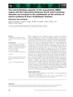
Well-1 was drilled in the Black Sea near the western
border of the Central Pontides tectonic unit of Turkey.
This location is approximately 25 km from the eastern
boundary of the İstanbul Zone (Figure 3).
Nineteen samples were selected from Well-1 (Figure
4). Well-2 is located approximately 60 km west of Well1 and is represented by 23 samples (Figure 5). Twelve
samples have been received from Well-3 (Figure 6). This
well is located approximately 320 km west of Well-2.
3. Materials and methods
All 54 cutting samples were provided by the Turkish
Petroleum Corporation Research Center and the samples
were hand-picked to ensure representative lithology or
different characteristics of the same lithology at different
depths. A Siemens D-500 X-ray diffractometer using
Cu-Kα radiation was used to obtain XRD patterns of the
samples (Figure 7). All samples were prepared by using the
smear mount method described by Moore and Reynolds
(1997). The particle size of the analyzed materials is <2 µm
and this particle size has been achieved by following the
particle size separation methods described also by Moore
and Reynolds (1997).
Chemical analyses were performed with a Rigaku 3070
wavelength-dispersive X-ray fluorescence spectrometer.
Samples were finely ground in a tungsten carbide ball
mill canister for 7–8 min. After this grinding process
sample grains became less than 5 µm in size, which is an
appropriate size to prepare XRF pellets. The powdered
sample was then compressed into thin pellets using the
Spex 3624B X-Press machine. Prepared XRF pellets were
placed into a 55 °C oven for 24 h until analyzed.
A number of different types of grains such as apatite,
biotite, and quartz phenocrysts were photographed and
chemically analyzed with a Phillips XL-30 field emission
gun (FEG) environmental scanning electron microscope
(Figure 8). Each cutting sample was sieved through a No.
100 sieve (0.15 mm/0.059 in) to remove coarse grains and
a No. 200 sieve (0.075 mm/0.029 in) to remove clay-sized
particles. During the sieving processes cutting samples
were washed with water and after sieving they were left in
a 60 °C oven for drying. After they dried, individual grains
were handpicked under the microscope and stuck onto
the adhesive surface of an ESEM sample holder by using
a special fiber.
4. Results and discussion
Based on the XRD patterns, the clay minerals determined
in the samples are illite, smectite, mixed-layer illite/smectite
(I/S), kaolinite, and chlorite. The percentages of these
minerals were calculated by using the method described
in Underwood and Pickering (1996). According to the
calculations, illite is the dominant mineral in all three wells.
The average illite percentages are 51%, 51%, and 46% in
Well-1, Well-2, and Well-3, respectively. Smectite is the
second most abundant mineral as 25%, 19%, and 18% in
Well-1, Well-2, and Well-3, respectively (Figure 9). On the
other hand, as can be seen in the XRD patterns there is a
mixed-layer illite/smectite (I/S) phase in almost all samples.
However, the I/S phase is not dominant and individual
illite and smectite minerals also exist independently from
the mixed-layer phase. This unusual character of I/S has
not been discussed widely in many papers before. As
595
HUVAJ and HUFF / Turkish J Earth Sci
Figure 3. Location map of the three offshore wells on the tectonic unit map of Turkey (close-up view of the red-lined
rectangular area in Figure 1) (slightly modified from Okay and Tüysüz, 1999; and Yilmaz et al., 1997).
discussed in Moore and Reynolds (1997), the existence of
the I/S in the air-dried XRD pattern causes a slight shifting
on the illite 002 peak position in the glycolated pattern. In
our samples, there is no such a shifting effect after glycol
treatment. It demonstrates that the I/S phase in our samples
is not dominant, and the dominant phases are discrete illite
and smectite. Based on the clay mineral assemblage and
percentages discussed above, it can be concluded that the
samples contain both detritic primary illite as individual
phases and diagenetic (or neoformative) illite as mixedlayer illite/smectite phases. This conclusion is supported
by the graphics of illite crystallinity (Kübler index (KI))
measurements shown in Figure 10. These measurements have
been obtained by using the method described in Jaboyedoff
596
et al. (2001). As is known, the KI is used for understanding
the degree of diagenesis and low-grade metamorphism
(Jaboyedoff et al., 2001). As discussed in Kübler (1967),
the epizone–anchizone boundary was defined at 0.25 Δ2θ
CuKα, and the anchizone–diagenesis boundary was defined
at 0.42 Δ2θ CuKα. The KI values of many of the samples are
in the epizone and anchizone and the values of some of the
samples are in the diagenetic zone. In Well-1 two samples
do not give a KI value, because these samples are from the
faulted/thrust zones. Based on the KI interpretation, the
mixed-layer I/S formation has started in each well. However,
the unusual patterns (sharp fluctuations) of the KI graphics
may be caused by the existence of the diagenetic and detritic
forms of illite together.
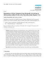
HUVAJ and HUFF / Turkish J Earth Sci
Well-1
Middle Eocene
KS Formation
Depth (m.)
508
L.Eocene
600
Campanian
Maastrichtian
Late
Eocene
Middle Eocene
KS Formation
AKV
Formation
Mid.
Eocene
MARL: Gray, silty, contains fine conglomerates
MARL: Green, contains thin sandstone/siltstone layers
800
SANDSTONE: Gray, has calcitic cement, contains carbonate minerals and
metamorphic quartz, feldspar
1000
1264
LIMESTONE: Beige, contains gravels, formed as canal facies
MARL: Beige, contains bioclastic limestone layers
TUFF: Light green, rigid
Fault
MARL: Light gray, silty-sandy, contains gravels and thin sandstone layers
1415
1700
Fault
LIMESTONE: Beige, clayey
TUFF: Green, altered, vitreous
MARL: Light green, low silts, contains limestone layers
1800
1948
MARL: Beige, silty, contains coal particles, and thin sandstone layers
2116
MARL: Light green, low silts, contains limestone layers
2160
ANDESITE/ANDESITIC TUFF: Gray-light green, altered
2180
2220
Figure 4. Illustration of columnar section of Well-1 (not to scale).
Late
Eocene
Well-1
Depth (m.)
800
MARL:Light gray, a little silty
910
SANDSTONE: Beige, high quartz content, contains black volcanic particles
980
1144 MARL: Gray, a little silty
1160
1194
1270 LIMESTONE: Light gray, contains Nummulites fossils
1308
1344 MARL: Olive green in color, contains a little carbonaceous material
1376 MARL: Light green
1412
1476 MARL: Very light green, silty
Middle
Eocene
2084
Early-Middle
Eocene
2508
KS Formation
Middle Eocene
1164
1608
1708
1770
1900
1948
1984
2030
2220
2348
2384
2440
2464
2512
2600
2800
SILTSTONE: Greenish gray, slightly carbonaceous
MARL: Light green, silty and sandy, contains dispersed Nummulites fossils
SANDSTONE: Gray, contains quartz and carbonaceous rock particles, well-compacted
TUFF: Light green, vitreous
CLAYSTONE: Very light beige, slightly carbonaceous
MARL: Light beige, silty, partly clayey
MARL: Gray-light gray, a little silty
MARL: Very light beige, contains no silts
SHALE: Dark brown, contains organic materials
MARL: Gray-light gray, clayey, contains no silts
3000
3100
Figure 5. Illustration of columnar section of Well-2 (not to scale).
597
HUVAJ and HUFF / Turkish J Earth Sci
Well-3
Lower
Oligocene
Depth (meters)
MUDSTONE: Gray, silty, contains coal particles
DOLOMICRITE
MUDSTONE: Gray, silty, contains coal particles
MUDSTONE:
MUDSTONE:Light
Lightgray,
gray,silty
silty
MUDSTONE/MARL: Beige, clayey, low silty,
contains coal particles
MARL: Light green, massive, silty
LIMESTONE: White, fossilliferous, low clayey, contains pyrites
TUFF
LIMESTONE: Beige, highly contains echinoids, benthic forams
Figure 6. Illustration of columnar section of Well-3 (not to scale).
The key point is the mirror-like changing patterns of
smectite and illite amounts. The illite percentage generally
increases while the smectite percentage decreases with
increasing burial depth. This change suggests that
the conversion of smectite to illite takes place in the
sedimentary sequences in each well. Two major changes,
however, take place in Well-1: the first change is seen after
1400 m depth and the second is seen after 1800 m depth.
At the first point, the illite percentage dramatically falls
below 10% and the smectite percentage rises above 90%.
At the second point, the smectite percentage dramatically
falls below 20% and the illite percentage rises above 60%.
According to the interpretations, there are two main
faults detected at around 1400 m and 1800 m depths.
The dramatic changes in clay mineralogy can possibly be
explained by the effects of these two main faults (Figure
11).
The chemical results of major oxides acquired from XRF
analyses (Table 1) show changes in K2O, Na2O, SiO2, and
Al2O3 with the increase in burial depth in determination
of the conversion of smectite to illite (Figures 12 and 13).
The Na2O and K2O values, as seen in the graphics, do not
gradually increase or decrease. Those kinds of irregular
patterns indicate that changes in weight percentages of
Na2O and K2O values are not simply responsible for the
conversion of smectite to illite.
In order to understand the source materials of samples
(sediments) of each well, Zr/TiO2 ratio against depth
598
graphics (Figure 13) and Zr/TiO2 ratio versus Nb/Y ratio
diagrams, which were firstly suggested by Winchester
and Floyd (1977), would be helpful (Figure 14). In Well2 and Well-3, changes in Zr/TiO2 ratios with increasing
depth do not show an important difference (Table 2). The
source rock of samples of these two wells is andesite, and
so trends in Zr/TiO2 ratios are reasonable because the
sources are composed only of andesitic rocks. In Well-1,
the ratio shows different trends and the source rocks of the
samples of this well are multiple. This result indicates that
samples in the circles in the Zr/TiO2 against depth graphic
of Well-1 are from three different sources. The source rock
of the samples in the upper circle is andesite; the source
rocks of the samples in the middle circle are trachyandesite
and dacite/rhyodacite. The source rock of the samples in
the bottom circle is dacite/rhyodacite. Chemical changes
in K2O and Na2O with increasing burial depth show that
the Na2O percentage is slightly increasing in Well-1 and
Well-2, but slightly decreasing in Well-3, and the K2O
percentage shows slight decreasing trends in all the wells.
Al2O3 percentages are almost constant in Well-1 and Well2, and there is a slight decrease in Well-3. SiO2 percentages
are slightly decreasing in Well-1 and Well-3 and slightly
increasing in Well-2.
The SEM-EDS analyses show that the studied sediment
sequence contains some minerals that originated from
volcanic rocks. The determination of such minerals
like biotite and apatite in SEM analyses is evidence of
HUVAJ and HUFF / Turkish J Earth Sci
Well-1
1230
Well-1
530
550
°C
400
°C
Well-1
2150
Sm
550
°C
400
°C
Sm
K
I
Q
Glycol
K+Ch Q+I
10
15
20
2Θ CuKα
25
30
Q
I
K
5
10
Glycol
Q+I
400
°C
°C
Q+I
I
K+Ch
Q
Air
Air
20
25
2Θ CuKα
30
5
10
15
20
25
2Θ CuKα
30
Well-2
3050
Well-2
1690
°C
400
Glycol
K+Ch
I
15
Well-2
880
550
°C
K
Air
5
I
Sm
I
550
Sm
550
o
C
400
o
C
550 °C
Sm
400 °C
Sm
I
I
K
Q
I
K
Glycol
I
Q+I
Glycol
Q+I
K+Ch
I
Glycol
Q+I
K
I
K+Ch
Q
Q
K+Ch
20
25
Air
Air
5
10
15
20
2Θ CuKα
25
30
5
10
15
20
2Θ CuKα
Well-3
140
25
30
5
10
15
2Θ CuKα
Well-3
360
550
30
Well-3
570
550
°C
°C
550
°C
400
°C
Sm
Sm
400
°C
400
I
K
Glycol
I
K+Ch
I
K
Q+I
Q
I
10
15
20
2Θ CuKα
25
Glycol
Sm
I
Q+I
Glycol
K+Ch
Q
K
Q
K+Ch
I
Air
5
°C
Q+I
Air
Air
30
5
10
15
20
2Θ CuKα
25
30
5
10
15
20
2Θ CuKα
25
30
Figure 7. XRD diffractograms of some representative samples (C: Calcite, Ch: Chlorite, I: Illite, K: Kaolinite,
Q: Quartz, Sm: Smectite).
599
HUVAJ and HUFF / Turkish J Earth Sci
Figure 8. ESEM images and chemistry of some phenocrysts (A and B: Biotite phenocrystals from 570 m depth of Well-3, C: An apatite phenocrystal from
240 m depth of Well-3, D: An apatite phenocrystal from 570 m. of Well-3, E: A quartz phenocrystal from 880 m of Well-2).
600
HUVAJ and HUFF / Turkish J Earth Sci
Well-1 (I)
5%
6%
13%
51%
25%
Well-2 (KC)
7%
7%
16%
Well-3 (A)
19%
13%
10%
51%
46%
13%
18%
%I
% Sm
% I/S
%K
% Ch
Figure 9. Average clay mineral percentages in each well (I: illite; Sm: smectite; I/S: mixed-layer illite/
smectite; K: kaolinite; Ch: chlorite).
Well-1(I)
0
KI
0.0
0.2
0.4
0.6
0.8
Depth (m)
500
1000
Well-2 (KC)
1500
0
2000
Anchizone
0.0
Diagenesis
KI
0.2
0.4
0.6
Depth (m)
Epizone
Well-3 (A)
0.4
0.6
0.8
1000
1500
2000
2500
3000
100
Depth (m)
0.2
500
2500
0
0.0
KI
3500
200
Epizone
Anchizone
Diagenesis
300
400
500
600
Epizone
Anchizone
Diagenesis
Figure 10. Illite crystallinity (Kübler index) values of the samples against depth graphic (zone boundaries are
used from Kübler, 1967).
601
HUVAJ and HUFF / Turkish J Earth Sci
Percentage
Well-1
0
0
10
20 30
40 50
60 70
80 90 100
400
Depth (m)
800
Percentage
Well-2
0
1200
0
10
20 30
40 50
60 70
80 90 100
400
1600
800
2000
Depth (m)
1200
2400
Percentage
Well-3
0
0
10
20 30
40 50
60 70
80 90 100
2000
2400
2800
100
3200
2000
Depth (m)
1600
300
400
500
600
%1
%Sm
%LS
%K
%Ch
Figure 11. Changes in clay mineral percentages against depth.
transportation of materials that originated from volcanic
source rocks into the depositional area. The SEM-EDS
analyses are also used for interpreting the source of the
detritic clay minerals and the source of possible ash falls
that have been deposited in the basin and become a source
of smectite in the sediment sequence.
The conversion of smectite to illite becomes possible
with the substitution of Na ions by K ions with the
increasing of burial depth. According to the early studies
by Perry and Hower (1970), Hower et al. (1976), and
Pearson and Small (1988), the source of K ion in the
system is generally the decomposition of K-feldspars and/
or mica minerals, and then the tetrahedral substitution
of Al+3 for Si+4 produces appropriate space for fixing of
the K ion. This mechanism, which is explained by Perry
602
and Hower (1970) and Hower et al. (1976), is also known
as the diagenetic transformation model. According to
Nadeau et al. (1985), there is another mechanism, called
the neoformation or dissolution/precipitation model for
conversion of smectite to illite crystals. The assumption
made here is that the composition in the sedimentary
sequence is constant. In other words, the sediments in
the depositional environment have come from a single
source and the changes in the sequence occur within the
depositional area’s own dynamics. The K2O values of the
samples in each well do not change very much and so the
K+ concentration has substantially been conserved in the
depositional sequence, but has shown minor fluctuation
in some depths of each well. Moreover, the addition of
the detritic materials commonly from andesitic volcanic
HUVAJ and HUFF / Turkish J Earth Sci
Table 1. XRF results of major oxides (wt%) (values of Well-1 [Well-I]).
Sample
depth (m)
SiO2
TiO2
Al2O3
Fe2O3
MnO
MgO
CaO
Na2O
% K2O
P2O5
LOI
530
45.1
0.60
11.2
4.66
0.07
2.38
13.5
0.47
4.24
0.12
17.9
580
47.1
0.61
11.7
4.70
0.07
2.34
11.4
0.63
4.19
0.12
17.0
620
43.4
0.54
10.2
3.96
0.07
2.05
14.2
0.56
4.96
0.09
19.8
720
44.2
0.54
10.5
4.07
0.07
2.10
13.7
0.63
4.89
0.09
19.1
830
43.0
0.55
10.1
4.17
0.07
2.09
15.1
0.58
4.61
0.10
19.7
960
42.2
0.55
10.3
4.29
0.07
2.19
14.4
0.55
4.93
0.10
20.4
1060
45.4
0.58
10.7
4.41
0.07
2.25
13.4
0.56
4.18
0.12
18.4
1160
43.8
0.53
10.4
4.15
0.08
2.14
13.8
0.58
4.58
0.10
19.7
1230
44.4
0.53
9.8
3.97
0.08
2.08
15.7
0.59
4.09
0.11
18.6
1320
24.7
0.26
7.5
1.96
0.11
1.41
27.9
0.76
3.80
0.13
31.7
1380
23.6
0.25
6.9
1.76
0.06
1.37
29.7
0.60
3.26
0.15
32.5
1480
33.5
0.33
7.3
2.19
0.04
2.11
25.0
0.77
2.55
0.05
26.4
1560
34.8
0.32
8.1
2.19
0.04
1.50
23.6
0.87
2.97
0.05
26.0
1620
41.3
0.41
10.4
2.99
0.03
1.71
17.2
1.99
3.28
0.06
21.6
1720
38.7
0.46
10.6
4.34
0.06
1.51
17.0
0.61
3.96
0.08
21.9
1820
45.5
0.51
10.8
3.44
0.07
1.92
13.8
0.82
3.82
0.08
18.2
1910
37.1
0.38
9.5
2.48
0.07
1.71
19.7
1.07
3.39
0.09
25.0
2060
43.3
0.48
9.7
3.39
0.08
1.88
16.4
0.71
3.51
0.09
19.6
2150
43.2
0.45
10.5
2.93
0.09
1.97
16.6
0.98
3.30
0.09
20.2
Table 1. (Continued). (values of Well-2 [Well-KC]).
Sample
depth (m)
SiO2
TiO2
Al2O3
Fe2O3
MnO
MgO
CaO
Na2O
K2O
P2O5
LOI
830
41.0
0.59
10.59
4.81
0.07
2.57
14.2
0.49
4.96
0.11
20.7
880
39.7
0.56
10.14
4.54
0.07
2.40
15.1
0.49
5.39
0.09
21.6
950
41.5
0.59
10.81
4.56
0.06
2.61
13.3
0.66
5.26
0.10
20.7
1050
40.4
0.57
10.78
4.62
0.07
2.52
14.2
0.61
5.24
0.09
21.0
1160
42.3
0.62
11.24
4.92
0.07
2.73
13.0
0.67
4.91
0.11
19.5
1240
40.7
0.57
12.60
5.80
0.13
2.70
15.3
0.61
3.05
0.06
19.3
1320
36.4
0.54
9.40
4.91
0.10
2.41
18.1
1.52
4.33
0.11
22.1
1420
40.4
0.55
11.07
4.84
0.09
2.45
13.5
1.48
4.94
0.09
20.4
1520
41.7
0.56
10.75
4.73
0.09
2.33
13.8
0.68
4.99
0.10
20.2
1600
42.3
0.57
10.64
4.88
0.09
2.36
14.6
0.71
4.42
0.09
19.5
1690
41.5
0.55
10.23
4.53
0.08
2.24
15.4
0.67
4.54
0.09
20.1
603
HUVAJ and HUFF / Turkish J Earth Sci
Table 1. (Continued).
1800
45.9
0.60
11.57
4.89
0.12
2.46
11.7
0.76
4.20
0.13
17.5
1960
44.8
0.54
12.60
5.62
0.22
2.13
14.0
0.65
2.45
0.07
16.7
2000
47.1
0.57
12.80
6.06
0.20
2.19
12.3
0.66
2.35
0.08
15.8
2080
44.7
0.54
12.00
5.49
0.08
2.22
12.3
0.74
2.92
0.12
18.7
2200
44.0
0.52
11.40
4.98
0.07
2.15
13.5
0.62
2.75
0.07
19.6
2300
42.7
0.53
11.70
4.99
0.06
2.25
14.7
0.61
2.71
0.07
19.1
2430
44.6
0.57
12.40
5.45
0.08
2.14
11.5
1.08
3.13
0.08
16.0
2550
47.9
0.58
12.90
6.17
0.15
2.28
10.6
0.76
2.84
0.08
15.7
2680
43.7
0.51
11.34
4.72
0.20
2.22
11.0
0.99
4.78
0.14
19.6
2790
48.6
0.60
12.20
5.45
0.18
2.44
9.3
0.66
3.60
0.17
16.4
2890
41.8
0.58
10.89
4.58
0.07
2.52
13.2
0.73
5.26
0.10
20.3
3050
43.1
0.58
10.74
4.65
0.07
2.47
13.7
0.75
4.49
0.12
19.4
Table 1. (Continued). (values of Well-3 [Well-A]).
Sample
depth (m)
SiO2
TiO2
Al2O3
Fe2O3
MnO
MgO
CaO
Na2O
K2O
P2O5
LOI
530
45.1
0.60
11.19
4.66
0.07
2.38
13.5
0.47
4.24
0.12
17.9
580
47.1
0.61
11.74
4.70
0.07
2.34
11.4
0.63
4.19
0.12
17.0
620
43.4
0.54
10.23
3.96
0.07
2.05
14.2
0.56
4.96
0.09
19.8
720
44.2
0.54
10.51
4.07
0.07
2.10
13.7
0.63
4.89
0.09
19.1
830
43.0
0.55
10.06
4.17
0.07
2.09
15.1
0.58
4.61
0.10
19.7
960
42.2
0.55
10.27
4.29
0.07
2.19
14.4
0.55
4.93
0.10
20.4
1060
45.4
0.58
10.71
4.41
0.07
2.25
13.4
0.56
4.18
0.12
18.4
1160
43.8
0.53
10.35
4.15
0.08
2.14
13.8
0.58
4.58
0.10
19.7
1230
44.4
0.53
9.78
3.97
0.08
2.08
15.7
0.59
4.09
0.11
18.5
1320
24.7
0.26
7.47
1.96
0.11
1.41
27.9
0.76
3.80
0.13
31.7
1380
23.6
0.25
6.90
1.76
0.06
1.37
29.7
0.60
3.26
0.15
32.5
1480
33.5
0.33
7.28
2.19
0.04
2.11
25.0
0.77
2.55
0.05
26.4
1560
34.8
0.32
8.07
2.19
0.04
1.50
23.6
0.87
2.97
0.05
26.0
1620
41.3
0.41
10.43
2.99
0.03
1.71
17.2
1.99
3.28
0.06
21.6
1720
38.7
0.46
10.57
4.34
0.06
1.51
17.0
0.61
3.96
0.08
21.9
1820
45.5
0.51
10.76
3.44
0.07
1.92
13.8
0.82
3.82
0.08
18.2
1910
37.1
0.38
9.49
2.48
0.07
1.71
19.7
1.07
3.39
0.09
25.0
2060
43.3
0.48
9.68
3.39
0.08
1.88
16.4
0.71
3.51
0.09
19.6
2150
43.2
0.45
10.53
2.93
0.09
1.97
16.6
0.98
3.30
0.09
20.2
604
HUVAJ and HUFF / Turkish J Earth Sci
Well-1 (I)
400
Weight (%)
0 5 10 15 20 25 30 35 40 45 50 55 60
600
Depth (m)
800
1000
Well-2 (KC)
1200
600
1400
900
1600
1200
1800
Depth (m)
2000
2200
Depth (m)
Well-3 (A)
100
150
200
250
300
350
400
450
500
550
600
Weight (%)
0 5 10 15 20 25 30 35 40 45 50 55 60
Weight (%)
1500
1800
2100
2400
0 5 10 15 20 25 30 35 40 45 50 55 60
2700
3000
3300
K2O%
Na2O%
Al2O3%
SiO2%
Figure 12. Changes in K2O, Na2O, Al2O3, and SiO2 percentages against depth.
Zr/TiO2
0.00 0.01 0.02 0.03 0.04 0.05
0
250
500
750
1000
1250
1500
1750
2000
2250
Well-3
0.00
0
Depth (m)
100
0.01
Zr/TiO2
0.02
0.03
0.04
0.05
Well-2
Depth (m)
Depth (m)
Well-1
0.00
0
250
500
750
1000
1250
1500
1750
2000
2250
2500
2750
3000
3250
Zr/TiO2
0.01
0.02
0.03
0.04
0.05
200
300
400
500
600
Figure 13. Changes in Zr/TiO2 ratio against increasing depth in each well.
605
HUVAJ and HUFF / Turkish J Earth Sci
10
Well-1
Zr/TiO2
Phonolite
Comendite
Pantellerite
1
Rhyolite
Trachyte
0.1
Rhyodacite
Dacite
10
Trachyandesite
Well-2
Andesite
0.01
Andesite. Basalt
Alkali basalt
Basanite
Nephelinite
1
Comendite
Pantellerite
Phonolite
0.001
0.01
10
0.1
1
Nb/Y
10
Zr/TiO2
Sub-alkaline basalt
Rhyolite
0.1
Well-3
1
Zr/TiO2
Trachyandesite
Andesite
0.01
Sub-alkaline basalt
0.001
0.01
Trachyte
Rhyodacite
Dacite
Basanite
Alkali basalt Nephelinite
Andesite. Basalt
Phonolite
Comendite
Pantellerite
Rhyolite
0.1
Trachyte
Rhyodacite
Dacite
0.1
Nb/Y
1
10
Trachyandesite
Andesite
0.01
Andesite. Basalt
Alkali basalt
Basanite
Nephelinite
Sub-alkaline basalt
0.001
0.01
0.1
Nb/Y
1
10
Figure 14. Zr/TiO2 vs. Nb/Y diagrams.
terrestrial source rocks into the depositional area can
disrupt the neoformation mechanism and the burial
diagenesis becomes a more reasonable explanation for the
transformation process of smectite to illite.
According to Velde (1995), the geothermal gradient
is about 25–35 °C/km in continental margins, 30–40 °C/
km in basins formed in midcontinent regions, and 40–60
°C/km in rift areas. The Black Sea Basin is considered a
rift basin (Görür, 1988; Okay, 2008); thus the geothermal
gradient in the region can be thought of as about 40–60
°C/km. The maximum sample depths of the wells are
2150 m, 3050 m, and 570 m in Well-1, Well-2, and Well-3,
respectively. As a result, the maximum temperature ranges
of the conversion of smectite to illite are about 111–154
°C in Well-1, 147–208 °C in Well-2, and 48–59 °C in Well3. These temperature ranges are for the maximum depths,
and it is known that the conversion of smectite to illite can
start at shallower depths. Thus, the average temperature
606
ranges for the conversion can be estimated as 56–77 °C in
Well-1, 74–104 °C in Well-2, and 24–30 °C in Well-3.
Based on the similarity of the lithologies, changes
in clay mineral percentages with depth, and major and
trace element chemistries of the samples, a stratigraphic
correlation pattern between the three wells is proposed
(Figure 15). Lithologies in Well-1 and Well-2 show quite
similar characteristics. The bottom sequence (similar
lithologic packages) of Well-3 is also similar to the top
sections of the other two wells. Chemical fingerprints
of that sequence of Well-3, however, do not exactly
match similar sequences of the other wells (the changing
patterns of K2O and Na2O are slightly different from
Figure 12 because of using different scales). The sequence,
as a suggestion, should be seen somewhere above the
uppermost part of Well-2 (blank uncolored section at the
top of Well-2). Another explanation should be made for
the subsequences seen in purple (the pattern with slashes
HUVAJ and HUFF / Turkish J Earth Sci
Table 2. XRF contents of some trace elements (ppm) on depth.
Well-1
Well-2
Well-3
Depth (m)
Nb
Y
Zr
Depth (m)
Nb
Y
Zr
Depth (m)
Nb
Y
Zr
530
8.3
39
129
830
8.0
31.0
126
140
14.7
56
212
580
9.5
39
141
880
7.0
32.0
125
160
13.2
55
165
620
8.1
34
136
950
8.0
33.0
123
240
13.2
50
153
720
7.3
33
136
1050
6.9
33.0
124
300
8.8
37
134
830
8.5
34
135
1160
8.3
34.0
127
340
8.9
40
141
960
7.6
33
128
1240
0.0
33.2
127
360
9.0
40
128
1060
7.3
35
138
1320
7.0
29.0
117
370
8.4
42
130
1160
7.8
32
132
1420
8.3
34.0
124
380
9.8
41
129
1230
7.4
31
144
1520
7.6
33.0
122
400
8.8
40
135
1320
3.0
17
108
1600
8.5
35.0
127
460
8.3
31
121
1380
4.0
16
98
1690
8.0
33.0
127
510
8.2
32
114
1480
1.0
1.0
127
1800
9.0
37.0
128
570
6.3
31
101
1560
2.0
4.0
135
1960
0.0
36.0
123
1620
2.0
3.0
182
2000
0.0
38.5
128
1720
1.7
7.0
149
2080
0.0
34.3
124
1820
5.4
16
153
2200
0.0
32.2
125
1910
5.0
13
147
2300
0.0
33.2
126
2060
5.0
16
149
2430
0.0
35.6
125
2150
5.0
18
145
2550
0.0
38.4
125
2680
9.0
36.0
124
2790
10.0
41.0
131
2890
8.0
32.0
123
3050
8.0
33.0
127
showing the marl lithology light beige, silty, and partly
clayey) in Well-1 and Well-2. Although the lithologies
(marl units with different features) are the same, chemical
fingerprints and clay mineral percentages do not clearly
match those purple subsequences and so a question mark
has been put in the area instead of correlation dash lines.
5. Conclusions
Illite is the most dominant clay mineral in each well, and
smectite follows it. The mixed-layer I/S phase also exists
but is not dominant. The co-occurrence of discrete illite
with I/S and the recessive character of I/S are not common
and this condition is very attractive. The existence of the
individual illite of detritic origin and mixed layer I/S of
diagenetic origin together shows that detritic clayey
materials have been transported to the depositional area
during the burial diagenesis (or neoformation).
Analyzing the characters of detritic and diagenetic
types of illite and smectite in the wells shows that the
amount of illite increases with the increasing burial depth
while the amount of smectite decreases in the three wells.
The mirror-shaped changes in the amounts of illite and
smectite suggest that the conversion of smectite to illite
takes place in the sedimentary sequences in each well;
however, the mechanism of the conversions is not obvious
because of the conserved amount of K2O values in the
wells with minor fluctuations and the presence of detritic
and diagenetic forms of illite together.
K2O and Na2O weight percentage trends do not show
a linear relationship with increasing depth. Al2O3 and SiO2
weight percentages do not show a linear relationship either.
These results suggest that volcanism affected the region.
The source rocks of the samples of all wells are mainly
from andesitic volcanic rocks. On the other hand, some
607
HUVAJ and HUFF / Turkish J Earth Sci
Weight (%)
0.0 1.0 2.0 3.0 4.0 5.0 6.0
100
% Na2O
0.0 1.0 2.0 3.0 4.0 5.0 6.0
0.0 1.0 2.0 3.0 4.0 5.0 6.0
% K2O
200
300
Well-1 (I)
400
% Na2O
Well-2 (KC)
500
% K2O
600
700
800
900
Well-3 (A)
% Na2O
% K2O
1000
1100
Depth (m)
1200
1300
1400
1500
1600
1700
1800
?
1900
2000
2100
2200
2300
2400
2500
2600
2700
2800
2900
3000
3100
Mudstone: Light gray, silty, with tiny
coal particles
Mudstone/Marl: Beige, clayey, a little
silty, with tiny coal particles
Claystone: Very light beige, slightly
carboneceous
Mudstone: Gray, silty, with tiny coal
particles
Marl: Light green, silty
Marl: Light gray, a little silty
Mudstone: Dark gray, silty, with tiny
coal particles
Marl: Gray, silty, contains fine
conglometerates
Marl: Light beige, no silts
Mudstone: Light gray, silty, with tiny
coal particles
Marl: Light beige, silty, partly clayey
Marl: Gray-light gray, clayey
Figure 15. Suggested stratigraphic correlation pattern for the three wells. (The changing patterns of K2O and Na2O are seen
slightly different from Figure 12 because of using different scales.).
of the samples of Well-1 are from two different volcanic
source rocks as rhyodacitic/dacitic and trachyandesitic
rocks. These results are also supported by the SEM-EDS
608
analyses, which have made it possible to determine some
volcanic minerals such as biotite and apatite in the studied
sediment sections, and supported by Zr/TiO2 ratio against
HUVAJ and HUFF / Turkish J Earth Sci
depth graphics. These types of volcanic rocks may also be
the origin of detrital clays that have been transported to
the study area.
As a prediction, the minimum and maximum
temperature ranges of the conversion of smectite to
illite are approximately 111–154 °C in Well-1, 147–208
°C in Well-2, and 48–59 °C in Well-3; and the average
temperature ranges are 56–77 °C in Well-1, 74–104 °C in
Well-2, and 24–30 °C in Well-3. These temperature ranges
have been calculated by the geothermal gradient values
as explained in Velde (1995). Wide temperature ranges
between the first two wells and Well-3 are caused by the
great differences in depths between the studied sections of
the wells.
Acknowledgments
The authors thank Tammie L Gerke and J Barry Maynard,
who completed and corrected the XRF analyses, and
Attila I Kilinc for comments and suggestions. The Turkish
Petroleum Corporation Research Center is thanked for
providing the samples and financial support.
References
Burst JF (1959). Postdiagenetic clay mineral environmental
relationships in the Gulf Coast Eocene. Clay Clay Miner 6:
327-341.
Kelly J, Parnell J, Chen HH (2000). Application of fluid inclusions to
studies of fractured sandstone reservoirs. J Geochem Explor 69:
705-709.
Chen F, Siebel W, Satir M, Terzioğlu N, Saka K (2002). Geochronology
of the Karadere basement (NW Turkey) and implications for
the geological evolution of the İstanbul Zone. Int J Earth Sci
91: 469-481.
Kübler B (1967). La cristallinité de l’illite et les zones tout à fait
supérieures du métamorphisme. In: Etages tectoniques,
Colloque de Neuchâtel 1966, Edition de la Baconniére.
Neuchâtel, Switzerland: 105-121.
Drits VA, Lindgren H, Sakharov BA, Jakobsen HJ, Salyn AL, Dainyak
LG (2002). Tobelitization of smectite during oil generation
in oil-source shales: application to North Sea illite-tobelitesmectite-vermiculite. Clay Clay Miner 50: 82-98.
Liewig N, Clauer N, Sommer F (1987). Rb-Sr and K-Ar dating of clay
diagenesis in Jurassic sandstone oil reservoir, North Sea. AAPG
Bull 71: 1467-1474.
Dunoyer de Segonzac G (1964). Les Argiles du Cretace Superior
dans le bassin de Douala (Cameroun): Problems de diagenese.
Alsace-Lorraine Service Carte Geologie Bulletin 17: 287-310.
Fowler AC, Yang XS (2003). Dissolution/precipitation mechanism
for diagenesis in sedimentary basins. J Geophys Res 108 (B10):
2509.
Freed RL, Peacor DR (1992). Diagenesis and the formation of
authigenic illite-rich I/S crystals in Gulf Coast shales: TEM
study of clay separates. J Sediment Petrol 62: 220-234.
Görür N (1988). Timing of opening of the Black Sea basin.
Tectonophysics 147: 247-262.
Hamilton PJ, Kelley S, Fallcik AE (1989). K-Ar dating of illite in
hydrocarbon reservoirs. Clay Miner 24: 215-231.
Hoffman J, Hower J (1979). Clay mineral assemblages as low grade
metamorphic geothermometers: application to the thrust
faulted disturbed belt of Montana, in Aspects of Diagenesis. In:
Scholle PA, Schluger PS, editors. SEPM Special Publications
26: pp. 56-79.
Moore DM, Reynolds RC (1997). X-Ray Diffraction and the
Identification and Analysis of Clay Minerals. 2nd ed. New York,
NY, USA: Oxford University Press.
Nadeau PH, Wilson MJ, McHardy WJ, Tait JM (1985). The conversion
of smectite to illite during diagenesis: evidence from some illitic
clays from bentonites and sandstones. Mineral Mag 49: 393-400.
Okay AI (2008). Geology of Turkey: a synopsis. Anschnitt 21: 19-42.
Okay AI, Tüysüz O (1999). Tethyan sutures of northern Turkey. In:
Durand B, Jolive L, Horvath F and Serrane M, editors. The
Mediterranean Basins: Tertiary Extensions within Alpine
Orogen. 1st ed. London, UK: Geological Society Special
Publications 156, pp. 475-515.
Okay AI, Şengör AMC, Görür N (1994). Kinematic history of the
opening of the Black Sea and its effect on the surrounding
regions. Geology 22: 247-270.
Okay AI, Satır M, Maluski H, Siyako M, Monie P, Metzger R, Akyüz S
(1996). Paleao- and neo-Tethyan events in northwestern Turkey:
geologic and geochronologic constrains. In: Yin A, Harrison TM
editors. The Tectonic Evolution of Asia. 1st ed. London, UK:
Cambridge University Press, pp. 420-441.
Hower J, Eslinger EV, Hower ME, Perry EA (1976). Mechanism of
burial metamorphism of argillaceous sediment: mineralogical
and chemical evidence. Geol Soc Am Bull 87: 725-737.
Pearson MJ, Small JS (1988). Illite/smectite diagenesis and
palaeotemperatures in Northern North Sea Quaternary to
Mesozoic shale sequences. Clay Miner 23: 109-132.
Jaboyedoff M, Bussy F, Kübler B, Thelin P. (2001). Illite “crystallinity”
revisited. Clay Clay Miner 49: 156-167.
Perry E, Hower J (1970). Burial diagenesis in Gulf Coast pelitic
sediments. Clay Clay Miner 18: 165-177.
Jiang S (2012). Clay minerals from the perspective of oil and gas
exploration. In: Valaskova M, Martynkova GS, editors. Clay
Minerals in Nature - Their Characterization, Modification and
Application. 1st ed. Rijeka, Croatia: InTech, pp. 21-38.
Underwood MB, Pickering KT (1996). Clay-mineral provenance,
sediment dispersal patterns, and mudrock diagenesis in the
Nankai Accretionary Prism, Southwest Japan. Clay Clay Miner
44: 339-356.
609
HUVAJ and HUFF / Turkish J Earth Sci
Ustaömer PA, Mundil R, Renne PR (2005). U/Pb and Pb/Pb zircon
ages for arc-related intrusions of the Bolu Massif (W Pontides,
NW Turkey): evidence for Late Precambrian (Cadomian) age.
Terra Nova 17: 215-223.
Velde B (editor) (1995). Origin and Mineralogy of Clays: Clays and
the Environment. 1st ed. Heidelberg, Germany: Springer.
Weaver CE (1958). Geologic interpretation of argillaceous sediments.
AAPG Bull 42: 254-309.
Weaver CE (1960). Possible uses of clay minerals in search for oil.
AAPG Bull 44: 1505-1518.
Winchester JA, Floyd PA (1977). Geochemical discrimination of
different magma series and their differentiation products using
immobile elements. Chem Geol 20: 325-343.
610
Yariv S (1976). Organophilic pores as proposed primary migration
media for hydrocarbons in argillaceous rocks. Clay Sci 5: 1929.
Yiğitbaş E, Kerrich R, Yilmaz Y, Elmas A, Xie QL (2004).
Characteristics and geochemistry of Precambrian ophiolites
and related volcanics from the İstanbul-Zonguldak Unit,
Northwestern Anatolia, Turkey: following the missing chain
of the Precambrian South European suture zone to the east.
Precambrian Res 132: 179-206.
Yilmaz Y, Tüysüz O, Yiğitbaş E, Genç ŞC, Şengör AMC (1997).
Geology and tectonic evolution of the Pontides. In: Robinson
AG, editors. Regional and Petroleum Geology of the Black
Sea and Surrounding Region. 1st ed. Tulsa, OK, USA: AAPG
Memoir 68: pp. 183-226.