Assessment of the performance parameters for the side-shift offset rotavator
Bạn đang xem bản rút gọn của tài liệu. Xem và tải ngay bản đầy đủ của tài liệu tại đây (737.75 KB, 13 trang )
Int.J.Curr.Microbiol.App.Sci (2019) 8(2): 287-299
International Journal of Current Microbiology and Applied Sciences
ISSN: 2319-7706 Volume 8 Number 02 (2019)
Journal homepage:
Original Research Article
/>
Assessment of the Performance Parameters for the
Side-Shift Offset Rotavator
Shekhar Kumar Sahu* and Kunj Bihari Tiwari
Department of Farm Machinery and Power Engineering, College of Agricultural
Engineering, Jabalpur - 482004, India
*Corresponding author
ABSTRACT
Keywords
Instantaneous
depth, Angle of
blade rotation, Soil
cutting force, Fuel
meter
Article Info
Accepted:
04 January 2019
Available Online:
10 February 2019
The side-shift offset rotavator was a newly introduced implement in the field of interculture operations, especially for the orchard crop. The commercially available implement
was equipped with J shape soil cutting blades. Those blades were replaced with L shape
blades due to their undesirable outcomes. The testing was carried out separately for both
types of blades at a fixed tilling depth of 9.6 cm. In this study, the type of cutting blade,
kinematic parameter and soil moisture were the considered as the explanatory parameters.
Whereas, the mean weight diameter of soil, weeding efficiency, fuel consumption,
theoretical torque, and cost of operation were taken as response parameters. The results
revealed that the L shape blade produced finer soil than the J shape blade for the same
kinematic parameter and soil moisture with the higher torque and fuel consumption.
Considering the optimized value of the above parameters, the effective field capacity and
cost of operation were determined as 0.12 ha/h and680 ₹/h, respectively.
and slightly ahead from the radius of the tree
stem. As the tractor advances its sensor
strikes with the stem and got pressed. This
movement of sensor gives a signal to its
integrated hydraulic system and governs the
actuation of a double acting cylinder. The
piston rod of the cylinder remains connected
with the rotor assembly. The piston is shifted
leftward which in turn the rotor assembly gets
away from the tree stem. As soon as the
sensor skips the tree it gets free from the
pressure. It comes back on its previous
position and thus, the rotor assembly also
comes on its initial position. Thus, the rotor
Introduction
The side-shift offset rotavator is an
uncommon mounted type implement.
Primarily, it is used for weeding and
pulverization of the soil around trees of the
orchard. It has been facilitated with a
mechanical sensor and an integrated hydraulic
actuation system that allows the side shifting
of the rotor assembly. The sensor is fixed at
the front side of the rotor assembly as shown
in Figure 1. It operates along the tree row
under the tree canopy. During the operation,
initially, its rotor remains offset rightwards
287
Int.J.Curr.Microbiol.App.Sci (2019) 8(2): 287-299
was 10×20 m2 in which the bamboo poles
were placed at the spacing of 3×3m, which
was considered as the tree stem.
skips the tree and accomplishes the intra-row
weeding without any damage. The
comprehensive role of its geometry and the
hydraulic system gives it an advantage over
offset disc harrow and offset rotavator
(without shifting mechanism) to perform
intra-row weeding and tillage.
Selection of the explanatory variables for
the side-shift offset rotavator
The soil, machine and operational parameters
were selected and for assessing its
performance. Respectively, from these three
parameters the four levels of soil moisture
content, two levels of the type of soil cutting
blade (i.e. J and L–Shape blades) and four
levels of the kinematic parameter (λ–ratio)
were chosen (Table 2).
The above-discussed operations have to
perform under the canopy of the tree.
Therefore, the radius of the tree canopy must
be within the offset range of the rotor
assembly. In addition to this, the pruning
height of the tree should be enough so that the
rotor assembly can move under the canopy
without any hindrance of the branches. Some
of the related agronomical information of
different horticultural crops is given in Table
1. This was a newly introduced technology in
the field of intercultural operations so the
available information about its soil
pulverization quality, weeding ability, and
fuel consumption was very limited. The
purpose of this experiment was to evaluate its
performance parameters under actual field
conditions.
Procedure for attaining the different levels
of the explanatory parameters
Soil moisture level
The friable or crumbly phase of the soil has
been considered as the perfect condition for
tillage operations. In order to attain this range
of soil moisture, first, the plot was irrigated
up to the field capacity and left for sun drying
so that the whole area of the experimental plot
can attain uniform moisture content. The
moisture level was decreased after certain
hours. The soil moisture was measured
periodically to meet the favourable moisture
range.
Materials and Methods
Design of the experiment
The full factorial design was used for
assessing the performance of the side-shift
offset rotavator.
The rapid moisture meter was used for
determining the soil moisture content. As
soon as the value of soil moisture was found
near the higher level of the recommended
range for the tillage operation was selected as
the higher level. The soil moisture was
depleted by the time due to the sun drying.
Thus, its remaining levels that have lower
values than the initial one were obtained by
the interval of one day. Thus, four different
levels of soil moisture 10.00, 12.40, 14.95,
and 16.40% were selected. These are denoted
by M1, M2, M3 and M4, respectively.
Preparation of the experimental field
The experimental plot was selected from the
field of Centre of Excellence in Farm
Machinery, Ludhiana, Punjab. It was unploughed and no crops were grown in
previous season, it was covered from small
weeds and grass. From this field, the main
plot of the size of 110×60 m2was selected. It
was divided into 33 subplots (32 used)
according to the layout of the experimentas
shown in Figure 3. The area of each subplot
288
Int.J.Curr.Microbiol.App.Sci (2019) 8(2): 287-299
Where, Vf is the forward speed of the travel,
(m/s); S is the linear distance travelled by the
rotor or tractor, (m); and t is the time required
to travel the distance (s).
Soil cutting blade
The two types of soil cutting blades were
selected
to
investigate
the
tillage
performance. The J–shape blades were
integrated with the implement. Sahu et al.,
(2018) found that the J-shape blades form
undesirable soil profile (ridge and valley) for
tillage. Therefore, it was replaced with
commercially available L–shape blades to get
rid of this issue. The notation for J and L
shape soil cutting blades are given by B1 and
B2, respectively.
Rotational speed of the blade rotor
The speed of the rotor was measured at the
outermost flange with the help of a noncontacting type tachometer. The rotor speed
was varied and measured until it attained the
constant speed of 280 RPM. The rotor speed
was taken the same for all four levels of the
kinematic parameter.
Kinematic parameter (λ–ratio or u/v ratio)
Testingprocedure for the side-shift offset
rotavator
The kinematic parameter is the ratio of the
peripheral speed of the rotor (m/s) to the
forward speed of the travel (m/s). The four
different levels of the kinematic parameters
8.86, 7.01, 5.60 and 4.80 were attained by
increasing the forward speed of the travel
respectively 1.90, 2.41, 3.02 and 3.53 km/h.
While the peripheral speed, rotational speed
and diameter of the rotor, were kept constant
as 4.7 m/s, 280 rpm and 320 mm,
respectively. The depth of the operation was
set at 9.6 cm. The levels of the kinematic
parameters are coded by λ1, λ2, λ3, and λ4,
respectively.
First of all, the field was prepared as
discussed in Article 2.1. The side-shift offset
rotavator was equipped with a tractor and set
along the row of trees. The right end of the
rotor assembly was kept little ahead from
trunk radius of the tree and then driven by
PTO shaft without engaging it into the soil.
Thereafter, it was penetrated in the soil by
pushing down through the hydraulic system
of the tractor. The tractor was moved forward
in order to accomplish intra-row weeding.
The rotating blade started to cut the soil as
well as weeds. The pictorial view of the
working of side shift offset rotavator is given
in Figure 2.
Determination of the parameters
Forward speed of the operation
Mean weight diameter
The tractor equipped with the side–shift
rotavator was set few meters away from the
first bamboo pole so that the tractor and rotor
can establish their forward and rotational
speeds, respectively when it reaches to the
pole. As soon as the sensor strikes with the
first pole the stopwatch was started and when
reaches to the last poleit was stopped. The
time required for travelling the known
distance was measured and the forward speed
was determined by the equation- Vf= S/t.
The particle size of tilth soil obtained after
operating the side-shift offset rotavator is the
measures of the seedbed quality. The finer
grain size of soil represents the good quality
of a seedbed. The grain size of the pulverized
soil was determined through sieve analyzer
and given by the mean weight diameter.
The side-shift offset rotavator was operated
on the experimental field at different
289
Int.J.Curr.Microbiol.App.Sci (2019) 8(2): 287-299
combinations of cutting blades, soil moisture
content and –ratio. Thereafter the soil
samples were collected from the area of
15×15 cm2 at operating depth. The collected
samples were dried in hot air oven dryer for
24 hours at 105 °C. The set of sieves of a
mechanical sieve shaker were arranged in
descending
order
(4.75mm,
2.36mm,
1.18mm, 600 300 150 75 and pan, Fig.
3). From the dried sample, 800 g soil was
taken and filled in the top sieve. The sieves
were shaken through a motor for 10 minutes
so that the soil particles can pass through the
oversize sieve and retained on the undersize
sieve. The retained soil of the particular sieve
was collected and weighed. The mean weight
diameter of the soil was calculated by the
following equation (Kemper and Rosenau,
1986)–
weeds. Thereafter, a square ring of the size of
30 ×30 cm2 was placed randomly on the tilth
area. The cut weed lied under this ring was
collected, while the uncut weeds were
uprooted manually and collected separately.
The collected cut and uncut weeds were dried
in oven dryer for 24 hours. The dry weight of
cut weeds and uncut weeds (Wa) was the total
weight of weeds per square meter abbreviated
as Wb. The values of weeding efficiency are
given in Table 4.
Fuel consumption
A flow meter device was used to measure the
fuel consumed by the side-shift offset
rotavator during the operation at different soil
condition. The range of measurement of the
flow meter was 0.5 to 25.0 l/ h. In order to
attach the flow meter with the fuel supply
system of the tractor engine, its input hose
was connected to the output hose of the fuel
delivery line as shown in Figure 4. The output
of flow meter was connected with a T-joint
whose lateral hose deliver the fuel to the
engine through a pipe. The fuel which passes
through the lateral hose was measured by the
flow meter which shows the consumption of
diesel fuel for the total operating time. The
unused diesel which returned back through
the return line was joined with the
longitudinal hose of the T-joint. Thus, the part
of premeasured fuel doesn’t go back into the
fuel tank or to the flow meter. The measured
quantity of fuel at different levels is given in
Table 4.
Where,
is the mean dia. of the sieves at
which soil retained and previous sieve, mm;
and , is the fraction of weight of soil
collected from the retained sieve to the total
weight of the sample, g
Weeding efficiency
Removal of the weeds between the trees was
theprimarypurpose of the side-shift offset
rotavator. The weeding efficiency was the
important criterion for evaluating its
performance. The weeding efficiency was
determined by the following equation.
ηw = (Wb – Wa)/ Wb× 100%
It is a general behaviour observed by many
researchers that the physical properties of the
soil like bulk density and cone index, and
moisture content, affects the tillage
performance. Since these properties were
determined by following the standard
procedure. The bulk density and cone index
were determined using standard procedure IS:
2720(29)-1975
and
IS:
2720-1986
…2
WhereWb and Wa are the dry weight of weeds
collected from the field before and after the
operation. The subplots were tilth using the
side-shift offset rotavator, which cut the
290
Int.J.Curr.Microbiol.App.Sci (2019) 8(2): 287-299
respectively. While the moisture content of
the soil was measured by the rapid moisture
meter.
ready penetration of the blade. This cause
reduction in the cutting force and
consequently the engine requires to produce
lesser power which directly affects the fuel
consumption.
Results and Discussion
The average values of the soil bulk density,
cone index and moisture content was
determined as 1722 kg/m3, 898 kN/m2 and
13.44% respectively. It was found that the
bulk density of the soil does not have a direct
relationship with the soil moisture. It was also
observed that the penetration resistance
increases with the bulk density of the soil.
The fuel consumption confirmations the
inverse relation with the kinematic parameter
as represented in Figure 8. It might be due to
the fact that the reduced value of the
kinematic parameter increases the rate of
throw of the soil mass. The increased
workload causes the engine requires to
produce higher power and consequently the
fuel consumption was increased.
The average values of mean weight diameter
for both the cutting blades were plotted
against the soil moisture content as
represented in Figure 5. This figure reveals
that the diameter of the soil particle possesses
a positive correlation with the moisture
content. Initially, it was found to be smaller at
lower moisture because of a decrease in
cohesion force which readily breaks by the
impact of the blade. As the moisture increases
the bond become stronger which resulted in
larger diameter.
Estimation of the theoretical
required for the blade
torque
The ‘L-shape’ blade has two parts,
respectively, the vertical part and horizontal,
named as leg and span. Both the portion of
the blade inserts into the soil and requires
certain force to overcome useful (cutting and
throwing of soil) and frictional forces. A
model was given by Marenya et al (2003),
Marenya and du Plessis (2006), and Marenya
(2009). They explained in their models that
the torque required to overcome these forces
varies with the penetration of blade. For a
fixed depth of operation, the penetration of
blade into the soil varies with respect to the
angle of rotation of the blade. In this study,
these models were adopted for estimating the
theoretical torque required by the blade. The
programs were written in the MATLAB
software by using the adopted models to
describe the nature of the torque with respect
to the angle of rotation of the blade.
It is revealed from Figure 6 that the kinematic
parameter inversely influences the mean
weight diameter of the soil. In the beginning,
the particle diameter was found to be larger at
a lower value of the kinematic parameter.
Since, in this case, the smaller value of the
kinematic parameter represents the higher
forward speed. It causes a longer cut of soil
which forms bigger clods. Its vice-versa is
also true, contrarily; the clod diameter was
decreased with the kinematic parameter.
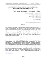
The movement of a single blade into the soil
is schematically shown in Figure 9. This
figure explains that the blade started to enter
into the soil profile at an angle of 23.54˚ and
exits at an angle of 94.70˚, respectively for 16
cm radius of the rotor set at 9.6 cm depth of
Fuel consumption
The fuel consumption was found to be
decreased as with the moisture content as
shown in Figure 7. The possible reason might
be the reduced soil strength which allows
291
Int.J.Curr.Microbiol.App.Sci (2019) 8(2): 287-299
operation. When two consecutive blades of
thesame flange cut the soil then a prismatic
shape of soil wedge is formedas shown in
figure 10. The geometry of cut soil mass
majorly depends on the depth of cut, the
speed of forward travel and speed of the rotor.
of blade and torque required to cut the soil is
represented in figure 11. It reflects that the
torque required to cut the soil slice increases
with the angle of rotation of the blade.
Initially, at a blade angle of 23.54˚, the cutting
force was found to be minimal and it
increases till the exit point (94.70˚ blade
angle). This could be due to the increase in
the depth of penetration of the blade with the
angle of rotation.
In this figure, Lb, Wc, dc, and Ltr represents the
bite-length, width of cut, depth of cut and
length of tilling route respectively. The
relationship between of angle of penetration
Table.1 Tree spacing, canopy diameter, pruning height, trunk diameter and season of weeding of
different horticultural crops
Name of crop
Tree spacing,
mxm
Apple
5×5, 4×4
Canopy
diameter,
m
3.5-4
Pruning
height,
cm
100
Trunk
dia.,
cm
25
Season of weeding
Sweet orange
Orange
Lemon
Kinnow
6×6
6×6
5×5
7×7, 4×4
4-4.2
3-3.5
3.6-4
3-3.85
45
45
45
30
15-20
20-25
15-25
15-25
May–July and early in
spring
–
Repeat in every 120 days
–
–
Guava
Litchi
Mango
Pomegranate
s
Sapota
6×6, 5×5
8×8
12×12,10×10
5×5, 4×4
3-3.5
5.5-6
6-8
2.5-3
60-90
45
75
60- 100
25
15-25
25-40
15-20
Rainy season
Repeat in every 2 months
Pre and post monsoon
–
10×10
3-4
100
25-40
–
Source: National Horticultural Board, Ministry of Agriculture and Farmers welfare, Govt. of India
Table.2 List of explanatory variables, their notation, unit and operating levels
S. no.
1
2
3
Name of variable
Type of soil cutting blade
Moisture content of soil
Kinematic parameter (λ-ratio)
Notation
B
M
λ
Unit
%
-
J
10.00
8.86
Level
L
12.40 14.95
7.01
5.60
Table.3 List of response variables, their notation and unit
S. no.
1
2
3
Name of variable
Mean weight diameter of soil
Weeding efficiency
Fuel consumption
Notation
DMM
ηw
FC
292
Unit
mm
%
l/h
16.40
4.80
Int.J.Curr.Microbiol.App.Sci (2019) 8(2): 287-299
Table.4 Mean weight diameter, weeding efficiency and fuel consumption for the side –shift
offset rotavator at the different blade, soil moisture content and kinematic parameter (λ– ratio)
No. of
experiment
s
1
2
3
4
5
6
7
8
9
10
11
12
13
14
15
16
17
18
19
20
21
22
23
24
25
26
27
28
29
30
31
32
Explanatory parameters
Shape
Moisture
λ–
of blade content, % ratio
B2
B1
B1
B1
B1
B2
B2
B2
B2
B1
B2
B2
B1
B1
B1
B1
B1
B1
B2
B2
B2
B2
B2
B2
B2
B1
B1
B1
B1
B2
B1
B2
M3
M3
M1
M4
M1
M4
M1
M4
M4
M4
M2
M3
M2
M3
M3
M2
M1
M4
M2
M3
M2
M3
M1
M1
M2
M2
M4
M2
M1
M4
M3
M1
4
3
3
1
2
3
3
1
4
2
3
3
3
4
2
4
1
4
4
2
2
1
1
2
1
1
3
2
4
2
1
4
Response parameters
Mean
Weeding
Fuel
weightdiamet efficiency, % consumption, l/h
er, mm
1.207
100.0
3.32
1.293
100.0
3.14
0.413
100.0
3.26
0.836
100.0
2.49
0.271
91.66
3.14
1.266
100.0
3.19
0.308
100.0
3.38
0.777
88.88
3.00
1.533
85.71
3.30
0.837
85.71
2.66
0.316
100.0
3.27
0.879
90.00
3.26
0.481
87.50
3.18
1.701
75.00
3.23
1.031
100.0
2.93
0.669
88.88
3.23
0.261
100.0
3.09
2.087
100.0
3.06
0.455
83.33
3.41
0.616
100.0
3.15
0.264
100.0
3.21
0.556
100.0
3.08
0.225
100.0
3.12
0.231
100.0
3.20
0.239
100.0
3.13
0.280
100.0
2.98
1.600
100.0
2.78
0.336
100.0
3.11
0.722
84.61
3.31
0.829
75.00
3.06
0.794
100.0
2.81
0.359
75.00
3.45
293
Int.J.Curr.Microbiol.App.Sci (2019) 8(2): 287-299
Fig.1 Illustration of the working of side-shift offset rotavator
Fig.2 An operational view of the side-shift offset rotavator
Fig.3 Motorized sieve shaker used for sieving the pulverized soil sample
294
Int.J.Curr.Microbiol.App.Sci (2019) 8(2): 287-299
Fig.4 Attachment of fuel meter between the fuel line and engine of the tractor
Fig.5 Variation in mean weight diameter of the soil with moisture content
Fig.6 Variation in Mean weight diameter of the soil with kinematic parameter (λ–ratio)
295
Int.J.Curr.Microbiol.App.Sci (2019) 8(2): 287-299
Fig.7 Variation in fuel consumption with a moisture content of the soil
Fig.8 Variation in fuel consumption with kinematic parameter (λ–ratio)
Fig.9 A typical schematic view of the movement of a single blade into the soil
296
Int.J.Curr.Microbiol.App.Sci (2019) 8(2): 287-299
Fig.10 Schematic view of the soil slice cut by the rotor blade
Fig.11 Torque required by the leg of the blade to cut the soil slice
Fig.12 Torque required by the leg of the blade to overcome frictional forces
297
Int.J.Curr.Microbiol.App.Sci (2019) 8(2): 287-299
Fig.13 Torque required by the span of the cutting blade to throw the cut soil slice
The active earth pressure increases with the
depth and makes the soil more compacted
which increases its strength. That is why, in
order to make a deeper cut into the soil, the
blade requires higher force. The peak of this
torque was predicted at the maximum depth
of cut (9.6 cm). At this position, the blade
shows the highest magnitude of force/torque
required to cut the soil for the maximum set
tillage depth. The sudden drop of force
requirement becomes zero because beyond
this angle the blade moves in the soil mass
which was already cultivated. The strength of
pulverized soil is negligible which offers
almost zero resistance to cut.
The force required to throw the cut soil mass
was found to be reduced with the angle of
rotation of the blade. Initially, it was
maximum at the entrance (23.54˚) because at
this point the thickness of soil slice was
maximum (Fig. 13) therefore the mass of soil.
It reduces beyond this angle and found to be
minimum at the exit point of the blade
(94.70˚). The reason behind that was the
reduced thickness of soil slice (Fig. 13) and
hence the mass. Therefore, the lower amount
of force required to throw the reduced mass of
soil.
The mean weight diameter of soil for the side
–shift offset rotavator equipped with L shape
blade was about 50% higher than J shape
blade at 10% soil moisture (Table 3). This
difference was reduced up to 20% at 16.40%
soil moisture. The MWD of soil was lower
about 23% for L shape blade as compared to J
shape blade at 8.86 λ-ratio. This difference
was increased by 46% at 4.80 λ-ratio. The
difference in fuel consumption was negligible
for both the blades at the initial level of soil
moisture, but it was found about 15% higher
in L shape blade at 16.40% soil moisture.
While considering the λ-ratio, it was
concluded that the difference in fuel
consumption was not much substantial at its
The torque required to overcome the frictional
forces is depicted in Figure 12. The blade
moves in the soil produce some parasitic
forces. During its motion, it has to overcome
from soil-soil, soil-metal frictional forces.
These forces highly depend on the soil type,
soil moisture content, and tool’s surface
roughness and contact area. As the
penetration increases the contact area also
increases and therefore the frictional forces
also increase. It attains the maximum value at
its maximum depth of operation and then
sudden decreases because of friction applied
by loose soils.
298
Int.J.Curr.Microbiol.App.Sci (2019) 8(2): 287-299
distinct levels.
Marenya, M.O. du Plessis H.L.M. and
Musonda N.G. 2003. Theoretical force
and power 10 prediction models for
rotary tillers – a review. Journal of
Engineering in Agriculture and 11 the
Environment, 3(1): 1–10.
National Horticultural Board, 2017. Ministry
of Agriculture and Farmers welfare,
Govt. of India.
Shekhar Kumar Sahu, Kunj Bihari Tiwari,
Prateek Shrivastava and Rohit Namdeo.
2018. Optimization of the Kinematic
Parameter and Fuel Consumption for
the Side-Shift Offset Rotavator Using L
and J–Shape Soil Cutting Blades.
Int.J.Curr.Microbiol.App.Sci.
7(08):
1970-1982.
References
Kemper, W.D. and Rosenau, R.C., 1986.
Aggregate
stability
and
size
distribution.
Marenya, M. O. 2009. Performance
characteristics of a deep tilling
rotavator. Unpublished Ph. D. thesis.
Department of Civil and Biosystems
Engineering, University of Pretoria.
Pretoria, South Africa.
Marenya, M. O. and du Plessis H. L. M.,
2006. Torque requirements and forces
generated by a deep tilling down-cut
rotary tiller. ASAE Paper No. 061096.
St. Joseph, Mich.: ASABE.
How to cite this article:
Shekhar Kumar Sahu and Kunj Bihari Tiwari. 2019. Assessment of the Performance
Parameters forthe Side-Shift Offset Rotavator. Int.J.Curr.Microbiol.App.Sci. 8(02): 287-299.
doi: />
299