(Bosch professional automotive information) Gasoline Engine Management Systems and Component 2015
Bạn đang xem bản rút gọn của tài liệu. Xem và tải ngay bản đầy đủ của tài liệu tại đây (11.85 MB, 363 trang )
Bosch Professional Automotive
Information
Konrad Reif Ed.
Gasoline Engine
Management
Systems and Components
Bosch Professional Automotive Information
Bosch Professional Automotive Information is a definitive reference for
automotive engineers. The series is compiled by one of the world´s largest
automotive equipment suppliers. All topics are covered in a concise but
descriptive way backed up by diagrams, graphs, photographs and tables
enabling the reader to better comprehend the subject.
There is now greater detail on electronics and their application in the motor
vehicle, including electrical energy management (EEM) and discusses the
topic of intersystem networking within vehicle. The series will benefit
automotive engineers and design engineers, automotive technicians in
training and mechanics and technicians in garages.
Konrad Reif
Editor
Gasoline Engine
Management
Systems and Components
Editor
Prof. Dr.-Ing. Konrad Reif
Duale Hochschule Baden-Württemberg
Friedrichshafen, Germany
ISBN 978-3-658-03963-9
DOI 10.1007/978-3-658-03964 -6
ISBN 978-3-658-03964 -6 (eBook)
Library of Congress Control Number: 2014945106
Springer Vieweg
© Springer Fachmedien Wiesbaden 2015
This work is subject to copyright. All rights are reserved, whether the whole or part of the material is
concerned, specifically the rights of translation, reprinting, reuse of illustrations, recitation, broadcasting,
reproduction on microfilm or in any other way, and storage in data banks. Duplication of this publication
or parts thereof is permitted only under the provisions of the German Copyright Law of September 9, 1965,
in its current version, and permission for use must always be obtained from Springer. Violations are liable
to prosecution under the German Copyright Law.
The use of general descriptive names, registered names, trademarks, etc. in this publication does not imply,
even in the absence of a specific statement, that such names are exempt from the relevant protective laws
and regulations and therefore free for general use.
Printed on acid-free paper.
Springer is part of Springer Science+Business Media
www.springer.com
Foreword
▶
Foreword
The call for environmentally compatible and economical vehicles necessitates immense efforts to develop innovative engine concepts. Technical concepts such as gasoline direct injection helped to save fuel up to 20 % and reduce CO2-emissions.
Descriptions of the cylinder-charge control, fuel injection, ignition and catalytic
emission-control systems provides comprehensive overview of today´s gasoline engines. This book also describes emission-control systems and explains the diagnostic
systems. The publication provides information on engine-management-systems and
emission-control regulations.
Complex technology of modern motor vehicles and increasing functions need a reliable source of information to understand the components or systems. The rapid and
secure access to these informations in the field of Automotive Electrics and Electronics provides the book in the series “Bosch Professional Automotive Information”
which contains necessary fundamentals, data and explanations clearly, systematically, currently and application-oriented. The series is intended for automotive professionals in practice and study which need to understand issues in their area of work.
It provides simultaneously the theoretical tools for understanding as well as the
applications.
V
VI
Contents
▶
Contents
2 History of the automobile
101 Mixture formation
2 Development history
105 Ignition of homogeneous air/fuel mixtures
4 Pioneers of automotive technology
106 Electromagnetic fuel injectors
6 Robert Bosch’s life’s work (1861–1942)
110 Gasoline direct injection
8 Basics of the gasoline (SI) engine
110 Overview
8 Method of operation
110 Method of operation
12 Cylinder charge
111 Combustion process
16 Torque and power
114 Operating modes
18 Engine efficiency
117 Mixture formation
20 Specific fuel consumption
119 Ignition
22 Combustion knock
120 High-pressure injector
24 Fuels
122 Operation of gasoline engines on
24 Fuels for spark-ignition engines (gasolines)
29 Alternative fuels
natural gas
122 Overview
124 Design and method of operation
32 Cylinder-charge control systems
125 Mixture formation
32 Electronic throttle control (ETC)
127 Natural-gas injector NGI2
36 Variable valve timing
130 Natural-gas rail
39 Dynamic supercharging
130 Combined natural-gas pressure and
42 Mechanical supercharging
temperature sensor
44 Exhaust-gas turbocharging
131 DS-HD-KV4 high-pressure sensor
47 Intercooling
132 TV-NG1 tank shutoff valve
48 Controlled charge flow
133 PR-NG1 pressure-regulator module
49 Exhaust-gas recirculation (EGR)
136 Ignition systems over the years
50 Gasoline injection systems over the years
136 Overview
50 Overview
138 Early ignition evolution
52 Beginnings of mixture formation
146 Battery ignition systems over the years
60 Evolution of gasoline injection systems
152 Inductive ignition system
76 Fuel supply
152 Design
76 Fuel delivery with manifold injection
153 Function and method of operation
78 Fuel delivery with gasoline direct injection
155 Ignition parameters
79 Evaporative-emissions control system
159 Voltage distribution
80 Electric fuel pump
160 Ignition driver stage
83 Gasoline filter
161 Connecting devices and interference
85 High-pressure pumps for gasoline
suppressors
direct injection
92 Fuel rail
162 Ignition coils
93 Pressure-control valve
162 Function
94 Fuel-pressure regulator
163 Requirements
95 Fuel-pressure damper
164 Design and method of operation
170 Types
96 Manifold injection
174 Ignition-coil electronics
96 Overview
175 Electrical parameters
97 Method of operation
177 Simulation-based development of
100 Instants of injection
ignition coils
Contents
178 Spark plugs
268 Catalytic emission control
178 Function
268 Overview
179 Usage
269 Three-way catalytic converter
180 Requirements
272 NOX accumulator-type catalytic converter
181 Design
274 Catalytic-converter configurations
184 Electrode materials
276 Catalytic-converter heating
185 Spark-plug concepts
280 Lambda control loop
186 Electrode gap
187 Spark position
284 Emission-control legislation
188 Spark-plug heat range
284 Overview
190 Adaptation of spark plugs
286 CARB legislation (passenger cars/LDTs)
194 Spark-plug performance
289 EPA legislation (passenger cars/LDTs)
196 Types
291 EU legislation (passenger cars/LDTs)
203 Spark-plug type designations
294 Japanese legislation (passenger cars/LDTs)
204 Manufacture of spark plugs
294 US test cycles for passenger cars
206 Simulation-based spark-plug development
and LDTs
207 Handling spark plugs
296 European test cycle for passenger cars and
212 Electronic Control
297 Japanese test cycle for passenger cars and
LDTs
212 Open- and closed-loop electronic control
LDTs
218 Motronic versions
224 System structure
298 Exhaust-gas measuring techniques
226 Subsystems and main functions
298 Exhaust-gas test for type approval
300 Exhaust-gas analyzers
234 Sensors
303 Evaporative-emissions test
234 Automotive applications
235 Temperature sensors
304 Diagnosis
236 Engine-speed sensors
304 Monitoring during vehicle operation
238 Hall-effect phase sensors
240 Hot-film air-mass meter
243 Piezoelectric knock sensors
244 Micromechanical pressure sensors
(on-board diagnosis)
307 On-board-diagnosis system for passenger
cars and light-duty trucks
324 Diagnosis in the workshop
246 High-pressure sensors
248 Two-step lambda oxygen sensors
326 ECU development
252 LSU4 planar broad-band lambda
326 Hardware development
oxygen sensor
330 Function development
332 Software development
254 Electronic control unit (ECU)
336 Application-related adaptation
254 Operating conditions
343 Quality management
254 Design
254 Data processing
260 Exhaust emissions
260 Combustion of the air/fuel mixture
261 Main constituents of exhaust gas
262 Pollutants
264 Factors affecting untreated emissions
VII
VIII
Authors
▶
Authors
History of the automobile
Dr. rer. nat. Winfried Langer,
Dipl.-Ing. Karl-Heinz Dietsche,
Dr.-Ing. habil. Jürgen Förster,
Dietrich Kuhlgatz.
Dr.-Ing. Jens Thurso,
Jürgen Wörsinger.
Basics of the gasoline (SI) engine
Dr. rer. nat. Dirk Hofmann,
Ignition systems over the years
Dipl.-Ing. Bernhard Mencher,
Dipl.-Ing. Karl-Heinz Dietsche.
Dipl.-Ing. Werner Häming,
Dipl.-Ing. Werner Hess.
Inductive ignition system
Dipl.-Ing. Walter Gollin.
Fuels
Dr. rer. nat. Jörg Ullmann,
Ignition coils
Dipl.-Ing. (FH) Thorsten Allgeier.
Dipl.-Ing. (FH) Klaus Lerchenmüller,
Dipl.-Ing. (FH) Markus Weimert,
Cylinder-charge control systems
Dipl.-Ing. Tim Skowronek.
Dr. rer. nat. Heinz Fuchs,
Dipl.-Ing. (FH) Bernhard Bauer,
Spark plugs
Dipl.-Phys. Torsten Schulz,
Dipl.-Ing. Erich Breuser.
Dipl.-Ing. Michael Bäuerle,
Dipl.-Ing. Kristina Milos.
Electronic Control
Dipl.-Ing. Bernhard Mencher,
Gasoline injection systems over the years
Dipl.-Ing. (FH) Thorsten Allgeier,
Dipl.-Ing. Karl-Heinz Dietsche.
Dipl.-Ing. (FH) Klaus Joos,
Dipl.-Ing. (BA) Andreas Blumenstock,
Fuel supply
Dipl.-Red. Ulrich Michelt.
Dipl.-Ing. Jens Wolber,
Ing. grad. Peter Schelhas,
Sensors
Dipl.-Ing. Uwe Müller,
Dr.-Ing. Wolfgang-Michael Müller,
Dipl.-Ing. (FH) Andreas Baumann,
Dr.-Ing. Uwe Konzelmann,
Dipl.-Betriebsw. Meike Keller.
Dipl.-Ing. Roger Frehoff,
Dipl.-Ing. Martin Mast,
Manifold injection
Dr.-Ing. Johann Riegel.
Dipl.-Ing. Anja Melsheimer,
Dipl.-Ing. Rainer Ecker,
Electronic control unit (ECU)
Dipl.-Ing. Ferdinand Reiter,
Dipl.-Ing. Martin Kaiser.
Dipl.-Ing. Markus Gesk.
Exhaust emissions
Gasoline direct injection
Dipl.-Ing. Christian Köhler,
Dipl.-Ing. Andreas Binder,
Dipl.-Ing. (FH) Thorsten Allgeier.
Dipl.-Ing. Rainer Ecker,
Dipl.-Ing. Andreas Glaser,
Catalytic emission control
Dr.-Ing. Klaus Müller.
Dr.-Ing. Jörg Frauhammer,
Dr. rer. nat. Alexander Schenck zu Schweinsberg,
Operation of gasoline engines on natural gas
Dipl.-Ing. Klaus Winkler.
Dipl.-Ing. (FH) Thorsten Allgeier,
Dipl.-Ing. (FH) Martin Haug,
Emission-control legislation
Dipl.-Ing. Roger Frehoff,
Dipl.-Ing. Bernd Kesch,
Dipl.-Ing. Michael Weikert,
Dipl.-Ing Ramon Amirpour,
Dipl.-Ing. (FH) Kai Kröger,
Dr. Michael Eggers.
Authors
Exhaust-gas measuring techniques
Dipl.-Phys. Martin-Andreas Drühe.
Diagnosis
Dr.-Ing. Matthias Knirsch,
Dipl.-Ing. Bernd Kesch,
Dr.-Ing. Matthias Tappe,
Dr.-Ing. Günter Driedger,
Dr. rer. nat. Walter Lehle.
ECU development
Dipl.-Ing. Martin Kaiser,
Dipl.-Phys. Lutz Reuschenbach,
Dipl.-Ing. (FH) Bert Scheible,
Dipl.-Ing. Eberhard Frech.
and the editorial team in cooperation with the
responsible in-house specialist departments.
IX
2
History of the automobile
Development history
History of the automobile
Mobility has always played a crucial role in
the course of human development. In almost every era, man has attempted to find
the means to allow him to transport people
over long distances at the highest possible
speed. It took the development of reliable
internal-combustion engines that were operated on liquid fuels to turn the vision of
a self-propelling “automobile” into reality
(combination of Greek: autos = self and
Latin: mobilis = mobile).
Daimler Motorized
Carriage, 1894
(Source:
DaimlerChrysler Classic,
Corporate Archives)
The first journey with an
engine-powered vehicle
is attributed to Joseph
Cugnot (in 1770).
His lumbering, steampowered, wooden
three-wheeled vehicle
was able to travel for
all of 12 minutes on a
single tankful of water.
The patent issued to Benz
on January 29, 1886 was
not based on a converted
carriage. Instead, it was a
totally new, independent
construction
(Source:
DaimlerChrysler Classic,
Corporate Archives)
Development history
It would be hard to imagine life in our modern day without the motor car. Its emergence
required the existence of many conditions
without which an undertaking of this kind
would not have been possible. At this point,
some development landmarks may be worthy
of note. They represent an essential contribution to the development of the automobile:
¼ About 3500 B.C.
The development of the wheel is attributed to the Sumerians
¼ About 1300
Further refinement of the carriage with
elements such as steering, wheel suspension and carriage springs
¼ 1770
Steam buggy by Joseph Cugnot
¼ 1801
Étienne Lenoir develops the gas engine
¼ 1870
Nikolaus Otto builds the first four-stroke
internal-combustion engine
In 1885 Carl
Benz enters the
annals of history as the inventor of the
first automobile. His patent
marks the beginning of the
rapid development of the
automobile
powered by the internal-combustion engine.
Public opinion remained divided, however.
While the proponents of the new age lauded
the automobile as the epitome of progress,
the majority of the population protested
against the increasing annoyances of dust,
noise, accident hazard, and inconsiderate
motorists. Despite all of this, the progress
of the automobile proved unstoppable.
In the beginning, the acquisition of an automobile represented a serious
challenge.
A road network
was virtually nonexistent; repair shops were
unknown, fuel was purchased at the drugstore,
and spare parts were produced on demand by
the local blacksmith. The prevailing circumstances made the first long-distance journey by
Bertha Benz in 1888 an even more astonishing
accomplishment. She is thought to have been
the first woman behind the wheel of a motorized vehicle. She also demonstrated the reliability of the automobile by journeying the then
enormous distance of more than 100 kilometers (about 60 miles) between Mannheim and
Pforzheim in south-western Germany.
In the early days, however, few entrepreneurs
– with the exception of Benz – considered
the significance of the engine-powered vehicle on a worldwide scale. It was the French
who were to help the automobile to greatness. Panhard & Levassor used licenses for
Daimler engines to build their own automobiles. Panhard pioneered construction features such as the steering wheel, inclined
steering column, clutch pedal, pneumatic
tires, and tube-type radiator.
In the years that followed, the industry
mushroomed with the arrival of companies
such as Peugeot, Citroën, Renault, Fiat, Ford,
Rolls-Royce, Austin, and others. The influence of Gottlieb Daimler, who was selling
his engines almost all over the world, added
significant impetus to these developments.
K. Reif (Ed.), Gasoline Engine Management, Bosch Professional Automotive Information,
DOI 10.1007/978-3-658-03964-6_1, © Springer Fachmedien Wiesbaden 2015
History of the Automobile
Taking their original design from coachbuilding, the motor cars of the time would soon
evolve into the automobiles as we know them
today. However, it should be noted that each
automobile was an individual product of
purely manual labor. A fundamental change
came with the introduction of the assembly
line by Henry Ford in 1913. With the Model T,
he revolutionized the automobile industry in
the United States. It was exactly at this juncture that the automobile ceased to be an article of luxury. By producing large numbers
of automobiles, the price of an automobile
dropped to such a level that it became accessible to the general public for the first time.
Although Citroën and Opel were among the
first to bring
the assembly
line to Europe,
it would gain
acceptance only
in the mid1920s.
Automobile manufacturers were quick to realize that, in order to be successful in the marketplace, they had to accommodate the wishes of
their customers. Automobile racing victories
were exploited for commercial advertising.
With ever-advancing speed records, professional race drivers left indelible impressions of
themselves and the brand names of their automobiles in the minds of spectators. In addition,
efforts were made to broaden the product line.
As a result, the following decades produced a
variety of automobile designs based on the prevailing zeitgeist, as well as the economic and
political influences of the day. E.g., streamlined
vehicles were unable to gain acceptance prior to
WWII due to the demand for large and representative automobiles. Manufacturers of the
time designed and built the most exclusive automobiles, such
as the Mercedes-Benz 500 K,
Rolls-Royce
Phantom III,
Horch 855, or
Bugatti Royale.
Development history
WWII had a significant influence
on the development of smaller
cars. The Volkswagen model
that came to be
known as the
“Beetle” was designed by Ferdinand Porsche
and was manufactured in Wolfsburg. At the
end of the war, the demand for cars that were
small and affordable was prevalent. Responding to this demand, manufacturers produced
automobiles such as the Goliath GP 700,
Lloyd 300, Citroën 2CV, Trabant, Isetta, and
the Fiat 500 C (Italian name: Topolino = little
mouse). The manufacture of automobiles began to evolve new standards; there was greater
emphasis on technology and integrated accessories, with a reasonable price/performance
ratio as a major consideration.
Today, the emphasis is on a
high level of
occupant
safety; the everrising traffic
volumes and
significantly
higher speeds compared with yesteryear are
making the airbag, ABS, TCS, ESP, and intelligent sensors virtually indispensable. The
ongoing development of the automobile has
been powered by innovative engineering on
the part of the auto industry and by the constant rise in market demands. However,
there are fields of endeavor that continue
to present a challenge well into the future.
One example is the further reduction of
environmental burdens through the use of
alternative energy sources (e.g., fuel cells).
One thing, however, is not expected to
change in the near future – it is the one concept that has been associated with the automobile for more than a century, and which
had inspired its original creators – it is the
enduring ideal of individual mobility.
3
More than 15 million
units were produced of
the Model T, affectionately called “Tin Lizzie”.
This record would be
topped only by the
Volkswagen Beetle
in the 1970s
(Photos: Ford,
Volkswagen AG)
Contemporary studies
indicate what automobiles of tomorrow
might look like
(Photo: Peugeot)
In 1899 the Belgian
Camille Jenatzy was the
first human to break the
100 km/h barrier. Today,
the speed record stands
at 1227.9 km/h.
Mercedes-Benz 500 K
Convertible C, 1934
(Source:
DaimlerChrysler Classic,
Corporate Archives)
4
History of the Automobile
Pioneers of automotive technology
Pioneers of automotive
technology
Owing to the large
number of people who
contributed to the development of the automobile, this list makes no
claim to completeness
1866: Nikolaus August
Otto (Photo: Deutz AG)
acquires the patent for
the atmospheric gas
machine
Wilhelm Maybach
(Photo: MTU
Friedrichshafen GmbH)
Nikolaus August
Otto (1832–1891),
born in Holzhausen
(Germany), developed an interest in
technical matters at
an early age. Beside
his employment as
a traveling salesman
for food wholesalers,
he was preoccupied with the functioning of
gas-powered engines.
From 1862 onward he dedicated himself
totally to engine construction. He managed
to make improvements to the gas engine
invented by the French engineer, Étienne
Lenoir. For this work, Otto was awarded the
gold medal at the 1867 Paris World Fair.
Together with Daimler and Maybach, he
developed an internal-combustion engine
based on the four-stroke principle he had
formulated in 1861. The resulting engine is
known as the “Otto engine” to this day. In
1884 Otto invented magneto ignition, which
allowed engines to be powered by gasoline.
This innovation would form the basis for
the main part of Robert Bosch’s life’s work.
Otto’s singular contribution was his ability
to be the first to build the four-stroke internal-combustion engine and demonstrate its
superiority over all its predecessors.
Gottlieb Daimler
(Photo:
DaimlerChrysler Classic,
Corporate Archives)
Gottlieb Daimler
(1834–1900) hailed
from Schorndorf
(Germany). He
studied mechanical
engineering at the
Polytechnikum engineering college in
Stuttgart. In 1865
he met the highly
talented engineer Wilhelm Maybach. From
that moment on, the two men would be
joined in a lasting relationship of mutual
cooperation. Besides inventing the first motorcycle, Daimler mainly worked on developing a gasoline engine suitable for use in road
vehicles. In 1889 Daimler and Maybach introduced the first “steel-wheeled vehicle”
in Paris featuring a two-cylinder V-engine.
Scarcely one year later, Daimler was marketing his fast-running Daimler engine on an
international scale. In 1891, for example,
Armand Peugeot successfully entered a vehicle he had engineered himself in the ParisBrest-Paris long-distance trial. It proved both
the worth of his design and the dependability
of the Daimler engine he was using.
Daimler’s merits lie in the systematic development of the gasoline engine and in the
international distribution of his engines.
Wilhelm Maybach
(1846–1929), a native of Heilbronn
(Germany), completed his apprenticeship as a technical draftsman. Soon
after, he worked as
a design engineer.
Among his employers was the firm of Gasmotoren Deutz AG
(founded by Otto). He already earned the
nickname of “king of engineers” during his
own lifetime.
Maybach revised the gasoline engine and
brought it to production. He also developed
water cooling, the carburetor, and the dualignition system. In 1900 Maybach built a
revolutionary, alloy-based racing car. This
vehicle was developed in response to a suggestion by an Austrian businessman named
Jellinek. His order for 36 of these cars was
given on condition that the model was to be
named after his daughter Mercedes.
Maybach’s virtuosity as a design engineer
pointed the way to the future of the contemporary automobile industry. His death signaled the end of the grand age of the automotive pioneers.
History of the Automobile
Carl Friedrich Benz
(1844–1929), born
in Karlsruhe (Germany), studied mechanical engineering
at the Polytechnikum engineering
college in his hometown. In 1871 he
founded his first
company, a factory for iron-foundry
products and industrial components in
Mannheim.
Independently of Daimler and Maybach,
he also pursued the means of fitting an engine in a vehicle. When the essential claims
stemming from Otto’s four-stroke engine
patent had been declared null and void,
Benz also developed a surface carburetor,
electrical ignition, the clutch, water cooling,
and a gearshift system, besides his own fourstroke engine. In 1886 he applied for his
patent and presented his motor carriage to
the public. In the period until the year 1900,
Benz was able to offer more than 600 models
for sale. In the period between 1894 and
1901 the factory of Benz & Co. produced the
“Velo”, which, with a total output of about
1200 units, may be called the first mass-produced automobile. In 1926 Benz merged
with Daimler to form “Daimler-Benz AG”.
Carl Benz introduced the first automobile
and established the preconditions for the industrial manufacture of production vehicles.
Henry Ford
(1863–1947) hailed
from Dearborn,
Michigan (USA).
Although Ford had
found secure employment as an
engineer with the
Edison Illuminating
Company in 1891,
his personal interests were dedicated to the
advancement of the gasoline engine.
Pioneers of automotive technology
5
In 1893 the Duryea Brothers built the first
American automobile. Ford managed to even
the score in 1896 by introducing his own car,
the “Quadricycle Runabout”, which was to
serve as the basis for numerous additional designs. In 1908 Ford introduced the legendary
“Model T”, which was mass-produced on assembly lines from 1913 onward. Beginning in
1921, with a 55-percent share in the country’s
industrial production, Ford dominated the
domestic automobile market in the USA.
1886: As inventor of the
first automobile fitted with
an internal-combustion
engine, Benz enters the
annals of world history
(Photo:
DaimlerChrysler Classic,
Corporate Archives)
The name Henry Ford is synonymous with
the motorization of the United States. It was
his ideas that made the automobile accessible to a broad segment of the population.
Rudolf Christian
Karl Diesel
(1858–1913), born
in Paris (France),
decided to become
an engineer at the
age of 14. He graduated from the Polytechnikum engineering college in
Munich with the best marks the institution
had given in its entire existence.
In 1892 Diesel was issued the patent for
the “Diesel engine” that was later to bear his
name. The engine was quickly adopted as a
stationary power plant and marine engine.
In 1908 the first commercial truck was powered by a diesel engine. However, its entrance
into the world of passenger cars would take
several decades. The diesel engine became the
power plant for the serial-produced Mercedes
260 D as late as 1936. Today’s diesel engine
has reached a level of development such that
it is now as common as the gasoline engine.
With his invention, Diesel has made a major
contribution to a more economical utilization of the internal-combustion engine. Although Diesel became active internationally
by granting production licenses, he failed to
earn due recognition for his achievements
during his lifetime.
Rudolf C. K. Diesel
(Photo: Historical
Archives of MAN AG)
Henry Ford
(Photo: Ford)
6
History of the Automobile
Robert Bosch’s life’s work
Robert Bosch’s life’s work
(1861–1942)
“It has always been an
unbearable thought to
me that someone could
inspect one of my products and find it inferior
in any way. For that reason, I have constantly
endeavored to make
products that withstand
the closest scrutiny –
products that prove
themselves superior
in every respect.”
Robert Bosch
Robert Bosch, born on September 23, 1861 in
Albeck near Ulm (Germany), was the scion of
a wealthy farmer’s family. After completing his
apprenticeship as a precision fitter, he worked
temporarily for a number of enterprises, where
he continued to hone his technical skills and
expand his merchandising abilities and experience. After six months as an auditor studying
electrical engineering at Stuttgart technical
university, he traveled to the United States to
work for “Edison Illuminating”. He was later
employed by “Siemens Brothers” in England.
(Photos:
Bosch Archives)
First ad in the Stuttgart
daily “Der Beobachter”
(The Observer), 1887
In 1886 he decided to open a “Workshop
for Precision Mechanics and Electrical
Engineering” in the back of a dwelling in
Stuttgart’s west end. He employed another
mechanic and an apprentice. At the beginning, his field of work lay in installing and
repairing telephones, telegraphs, lightning
conductors, and other light-engineering
jobs. His dedication in finding rapid solutions to new problems also helped him gain
a competitive lead in his later activities.
To the automobile industry, the low-voltage
magneto ignition developed by Bosch in 1897
represented – much unlike its unreliable predecessors – a true breakthrough. This product
was the launching board for the rapid expansion of Robert Bosch’s business. He always
managed to bring the purposefulness of the
world of technology and economics into harmony with the needs of humanity. Bosch was
a trailblazer in many aspects of social care.
Robert Bosch performed technological pioneering work in developing and bringing the
following products to maturity:
¼ Low-voltage magneto ignition
¼ High-voltage magneto ignition for higher
engine speeds (engineered by his colleague
Gottlob Honold)
¼ Spark plug
¼ Ignition distributor
¼ Battery (passenger vehicles and motorcycles)
¼ Electrical starter
¼ Generator (alternator)
¼ Lighting system with first electric headlamp
¼ Diesel injection pumps
¼ Car radio (manufactured by “Ideal-Werke”,
renamed “Blaupunkt” in 1938)
¼ First lighting system for bicycles
¼ Bosch horn
¼ Battery ignition
¼ Bosch semaphore turn signal (initially
ridiculed as being typical of German sense
of organization – now the indispensable
direction indicator)
At this point, many other achievements,
also in the area of social engagement, would
be worthy of note. They are clear indicators
that Bosch was truly ahead of his time. His
forward-thinking mind has given great impetus to advances in automobile development. The rising number of self-driving motorists fostered a corresponding increase in
the need for repair facilities. In the 1920s
Robert Bosch launched a campaign aimed
History of the Automobile
Robert Bosch’s life’s work
at creating a comprehensive service organization. In 1926, within Germany, these service repair centers were uniformly named
“Bosch-Dienst” (Bosch Service) and the
name was registered as a trademark.
Bosch had similarly high ambitions with
regard to the implementation of social-care
objectives. Having introduced the 8-hour day
in 1906, he compensated his workers with
ample wages. In 1910 he donated one million
reichsmarks to support technical education.
Bosch took the production of the 500,000th
magneto as an occasion to introduce the
work-free Saturday afternoon. Among other
Bosch-induced improvements were old-age
pensions, workplaces for the severely handicapped, and the vacation scheme. In 1913 the
Bosch credo, “Occupation and the practice of
apprenticeship are more knowledgeable educators than mere theory” resulted in the inauguration of an apprentice workshop that
provided ample space for 104 apprentices.
In mid-1914 the name of Bosch was already
represented around the world. But the era
of great expansion between 1908 and 1940
would also bring the strictures of two world
wars. Prior to 1914, 88 % of the products
made in Stuttgart were slated for export.
Bosch was able to continue expansion with
the aid of large contingents destined for the
military. However, in light of the atrocities of
the war years, he disapproved of the resulting
profits. As a result, he donated 13 million
reichsmarks for social-care purposes.
After the end of WWI it was difficult to regain
a foothold in foreign markets. In the United
States, for example, Bosch factories, sales offices, and the corporate logo and symbol had
been confiscated and sold to an American
company. One of the consequences was that
products appeared under the “Bosch” brand
name that were not truly Bosch-made. It
would take until the end of the 1920s before
Bosch had reclaimed all of his former rights
and was able to reestablish himself in the
United States. The Founder’s unyielding de-
7
First offices in London’s
Store Street (Photo:
Bosch Archives)
termination to overcome any and all obstacles
returned the company to the markets of the
world and, at the same time, imbued the
minds of Bosch employees with the international significance of Bosch as an enterprise.
A closer look at two specific events may
serve to underscore the social engagement
of Robert Bosch. In 1936 he donated funds
to construct a hospital that was officially
opened in 1940. In his inaugural speech,
Robert Bosch emphasized his personal dedication in terms of social engagement: “Every
job is important, even the lowliest. Let no
man delude himself that his work is more
important than that of a colleague.”
With the passing of Robert Bosch in 1942,
the world mourned an entrepreneur who
was a pioneer not only in the arena of technology and electrical engineering, but also
in the realm of social engagement. Until this
day, Robert Bosch stands as an example of
progressive zeitgeist, of untiring diligence,
of social improvements, of entrepreneurial
spirit, and as a dedicated champion of education. His vision of progress culminated in
the words, “Knowledge, ability, and will are
important, but success only comes from
their harmonious interaction.”
In 1964 the Robert Bosch Foundation was
inaugurated. Its activities include the promotion and support of health care, welfare,
education, as well as sponsoring the arts and
culture, humanities and social sciences.
The Foundation continues to nurture the
founder’s ideals to this day.
“To each his own
automobile”
Such was the Bosch
claim in a 1931 issue of
the Bosch employee
magazine “BoschZünder” (Bosch Ignitor).
8
Basics of the gasoline (SI) engine
Method of operation
Basics of the gasoline (SI) engine
The gasoline or spark-ignition (SI) internalcombustion engine uses the Otto cycle 1)
and externally supplied ignition. It burns an
air/fuel mixture and in the process converts
the chemical energy in the fuel into kinetic
energy.
For many years, the carburetor was responsible for providing an air/fuel mixture in the
intake manifold which was then drawn into
the cylinder by the downgoing piston.
The breakthrough of gasoline fuel injection, which permits extremely precise metering of the fuel, was the result of the legislation governing exhaust-gas emission limits.
Similar to the carburetor process, with manifold fuel injection the air/fuel mixture is
formed in the intake manifold.
Even more advantages resulted from the
development of gasoline direct injection, in
particular with regard to fuel economy and
increases in power output. Direct injection
injects the fuel directly into the engine cylinder at exactly the right instant in time.
1)
1
2
3
4
5
6
7
8
9
10
11
M
α
s
Vh
Vc
Exhaust camshaft
Spark plug
Intake camshaft
Injector
Intake valve
Exhaust valve
Combustion
chamber
Piston
Cylinder
Conrod
Crankshaft
Torque
Crankshaft angle
Piston stroke
Piston displacement
Compression
volume
The combustion of the air/fuel mixture
causes the piston (Fig. 1, Pos. 8) to perform
a reciprocating movement in the cylinder (9).
The name reciprocating-piston engine, or
better still reciprocating engine, stems from
this principle of functioning.
The conrod (10) converts the piston’s
reciprocating movement into a crankshaft
(11) rotational movement which is maintained by a flywheel at the end of the crankshaft. Crankshaft speed is also referred to as
engine speed or engine rpm.
Four-stroke principle
Today, the majority of the internal-combustion engines used as vehicle power plants are
of the four-stroke type. The four-stroke principle employs gas-exchange valves (5 and 6)
to control the exhaust-and-refill cycle. These
valves open and close the cylinder’s intake
and exhaust passages, and in the process control the supply of fresh air/fuel mixture and
the forcing out of the burnt exhaust gases.
Named after Nikolaus Otto (1832–1891) who presented
the first gas engine with compression using the 4-stroke
principle at the Paris World Fair in 1878.
1
1
2
3
Complete working cycle of the 4-stroke spark-ignition (SI) gasoline engine (example shows a manifold-injection
engine with separate intake and exhaust camshafts)
a
b
c
d
4
5
TDC
Vc
6
7
s
Vh
BDC
8
9
10
11
α
M
K. Reif (Ed.), Gasoline Engine Management, Bosch Professional Automotive Information,
DOI 10.1007/978-3-658-03964-6_2, © Springer Fachmedien Wiesbaden 2015
æ UMM0011-1E
Fig. 1
a Induction stroke
b Compression stroke
c Power (combustion)
stroke
d Exhaust stroke
Method of operation
Basics of the gasoline (SI) engine
Valve timing diagram for a four-stroke
gasoline-engine
0° 5…20°
0…4
15°
10…
ITDC
IT
IO
EC
I E
EO
IC
40…6
0°
BDC
60°
45…
æ UMM0445-1E
on
TDCO
st
au
exh
4th stroke: Exhaust
The exhaust valve (6) opens shortly before
Bottom Dead Center (BDC). The hot (exhaust) gases are under high pressure and
leave the cylinder through the exhaust valve.
The remaining exhaust gas is forced out by
the upwards-moving piston.
2
ion
ust
mb
co
3rd stroke: Power (or combustion)
Before the piston reaches Top Dead Center
(TDC), the spark plug (2) initiates the combustion of the air/fuel mixture at a given
ignition point (ignition angle). This form
of ignition is known as externally supplied
ignition. The piston has already passed its
TDC point before the mixture has combusted
completely.
The gas-exchange valves remain closed and
the combustion heat increases the pressure in
the cylinder to such an extent that the piston
is forced downward.
Valve timing
The gas-exchange valves are opened and
closed by the cams on the intake and exhaust
camshafts (3 and 1 respectively).
On engines with only 1 camshaft, a lever
mechanism transfers the cam lift to the
gas-exchange valves.
The valve timing defines the opening and
closing times of the gas-exchange valves. Since
it is referred to the crankshaft position, timing
is given in “degrees crankshaft”. Gas flow and
gas-column vibration effects are applied to improve the filling of the combustion chamber
with air/fuel mixture and to remove the exhaust gases. This is the reason for the valve
opening and closing times overlapping in a
given crankshaft angular-position range.
The camshaft is driven from the crankshaft
through a toothed belt (or a chain or gear pair).
On 4-stroke engines, a complete working cycle
takes two rotations of the crankshaft. In other
words, the camshaft only turns at half crankshaft speed, so that the step-down ratio between crankshaft and camshaft is 2:1.
int
ak
e
2nd stroke: Compression
The gas-exchange valves are closed, and the
piston is moving upwards in the cylinder. In
doing so it reduces the combustion-chamber
volume and compresses the air/fuel mixture.
On manifold-injection engines the air/fuel
mixture has already entered the combustion
chamber at the end of the induction stroke.
With a direct-injection engine on the other
hand, depending upon the operating mode,
the fuel is first injected towards the end of the
compression stroke.
At Top Dead Center (TDC) the combustion-chamber volume is at minimum
(compression volume Vc).
9
A new operating cycle starts again with the
induction stroke after every two revolutions
of the crankshaft.
com
pre
ss
i
1st stroke: Induction
Referred to Top Dead Center (TDC), the piston is moving downwards and increases the
volume of the combustion chamber (7) so
that fresh air (gasoline direct injection) or
fresh air/fuel mixture (manifold injection)
is drawn into the combustion chamber past
the opened intake valve (5).
The combustion chamber reaches maximum volume (Vh+Vc) at Bottom Dead
Center (BDC).
Method of operation
Fig. 2
I
Intake valve
Intake valve
IO
opens
IC
Intake valve
closes
E
Exhaust valve
EO
Exhaust valve
opens
EC
Exhaust valve
closes
TDC Top Dead Center
TDCO Overlap at TDC
ITDC Ignition at TDC
BDC Bottom Dead
Center
IT
Ignition point
10
Basics of the gasoline (SI) engine
Method of operation
Compression
The difference between the maximum piston
displacement Vh and the compression volume
Vc is the compression ratio
ε = (Vh + Vc)/Vc.
The engine’s compression ratio is a vital
factor in determining
¼ Torque generation
¼ Power generation
¼ Fuel economy and
¼ Emissions of harmful pollutants
λ=
The gasoline-engine’s compression ratio ε
varies according to design configuration and
the selected form of fuel injection (manifold
or direct injection ε = 7...13). Extreme compression ratios of the kind employed in diesel
powerplants (ε = 14...24) are not suitable for
use in gasoline engines. Because the knock resistance of the fuel is limited, the extreme
compression pressures and the high combustion-chamber temperatures resulting from
such compression ratios must be avoided in
order to prevent spontaneous and uncontrolled detonation of the air/fuel mixture. The
resulting knock can damage the engine.
Air/fuel ratio
Complete combustion of the air/fuel mixture
relies on a stoichiometric mixture ratio. A
3
stoichiometric ratio is defined as 14.7 kg of
air for 1 kg of fuel, that is, a 14.7 to 1 mixture
ratio.
The air/fuel ratio λ (lambda) indicates the
extent to which the instantaneous monitored
air/fuel ratio deviates from the theoretical
ideal:
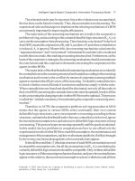
Influence of the excess-air factor λ on the power P
and on the specific fuel consumption be under conditions of homogeneous air/fuel-mixture distribution
induction air mass
theoretical air requirement
The lambda factor for a stoichiometric ratio
is λ 1.0. λ is also referred to as the excess-air
factor.
Richer fuel mixtures result in λ figures of
less than 1. Leaning out the fuel produces
mixtures with excess air: λ then exceeds 1. Beyond a certain point the mixture encounters
the lean-burn limit, beyond which ignition is
no longer possible. The excess-air factor has a
decisive effect on the specific fuel consumption (Fig. 3) and untreated pollutant emissions (Fig. 4).
Induction-mixture distribution in the
combustion chamber
Homogeneous distribution
The induction systems on engines with manifold injection distribute a homogeneous
air/fuel mixture throughout the combustion
chamber. The entire induction charge has a
single excess-air factor λ (Fig. 5a). Lean-burn
engines, which operate on excess air under
4
Effect of the excess-air factor λ on the pollutant
composition of untreated exhaust gas under conditions of homogeneous air/fuel-mixture distribution
HC
NOX
a
0.8
b
1.0
1.2
Excess-air factor λ
0.6
0.8
1.0
1.2
Excess-air factor λ
1.4
æ UMK0032-1E
be
Relative quantities of
CO; HC; NOX
P
æ UMK0033-1E
Fig. 3
a Rich air/fuel mixture
(air deficiency)
b Lean air/fuel mixture
(excess air)
Power P ,
specific fuel consumption be
CO
Basics of the gasoline (SI) engine
specific operating conditions, also rely on homogeneous mixture distribution.
Stratified-charge concept
A combustible mixture cloud with λ ≈ 1 surrounds the tip of the spark plug at the instant
ignition is triggered. At this point the remainder of the combustion chamber contains
either non-combustible gas with no fuel,
or an extremely lean air/fuel charge. The corresponding strategy, in which the ignitable
mixture cloud is present only in one portion of
the combustion chamber, is the stratifiedcharge concept (Fig. 5b). With this concept,
the overall mixture – meaning the average
mixture ratio within the entire combustion
chamber – is extremely lean (up to λ ≈ 10). This
type of lean operation fosters extremely high
levels of fuel economy.
5
Induction-mixture distribution in the combustion
chamber
a
æ UMK2080Y
b
Method of operation
11
Efficient implementation of the stratifiedcharge concept is impossible without direct
fuel injection, as the entire induction strategy
depends on the ability to inject fuel directly
into the combustion chamber just before ignition.
Ignition and flame propagation
The spark plug ignites the air/fuel mixture by
discharging a spark across a gap. The extent
to which ignition will result in reliable flame
propagation and secure combustion depends
in large part on the air/fuel mixture λ, which
should be in a range extending from λ =
0.75...1.3. Suitable flow patterns in the area
immediately adjacent to the spark-plug electrodes can be employed to ignite mixtures as
lean as λ ≤ 1.7.
The initial ignition event is followed by formation of a flame-front. The flame front’s
propagation rate rises as a function of combustion pressure before dropping off again
toward the end of the combustion process.
The mean flame front propagation rate is
on the order of 15...25 m/s.
The flame front’s propagation rate is the
combination of mixture transport and combustion rates, and one of its defining factors is
the air/fuel ratio λ. The combustion rate peaks
at slightly rich mixtures on the order
of λ = 0.8...0.9. In this range it is possible to approach the conditions coinciding with an ideal
constant-volume combustion process (refer to
section on “Engine efficiency”). Rapid combustion rates provide highly satisfactory fullthrottle, full-load performance at high engine
speeds.
Good thermodynamic efficiency is
produced by the high combustion temperatures achieved with air/fuel mixtures of
λ = 1.05...1.1. However, high combustion
temperatures and lean mixtures also promote
generation of nitrous oxides (NOX), which
are subject to strict limitations under official
emissions standards.
Fig. 5
a Homogeneous
mixture distribution
b Stratified charge
12
Basics of the gasoline (SI) engine
Cylinder charge
Cylinder charge
An air/fuel mixture is required for the combustion process in the cylinder. The engine
draws in air through the intake manifolds
(Fig. 1, Pos. 14), the throttle valve (13) ensuring that the air quantity is metered. The fuel
is metered through fuel injectors. Furthermore, usually part of the burnt mixture
(exhaust gas) from the last combustion is
retained as residual gas (9) in the cylinder or
exhaust gas is returned specifically to increase
the residual-gas content in the cylinder (4).
α
Throttle-valve angle
Components of the cylinder charge
The gas mixture trapped in the combustion
chamber when the intake valve closes is referred to as the cylinder charge. This is comprised of the fresh gas and the residual gas.
The term “relative air charge rac” has been
introduced in order to have a quantity
which is independent of the engine’s displacement. It describes the air content in
the cylinder and is defined as the ratio of
the current air quantity in the cylinder to
the air quantity that would be contained in
the engine displacement under standard
conditions (p0 = 1013 hPa, T0 =273 K). Accordingly, there is a relative fuel quantity rfq;
this is defined in such a way that identical
values for rac and rfq result in λ = 1, i.e.,
λ = rac/rfq, or with specified λ : rfq = rac/λ.
1
Cylinder charge in a gasoline engine
2
3
1
5
4
α
14
11
6
13
7
12
8
9
10
æ UMM0544-5Y
Fig. 1
1 Air and fuel vapor
(from evaporativeemissions control
system)
2 Canister-purge
valve with variable
valve-opening
cross-section
3 Connection to evaporative-emissions
control system
4 Returned exhaust
gas
5 Exhaust-Gas
Recirculation
valve (EGR valve)
with variable
valve-opening
cross-section
6 Air-mass flow
(ambient pressure pa)
7 Air-mass flow
(manifold pressure pm)
8 Fresh-gas charge
(combustionchamber pressure pc)
9 Residual-gas charge
(combustionchamber pressure pc)
10 Exhaust gas
(exhaust-gas
back pressure pe)
11 Intake valve
12 Exhaust valve
13 Throttle valve
14 Intake manifold
Fresh gas
The freshly introduced gas mixture in the
cylinder is comprised of the fresh air drawn
in and the fuel entrained with it. In a manifold-injection engine, all the fuel has already
been mixed with the fresh air upstream of
the intake valve. On direct-injection systems,
on the other hand, the fuel is injected directly into the combustion chamber.
The majority of the fresh air enters the
cylinder with the air-mass flow (Fig. 1,
Pos. 6, 7) via the throttle valve (13). Additional fresh gas, comprising fresh air and
fuel vapor, is directed to the cylinder via the
evaporative-emissions control system (3, 2).
For homogeneous operation at λ Յ 1, the
air in the cylinder directed via the throttle
valve after the intake valve (11) has closed
is the decisive quantity for the work at the
piston during the combustion stroke and
therefore for the engine’s output torque. In
this case, the air charge corresponds to the
torque and the engine load. Here, changing
the throttle-valve angle only indirectly leads
to a change in the air charge. First of all, the
pressure in the intake manifold must rise so
that a greater air mass flows into the cylinder
via the intake valves. Fuel can, on the other
hand, be injected more contemporaneously
with the combustion process and metered
precisely to the individual cylinder. Therefore the injected fuel quantity is dependent
on the current air quantity, and the gasoline
engine is an air-directed system in “conventional” homogeneous mode at λ Յ 1.
During lean-burn operation (stratified
charge), however, the torque (engine load) –
on account of the excess air – is a direct
product of the injected fuel mass. The air
mass can thus differ for the same torque.
The gasoline engine is therefore fuel-directed during lean-burn operation.
Basics of the gasoline (SI) engine
Almost always, measures aimed at increasing
the engine’s maximum torque and maximum output power necessitate an increase
in the maximum possible fresh-gas charge.
This can be achieved by increasing the engine displacement but also by supercharging
(see section entitled “Supercharging”).
Residual gas
The residual-gas share of the cylinder charge
comprises that portion of the cylinder charge
which has already taken part in the combustion process. In principle, one differentiates
between internal and external residual gas.
Internal residual gas is the exhaust gas which
remains in the upper clearance volume of the
cylinder after combustion or which, while
the intake and exhaust valves are simultaneously open (valve overlap, see section entitled
“Gas exchange”), is drawn from the exhaust
port back into the intake manifold (internal
exhaust-gas recirculation).
External residual gas is exhaust gas which
is introduced via an exhaust-gas recirculation valve (Fig. 1, Pos. 4, 5) into the intake
manifold (external exhaust-gas recirculation).
The residual gas is made up of inert gas 1)
and – in the event of excess air, i.e., during
lean-burn operation – of unburnt air. The
amount of inert gas in the residual gas is
particularly important. This no longer contains any oxygen and therefore does not participate in combustion during the following
power cycle. However, it does delay ignition
and slows down the course of combustion,
which results in slightly lower efficiency but
also in lower peak pressures and temperatures. In this way, a specifically used amount
of residual gas can reduce the emission of
nitrogen oxides (NOX). This then is the
benefit of inert gas in lean-burn operation
in that the three-way catalytic converter is
unable to reduce the nitrogen oxides in the
event of excess air.
1)
Components in the combustion chamber which behave
inertly, that is, do not participate in the combustion process.
Cylinder charge
In homogeneous engine mode, the fresh-gas
charge displaced by the residual gas (consisting in this case of inert gas only) is compensated by means of a greater opening of the
throttle valve. With a constant fresh-gas
charge, this increases the intake-manifold
pressure, therefore reduces the throttling
losses (see section entitled “Gas exchange”),
and in all results in reduced fuel consumption.
Gas exchange
The process of replacing the consumed
cylinder charge (exhaust gas, also referred to
in the above as residual gas) with fresh gas is
known as gas exchange or the charge cycle.
It is controlled by the opening and closing of
the intake and exhaust valves in combination with the piston stroke. The shape and
position of the camshaft cams determine the
progression of the valve lift and thereby influence the cylinder charge.
The opening and closing times of the
valves are called valve timing and the maximum distance a valve is lifted from its seat is
known as the valve lift or valve stroke. The
characteristic variables are Exhaust Opens
(EO), Exhaust Closes (EC), Intake Opens
(IO), Intake Closes (IC) and the valve lift.
There are engines with fixed and others with
variable timing and valve lifts (see chapter
entitled “Cylinder-charge control systems”).
The amount of residual gas for the following
power cycle can be significantly influenced
by a valve overlap. During the valve overlap,
intake and exhaust valves are simultaneously
open for a certain amount of time, i.e., the
intake valve opens before the exhaust valve
closes. If in the overlap phase the pressure
in the intake manifold is lower than that
in the exhaust train, the residual gas flows
back into the intake manifold; because the
residual gas drawn back in this way is drawn
in again after Exhaust Closes, this results in
an increase in the residual-gas content.
13
14
Basics of the gasoline (SI) engine
Cylinder charge
In the case of supercharging, the pressure before the intake valve can also be higher during
the overlap phase; in this event, the residual
gas flows in the direction of the exhaust train
such that it is properly cleared away (“scavenging”) and it is also possible for the air to
flow through into the exhaust train.
When the residual gas is successfully scavenged, its volume is then available for an increased fresh-gas charge. The scavenging effect
is therefore used to increase torque in the
lower speed range (up to approx. 2000 rpm),
either in combination with dynamic supercharging in naturally aspirated engines or
with turbocharging.
Volumetric efficiency and air consumption
The success of the gas-exchange process is
measured in the variables volumetric efficiency, air consumption and retention rate.
The volumetric efficiency is the ratio of the
fresh-gas charge actually remaining in the
cylinder to the theoretically maximum possible charge. It differs from the relative air
charge in that the volumetric efficiency is
referred to the external conditions at the time
of measurement and not to standard conditions.
The air consumption describes the total
air-mass throughput during the gas-exchange
process, likewise referred to the theoretically
maximum possible charge. The air consumption can also include the air mass which is
transferred directly into the exhaust train
during the valve overlap. The retention rate,
the ratio of volumetric efficiency to air consumption, specifies the proportion of the airmass throughput which remains in the cylinder at the end of the gas-exchange process.
The maximum volumetric efficiency for
naturally aspirated engines is 0.6...0.9. It depends on the combustion-chamber shape, the
opened cross-sections of the gas-exchange
valves, and the valve timing.
Pumping losses
Work is expended in the form of pumping
losses or gas-exchange losses in order to replace the exhaust gas with fresh gas in the
gas-exchange process. These losses use up
part of the mechanical work generated and
therefore reduce the effective efficiency of the
engine. In the intake phase, i.e., during the
downward stroke of the piston, the intakemanifold pressure in throttled mode
is less than the ambient pressure and in
particular the pressure in the piston return
chamber. The piston must work against this
pressure differential (throttling losses).
A dynamic pressure occurs in the combustion chamber during the upward stroke of
the piston when the burnt gas is emitted,
particularly at high engine speeds and loads;
the piston must expend energy in order to
overcome this pressure (push-out losses).
If with gasoline direct injection stratifiedcharge operation is used with the throttle
valve fully opened or high exhaust-gas recirculation is used in homogeneous operation
(λ Յ 1), this increases the intake-manifold
pressure and reduces the pressure differential
above the piston. In this way, the engine’s
throttling losses can be reduced, which in
turn improves the effective efficiency.
Supercharging
The torque which can be achieved during
homogenous operation at λ Յ 1 is proportional to the fresh-gas charge. This means that
maximum torque can be increased by compressing the air before it enters the cylinder
(supercharging). This leads to an increase in
volumetric efficiency to values above 1.
Dynamic supercharging
Supercharging can be achieved simply by
taking advantage of the dynamic effects inside
the intake manifold. The supercharging level
depends on the intake manifold’s design and
on its operating point (for the most part, on
engine speed, but also on cylinder charge).
The possibility of changing the intake-manifold geometry while the engine is running
(variable intake-manifold geometry) means
Basics of the gasoline (SI) engine
that dynamic supercharging can be applied
across a wide operating range to increase the
maximum cylinder charge.
Mechanical supercharging
The intake-air density can be further increased by compressors which are driven
mechanically from the engine’s crankshaft.
The compressed air is forced through the
intake manifold and into the engine’s
cylinders.
Exhaust-gas turbocharging
In contrast mechanical supercharging, the
compressor of the exhaust-gas turbocharger
is driven by an exhaust-gas turbine located
in the exhaust-gas flow, and not by the engine’s crankshaft. This enables recovery of
some of the energy in the exhaust gas.
Charge recording
In a gasoline engine with homogeneous
λ = 1 operation, the injected fuel quantity
is dependent on the air quantity. This is necessary because after a change to the throttlevalve angle the air charge changes only gradually while the fuel quantity can be varied
from injection to injection.
For this reason, the current available air
charge must be determined for each combustion in the engine-management system
(charge recording). There are essentially
three systems which can be used to record
the charge:
¼ A hot-film air-mass meter (HFM) measures the air-mass flow into the intake
manifold.
1)
The designation α/n system is historically conditioned
since originally the pressure after the throttle valve was
not taken into account and the mass flow was stored in
a program map covering throttle-valve angle and engine
speed. This simplified approach is sometimes still used
today.
Cylinder charge
¼ A model is used to calculate the air-mass
flow from the temperature before the
throttle valve, the pressure before and
after the throttle valve, and the throttlevalve angle (throttle-valve model,
α/n system 1)).
¼ A model is used to calculate the charge
drawn in by the cylinder from the engine
speed (n), the pressure (p) in the intake
manifold (i.e., before the intake valve),
the temperature in the intake passage and
further additional information (e.g., camshaft/valve-lift adjustment, intake-manifold changeover, position of the swirl control valve) (p/n system). Sophisticated
models may be necessary, depending on
the complexity of the engine, particularly
with regard to the variabilities of the valve
gear.
Because only the mass flow passing into the
intake manifold can be determined with a
hot-film air-mass meter or a throttle-valve
model, both these systems only provide a
cylinder-charge value during stationary engine operation. Stationary means at constant
intake-manifold pressure; because then the
mass flows flowing into the intake manifold
and off into the engine are identical.
In the event of a sudden load change
(change in the throttle-valve angle), the inflowing mass flow changes spontaneously,
while the off-flowing mass flow and with
it the cylinder charge only change if the
intake-manifold pressure has increased
or reduced. The accumulator behavior
of the intake manifold must therefore
also be imitated (intake-manifold model).
15
16
Basics of the gasoline (SI) engine
Torque and power
Direct-injection gasoline engines function
at certain operating points with excess air
(lean-burn operation). The cylinder thus
contains air, which has no effect on the generated torque. Here, it is the fuel mass which
has the most effect.
Torque and power
Torques at the drivetrain
The power P delivered by a gasoline engine
is defined by the available clutch torque M
and the engine speed n. The clutch torque
is the torque developed by the combustion
process less friction torque (friction losses in
the engine), pumping losses, and the torque
needed to drive the auxiliary equipment
(Fig. 1). The drive torque is derived from
the clutch torque plus the losses arising at
the clutch and transmission.
The combustion torque is generated in
the power cycle and is determined in engines with manifold injection by the following variables:
¼ The air mass which is available for combustion when the intake valves close
¼ The fuel mass which is available at the
same moment, and
¼ The moment in time when the ignition
spark initiates the combustion of the
air/fuel mixture
1
Generation of torque
The physical quantity torque M is the product of force F times lever arm s :
M = F·s
The connecting rod utilizes the throw of
the crankshaft to convert the piston’s linear
travel into rotary motion. The force with
which the expanding air/fuel mixture drives
the piston down the cylinder is converted
into torque by the lever arm generated by
the throw.
The lever arm l which is effective for the
torque is the lever component vertical to the
force (Fig. 2). The force and the leverage angle are parallel at Top Dead Center (TDC).
Torques at the drivetrain
1
1
2
3
4
Air mass
(fresh-gas charge)
Fig. 1
1 Auxiliary equipment
(A/C compressor,
alternator, etc.)
2 Engine
3 Clutch
4 Transmission
Ignition angle
(ignition point)
Engine
Gas exchange and friction
Auxiliary equipment
Clutch losses
Transmission losses and ratio
Combustion
torque
Engine
torque
–
Clutch
torque
–
Clutch
–
Drive
Trans- torque
mission
–
æ UMM0545-3E
Fuel mass