Assessment of non linear regression approach for back-analysis on tunnelling-induced surface settlement: A case study in Ho Chi Minh city
Bạn đang xem bản rút gọn của tài liệu. Xem và tải ngay bản đầy đủ của tài liệu tại đây (574.1 KB, 7 trang )
32
Journal of Transportation Science and Technology, Vol 33, Aug 2019
ASSESSMENT OF NON-LINEAR REGRESSION APPROACH FOR
BACK-ANALYSIS ON TUNNELLING-INDUCED SURFACE
SETTLEMENT– A CASE STUDY IN HO CHI MINH CITY
ĐÁNH GIÁ PHƯƠNG PHÁP HỒI QUY PHI TUYẾN TRONG PHÂN TÍCH ĐỘ LÚN
MẶT ĐẤT GÂY RA BỞI THI CÔNG HẦM – NGHIÊN CỨU TRƯỜNG HỢP
TẠI THÀNH PHỐ HỒ CHÍ MINH
Le Thanh Binh*, Nguyen Anh Tuan, Nguyen Trong Tam
Ho Chi Minh City University of Transport, Vietnam
*
Abstract: Previous researchers proved that surface settlement induced by tunnel constructions can
be described by a Gaussian curve with the two key parameters K, the trough width factor, and V L , the
volume loss. Knowing K and V L values enables surface settlement trough to be calculated which is
essential to determine the potential effects of tunnelling to soil and surrounding buildings. A non-linear
approach has been widely used to estimate K and V L values from field measurement using the sum of
absolute errors. However, the reliability of the determined results could not be quantified. This paper
uses surface settlement data from a case study in a tunnelling project in Ho Chi Minh city to determine
K and V L using the non-linear regression approach. Then, a method was proposed to quantify the
goodness of fit and the reliability of the determined K and V L . The results show that knowing the
reliability of the K and V L is essential for the designers and researchers to determine if these values
should be used as reference for their calculation in a similar tunnelling project to predict surface
settlement.
Keywords: Tunnelling, case study, empirical method, field data, non - linear regression.
Chỉ số phân loại: 2.4
Tóm tắt: Các nhà nghiên cứu trước đã chứng minh rằng độ lún mặt đất gây ra bởi việc thi công
hầm có dạng đường cong Gaussian với hai thông số chính là K, trị số bề rộng, và V L , thể tích mất mát
đất. Từ K và V L , đường cong lún có thể được tính toán để đánh giá các ảnh hưởng tiềm năng của việc
thi công hầm đến đất và công trình lân cận. Phương pháp hồi quy phi tuyến được sử dụng rộng rãi để
ước lượng giá trị K và V L dựa vào số liệu hiện trường thông qua tổng sai số tuyệt đối. Tuy nhiên, độ tin
cậy của các giá trị này không được định lượng. Bài báo này sử dụng số liệu hiện trường từ công trình
thi công hầm tại thành phố Hồ Chí Minh để xác định giá trị K và V L theo phương pháp hồi quy phi
tuyến. Sau đó, một phương pháp bổ sung được đề xuất để định lượng độ chính xác và độ tin cậy của cặp
giá trị K và V L . Kết quả cho thấy việc biết được độ tin cậy của giá trị K và V L là rất quan trọng cho đơn
vị thiết kế và các nhà nghiên cứu trong việc lựa chọn các giá trị này khi tính toán và dự đoán độ lún của
mặt đất gây ra bởi thi công hầm tương tự trong tương lai.
Từ khóa: Thi công hầm, phương pháp thực nghiệm, dữ liệu hiên trường, hồi quy phi tuyến
Classification number: 2.4
1. Introduction
1.1. The overview of tunnel construction
In many urban environments the available
over ground space is no longer adequate to
sustain construction of new transportation
systems to serve the growing traffic and
congestion. This has led to an increase in the
number of tunnelling projects for services and
mass transit systems. Following this inevitable
trend, a total of nearly 100km of tunnels, as a
part of the metro line systems, have been
planned in Hanoi and Ho Chi Minh City [1 4]. Basically, tunnelling is to create space for
underground services by removing soil and
replacing it by tunnels. Mair et al [7] reported
that there are several methods to excavate
tunnels including sprayed concrete lining (or
sometime referred as New Austrian
Tunnelling Method, NATM) and tunnel
boring machine (TBM).
Nowadays, TBM are often used due to its
advantageous capabilities including fast
construction, better controlled ground
movement, safety for workers and
surrounding structures, minimal disruption to
structures and activities on the surface etc
TẠP CHÍ KHOA HỌC CÔNG NGHỆ GIAO THÔNG VẬN TẢI, SỐ 33-08/2019
([5]). The tunnel in the line number 1 Ben
Thanh Suoi Tien, Ho Chi Minh city was
constructed using an Earth Pressure Balance
Tunnel Boring Machine (EPB TBM) as the
method is suitable with the soil condition in
the area.
1.2. Tunnel construction using EPB
TBM
The key aspect of an EPB TBM is the
provision of adequate support at the tunnel
face during excavation to control soil
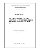
displacement [8]. Typical features of an EPB
TBM are depicted in figure 1 [8].
During tunnelling process, the cutter head
(1), powered by motor (2), excavates the soil
under the cover of the tunnel shield (3). The
excavated soil passes through the cutter head
then enters the pressurised chamber which is
immediately behind the cutter head. The
excavated soil in the chamber is then extracted
through a screw conveyor (5) to the discharge
outlet (7) that leads to the conveyor belt (9)
where the soil is transported to the outside of
the tunnel. The speed of soil extraction from
the chamber can be adjusted, i.e. fast
extraction of soil will lead to decrease of
chamber pressure and vice versa, to achieve
the desired pressure in the chamber to balance
earth pressure at the tunnel face. After each
excavation cycle, tunnel lining segments (8)
are erected within the TBM tail skin (3). As
the tail of the tunnel leaves the tunnel lining,
pressurised grout is injected behind the
segments to fill the void between the external
side of the tunnel lining and the excavated
ground [8]. The cycle of excavation, lining
segment erection and grout injection repeats
until the completion of the designed tunnel.
33
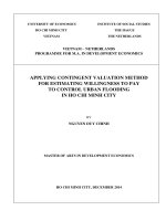
1.3. Ground loss in TBM tunnelling
In TBM tunnelling, during the excavation
of soil and installation of tunnel lining, soil
deformations occur because of the five main
sources (Figure 2) which are corresponding to
the consequential construction stages as
described below [9]:
- Face movement: caused by changes in
soil stress due to excavation and the
application of face pressure, provided at the
TBM front, to balance earth pressure at this
location. If the face pressure is smaller than
soil and water pressures, then the ground mass
in front of the tunnel will move towards the
tunnel face.
- Over-excavation: it is common that the
TBM cutter is larger than the tunnel diameter
which causes over-excavation. This creates a
gap between the excavated soil and the tunnel
shield which allows ground to move towards
the tunnel vicinity before stage 4 takes place.
- Shield tapering: for the ease of moving
the TBM forward, the front of the TBM is
normally larger than its end.
- Tail void closure: before the erection of
tunnel lining and injection of grout, soils
behind the TBM tail tend to move into the
tunnel vicinity. The key factors that affect this
component of soil movements are: soil
properties, volume and speed of grout
injection to fill the void, the speed of
excavation.
Lining deformation: earth and pore water
pressures cause deformations in tunnel lining.
This component depends on some key factors
including soil properties, depth of tunnel,
water table level, properties of tunnel lining.
Figure 1. Earth Pressure Balance Tunnel Boring Machine (EPB TBM):
1- Cutter head; 2 - Drive motor; 3 - TBM skin; 4 - Airlock; 5 - Screw conveyor; 6 - Lining erector arm;
7 - Soil discharge; 8 - Lining segments; 9 - Belt conveyor [8].
34
Journal of Transportation Science and Technology, Vol 33, Aug 2019
Figure 2. Components of volume loss in TBM tunnelling [9].
Figure 3. Tunnelling-induced soil settlement (after [6]).
The mentioned components caused soil
deformations around the tunnel that results in
settlement at the surface (Figure 3). These
ground displacements may cause destructive
damages to surrounding buildings. Therefore,
predictions on the effects of tunnel
construction to the deformations of soil and
surrounding structures are very important to
ensure the success of tunnelling projects.
2. Prediction of tunnelling-induced
surface settlement
2.1. The shape of settlement trough
Previous researchers ([6], [7], [9], [10],
[13], [14], [15]) demonstrated that the profile
of tunnelling induced surface settlement has
the shape of an inverse Gaussian curve (figure
4) and can be described by equation 1.
The parameters in Equations 1 are
depicted in Figure 4.
-y2
𝑆𝑆 = 𝑆𝑆𝑚𝑚𝑚𝑚𝑚𝑚 𝑒𝑒𝑒𝑒𝑒𝑒 �2𝑖𝑖 2 �
Where:
𝑆𝑆 is surface settlement,
(1)
𝑦𝑦 is the distance from the tunnel centre
line to the settlement point in the transverse
direction;
𝑆𝑆𝑚𝑚𝑚𝑚𝑚𝑚 is the maximum settlement
(usually corresponding to 𝑦𝑦 = 0);
𝑖𝑖 is the distance from the centreline to the
point of inflexion in transverse direction.
Where:
𝑆𝑆𝑚𝑚𝑚𝑚𝑚𝑚 = 𝑉𝑉𝑆𝑆 ⁄√2𝜋𝜋𝑖𝑖 ;
𝑉𝑉𝑆𝑆 =𝑉𝑉𝐿𝐿 × 𝑉𝑉𝑒𝑒𝑒𝑒𝑒𝑒 ;
(2)
(3)
𝑖𝑖 = 𝐾𝐾𝑧𝑧0
(5)
𝑉𝑉𝑒𝑒𝑒𝑒𝑒𝑒 =𝜋𝜋
𝐷𝐷 2
4
;
(4)
𝑉𝑉𝑆𝑆 is the magnitude of the settlement
trough;
𝑉𝑉𝑒𝑒𝑒𝑒𝑒𝑒 is the volume of excavation area;
𝑉𝑉𝐿𝐿 is the volume loss that indicates the
ratio of 𝑉𝑉𝑆𝑆 with 𝑉𝑉𝑒𝑒𝑒𝑒𝑒𝑒 ;
𝐷𝐷 is the excavation diameter.
Combining (2), (3), (4) and (5) gives:
𝑆𝑆𝑚𝑚𝑚𝑚𝑚𝑚 =0.313
𝑉𝑉𝐿𝐿 𝐷𝐷 2
𝐾𝐾𝑧𝑧0
(6)
TẠP CHÍ KHOA HỌC CÔNG NGHỆ GIAO THÔNG VẬN TẢI, SỐ 33-08/2019
35
Replacing Equations (5) and (6) to
Equation (1), S can be calculated as;
𝑆𝑆 = 0.313
𝑽𝑽𝑳𝑳 𝐷𝐷 2
𝑲𝑲𝑧𝑧0
-y2
𝑒𝑒𝑒𝑒𝑒𝑒 �2(𝑲𝑲𝑧𝑧
2
0)
�
(7)
In Equation 7, the tunnel diameter D and
the tunnel depth 𝑧𝑧0 are known and constant at
a specific location. Therefore, the profile of
the settlement curve, 𝑆𝑆, depends on the values
of volume loss 𝑉𝑉𝐿𝐿 and 𝐾𝐾. Discussion on these
two values are presented in the following
sections.
Figure 4. Usage of Gaussian curve to represent
settlement trough [7].
2.2. Volume loss 𝑽𝑽𝑳𝑳
Volume loss V L together with K govern
the maximum soil settlement S max (Equation
6). Volume loss 𝑉𝑉𝐿𝐿 depends on many factors
including
soil
conditions,
tunnelling
technique, tunnel geometry and quality of
workmanship hence it is difficult to estimate
𝑉𝑉𝐿𝐿 . A common approach to predict 𝑉𝑉𝐿𝐿 is to use
field data from case studies of similar projects
and engineering judgement.
2.3. Settlement trough width parameter
K
The width of the settlement trough is
dictated by the value i = Kz 0 and the
settlement trough width can extend up to 3𝑖𝑖 =
3Kz 0 . The dimensionless parameter K varies
within a wide range of 0.25 to 0.7 and it
depends on soil conditions. Figure 5 illustrates
the need for determination of K in assessment
of the effects caused by tunnelling.
Figure 5. Influence of K to the width of
the settlement curve (after [8]).
It can be seen from Figure 5, that for large
K (wider settlement curve) the building will be
in the influenced zone and will need to be
examined for the tunnelling - induced effects.
On the other hand, for small K, the building is
out of the influenced zone hence there is no
need to assess the tunnelling effects.
Therefore, a good prediction of K is of
paramount importance to determine the width
of the settlement trough and hence the area
affected by ground settlement due to
tunnelling.
In order to make good predictions,
reference database, including movements of
soil caused by tunnel construction in local
regions are vital. Those reference data could
provide useful values of K and V L which
enable the settlement trough caused by tunnel
construction to be estimated using Equation 1.
A common method to determine the values of
K and V L from the field data is the non-liner
approach suggested by [11].
3. The non - linear regression method
[11] proposed a nonlinear regression
method to estimate parameters 𝐾𝐾 and 𝑉𝑉𝐿𝐿 . The
procedure involves varying the two
parameters K and 𝑉𝑉𝐿𝐿 and calculating the
corresponding sum of absolute errors (SAE).
The “best-fit” is defined as the combination of
𝐾𝐾 and 𝑉𝑉𝐿𝐿 that results in the smallest 𝑆𝑆𝑆𝑆𝑆𝑆. The
𝑆𝑆𝑆𝑆𝑆𝑆 is calculated as the difference between
the measured data (S M ) and the empirical
calculation using equation 1 (S E ):
𝑚𝑚 |
𝑆𝑆𝑆𝑆𝑆𝑆 = ∑𝑛𝑛𝑚𝑚=1|𝑆𝑆𝐸𝐸𝑚𝑚 − 𝑆𝑆𝑀𝑀
=
�0.313
𝑽𝑽𝑳𝑳 𝐷𝐷 2
𝑲𝑲𝑧𝑧0
-𝑦𝑦 2
𝑚𝑚
𝑒𝑒𝑒𝑒𝑒𝑒 �2(𝑲𝑲𝑧𝑧𝑚𝑚 )2 � − 𝑆𝑆𝑀𝑀
�
0
(8)
36
Journal of Transportation Science and Technology, Vol 33, Aug 2019
Where: 𝑛𝑛 is the total number of
measurement points.
The best-fit values of K and V L can be
found by using the solver function in Excel or
the curve-fitting application in Matlab. The
two main advantages of non-linear regression
method are:
- It is straightforward which involves
non-linear regression calculation to obtain K
and 𝑉𝑉𝐿𝐿 ;
- The results are objective as they are
based on the calculated SAE.
However, the non-linear approach does
not present the reliability of the obtained
values. This paper seeks to improve this
aspect by proposing a method to quantify and
assess the reliability of obtained values using
field measurements from a case study of
tunnel construction in Ho Chi Minh city.
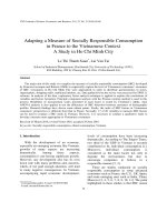
4. The case study in Ho Chi Minh city
The total length of the line is 19.7km
which includes 781m of twin tunnels. The
East-Bound (EB) tunnel was constructed first
and the West-bound (WB) tunnel was
constructed later. The purpose of this paper is
to assess the reliability of the determined K
and V L values hence only data from the EB
tunnel will be used to avoid the effects of
interaction between the two tunnels.
Field measurement at the two locations
km 1 + 403 and km 0 + 983 were chosen to be
a) Km 1+403
studied in this paper. The reasons being was
in these areas, the monitoring points were far
from existing buildings hence soil settlement
was caused by tunnel excavation only and the
effects of surface structure were negligible.
This makes settlement values suitable for
greenfield analysis.
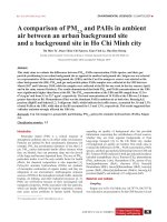
The ground, at those two locations,
comprises of five different layers as illustrated
in figure 6 and described below:
- Fill: sand, clay, gravel, brick, concrete,
yellowish grey, yellowish brown;
- AC2 (Alluvial clay): fat CLAY, bluish
grey, very soft to soft;
- AS1 (Alluvial sand): silty SAND/clayey
SAND, somewhere with organic, gravel,
blackish grey, bluish grey, brownish grey,
yellowish grey, medium stiff to stiff,
somewhere soft;
- AS2 (Alluvial sand): silty SAND/Silty
clayey SAND, yellowish grey, bluish grey,
whitish grey, medium dense;
- DC (Diluvium clay): Lean CLAY/fat
CLAY/clayey silt, yellowish brown, bluish
grey, brownish grey, very stiff to hard.
The EB tunnel lied completely in the
layer AS2 at those two considered sections.
The depth of the EB tunnel at section km
1+403 and km 0+983 are 17.6m and 24.1n
below the ground surface.
b) Km 0+983
Figure 6. Tunnel arrangements and geotechnical profiles [12].
37
TẠP CHÍ KHOA HỌC CÔNG NGHỆ GIAO THÔNG VẬN TẢI, SỐ 33-08/2019
5. Assessment on the calculated values of
K and V L
Calculation using the non-linear
regression method were conducted that gives
two pairs of K and V L for the two locations as
below.
- Km 1+403: K=368; V L =0.15%.
- Km 0+983: K=0.204; V L =0.021%.
In order to assess the reliability of the
determined K and V L , this paper proposes to
use a factor called the goodness of fit
formulated as below;
𝑆𝑆𝐴𝐴𝐴𝐴
𝐺𝐺 = (1 − |𝑆𝑆𝑆𝑆𝑆𝑆|) × 100
(9)
Where:
G is goodness of fit;
SoS is Sum of Settlement.
Table 1 presents calculated values in the
non-linear regression analysis and G for km
1+403 in which 7 monitoring points (P1 to P7)
were used.
Similarly, calculation of G for km 0+983
was carried out and the value of G was 37%
with the best-fit K=0.204; V L =0.021%. At this
stage, it can be seen that those obtained values
are not reliable due to low G.
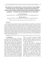
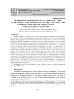
In order to illustrate the goodness of fit of
the empirical settlement trough, calculated by
Equation 1 using the determined K and V L ,
with the measured data, Figure 7 compares
surface settlement from field measurement
and the empirical calculation at the two
locations due to EB tunnel constructions.
From Figure 7.a, it can be seen that the
empirical settlement trough fits well with the
field data which is confirmed by the high
value of goodness of fit G=94.5%. In contrast,
for km 0+983, the goodness of fit value is low
G=37% which reflects the poor fit of the
empirical settlement trough with the field
measurement (Figure 7.b).
It is important to note that the tunnel at
the two locations were in the same soil layer
but the K values determined from the nonlinear regression analysis were almost two
times different.
Table 1. Calculation values in non-linear
regression method for km 1+403.
P1
P2
P3
P4
P5
P6
P7
Y (m)
-6.4
-3.2
0
3.1
6.7
11
14.7
S M (mm)
-2.1
-2.9
-3.4
-3.0
-1.7
-0.6
-0.2
S E (mm)
-2.0
-2.9
-3.3
-2.9
-1.9
-0.8
-0.3
AE (mm) (10-2)
9
1
14
8
22
18
5
SAE (mm)
0.81
SoS (mm)
-14.07
G (%)
94.5%
-20
Distance to tunnel CL, y (mm)
-10
0
10
20
0.00
30
-1.00
-2.00
-3.00
-4.00
Field
measurement
Empirical
-30
Settlement, S (mm)
Settlement, S (mm)
-30
-20
Distance to tunnel CL, y (m)
-10
0
10
20
0
30
-0.2
-0.4
-0.6
-0.8
-1
a) Km 1+403
b) Km 0+983
Figure 7. Comparison on surface settlement from field measurements
and empirical calculations (EB tunnel construction).
Field
measurement
Empirical
38
Journal of Transportation Science and Technology, Vol 33, Aug 2019
This implies one of the values is not
reliable. Knowing the goodness of fit G is
beneficial to determine the reliability of the
determined K and V L before plotting the
empirical settlement trough or adopting the K
values for further calculation.
6. Conclusion
The original non-linear regression
method offers an objective approach to
estimate the two key values K and V L that best
fit with the field data. However, the
calculation from the non-linear regression
approach itself does not indicate the reliability
or the goodness of fit between the empirical
settlement trough and the field data.
By using the factor G proposed in this
paper, the goodness of fit can be estimated
which is simple and useful to decide if the
determined K and V L values are reliable and
provide good fit. In addition, this method can
be used to quantify the goodness of fit of the
calculated settlement through for other
methods such as finite element analysis with
field measurement.
For analysis that involves large amount of
field measurements, the simple calculation of
G factor proposed in this paper offers robust
assessment on the reliability of the K and V L
values obtained from the non-linear
regression method
Acknowledgement
The authors acknowledge the Ministry of
Transport of Vietnam for their funding for this
research (Grant no. DT183048) and Ho Chi
Minh city University of Transport for their
support.
References
[1] Decision number 568/QĐ-TTg of Vietnam
Government dated 8/4/2013 regarding approval of
Plan of Transportation development in Ho Chi
Minh city to 2020 with vision after 2020.
[2] Decision number 1259/QĐ-TTg dated 26/7/2011 of
Vietnam Government regarding Master plan of the
capital city to 2030 with vision to 2050.
[3] Decision number 214/QĐ-TTg dated 10/02/2015 of
Vietnam Government regarding approval of Strategy
for development of Railway transportation in
Vietnam to 2020 with vision to 2050.
Decision number 1468/QĐ-TTg dated 24/8/2015 of
Vietnam Government regarding changes in Master
Plan for Railway transportation of Vietnam to 2020
with vision to 2030.
[4] Chapman, D.N., Metje, N. and Stark, A., 2017.
Introduction to tunnel construction. Crc Press.
[5] B.T. Le, R.N. Taylor. 2018. Soils and
Foundations. Response of clay soil to threedimensional tunnelling simulation in centrifuge
models.
[6] Mair, R.J. and Taylor, R.N., 1997. Theme lecture:
Bored tunnelling in the urban environment. In
Proceedings of the fourteenth international
conference on soil mechanics and foundation
engineering (Hamburg, 1997), Balkema (pp. 23532385).
[7] Mair, R.J., 2008. Tunnelling and geotechnics: new
horizons. Géotechnique, 58(9), pp.695-736.
[8] Wan, M.S.P., Standing, J.R., Potts, D.M. and
Burland, J.B., 2017. Measured short-term ground
surface response to EPBM tunnelling in London
Clay. Geotechnique 67.
[9] O'Reilly, M.P. and New, B.M., 1982. Settlements
above tunnels in the United Kingdom-their
magnitude and prediction. Tunnelling 82. Third
International Symposium, the Institution of
Mining and Metallurgy.
[10] Jones, B. and Clayton, C., 2013. Guidelines for
Gaussian curve-fitting to settlement data. In
Underground–The Way to the Future: Proceedings
of the World Tunnel Congress, CRC Press, Boca
Raton, Fla (pp. 645-652).
[11] Soil investigation report for the metro line in Ho
Chi Minh city, Vietnam.
[12] Dimmock, P.S., 2003. Tunnelling-induced ground
and building movement on the Jubilee Line
Extension. PhD thesis, University of Cambridge.
[13] Peck, R.B., Hendron, A.J. and Mohraz, B., 1972,
June. State of the art of soft-ground tunneling. In N
Am Rapid Excavation & Tunneling Conf Proc
(Vol. 1).
[14] DeJong, M.J., Giardina, G., Chalmers, B., Lazarus,
D., Ashworth, D. and Mair, R.J., 2019. The impact
of the Crossrail tunnelling project on masonry
buildings with shallow foundations. Proceedings
of the Institution of Civil Engineers-Geotechnical
Engineering, pp.1-35.
Ngày nhận bài: 14/5/2019
Ngày chuyển phản biện: 17/5/2019
Ngày hoàn thành sửa bài: 7/6/2019
Ngày chấp nhận đăng: 14/6/2019