Biến Tần Panasonic VF-0 Và VF-CE Series
Bạn đang xem bản rút gọn của tài liệu. Xem và tải ngay bản đầy đủ của tài liệu tại đây (825.87 KB, 16 trang )
Motion Control
AC Inverters VF-0, VF-CE
02/2006
2
AV Inverters VF-0, VF-CE
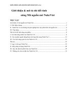
Product Overview
1-phase 230V AC
0.2kW
0.4kW
0.75kW
1.5kW
3-phase 400V AC
0.75kW
1.5kW
2.2kW
3.7kW
VF-0 Series
- Ultra-compact
- Easy to use
- Cost effective
VF-CE Series
- Vector control
- Advanced technology
- Filter integrated
- Multiple interfaces
(RS232C/RS485, PROFIBUS)
1-phase 230V AC
0.25kW
0.37kW
0.75kW
1.5kW
2.2kW
3-phase 400V AC
0.75kW
1.5kW
2.2kW
4.0kW
02/2006
3
MotorPower P
N
Part No.
[kW]
0.75 BFV00074
1.5 BFV00154
2.2 BFV00224
3.7 BFV0
0374
Easy and accurate frequency control with a PLC
Frequency control with a PWM signal from a PLC to the inverter is possible without analogue I/O units. Motor speed can be controlled.
VF-O
PLC/FP0
Easy to operate
- Ultra-compact
- Easy to operate using the integrated operating panel
- Cost effective
- Easy and accurate frequency control using PLC puls
output
- Various types without and with brake included (1-phase)
- 8-speed control function
- Retry function
- Frequency increase, decrease and memory functions
using external switches
- Complete regeneration brake function
Highlights
1-phase 230V AC Input types
Part No.
MotorPower P
N
Brake
[kW] provided not provided
0.2 BFV00022DK
0.4 BFV00042GK BFV00042DK
0.75 BFV00072GK BFV00072DK
1.5 BFV00152GK BFV00152DK
3-phase 400V AC Input types
Button to select „frequency output, cur-
rent display“, „frequency setting, moni-
tor“, „rotation direction setting“,„function
setting“ and switching the display to
show data or mode
Display shows output frequency, current,
line speed, error details, data for function
setting and parameter numbers
Button to start the inverter
Button to stop the inverter
Up/Down buttons to change the data and
output frequency, and to set forward or
reverse run direction
Button to change the display between the
parameter No. and data display, and sa-
ve the data, also to change between fre-
quency and current display
Potentiometer to set the operating frequency
Motor
VF-0 Series
Overview
02/2006
4
VF-0 Series
Specifications
Applied motor output
Input
power supply
Rated
output
Output
frequency
OperationControlBrakingOutput signalProtectionEnvironment
Display
0.2 to 1.5kW 0.75 to 3.7kW
Rated output voltage
3-phase 200 to 230V AC (proportional to power supply voltage) 3-phase 380 to 460V AC (proportional to power supply voltage)
Overload current rating 150% of rated output current for 1 minute
Phases, voltage, frequency 1-phase 200 to 230V AC 50/60Hz 3-phase 380 to 460V AC 50/60Hz
Tolerable voltage variations +10%, –15% of rated AC input voltage
Torerable frequency variations ±5% of rated input frequency
Instantaneous voltage
drop resistance capacity
Continuous operation at 165V or more.
Continuous operation at less than 165V for 15ms
Output frequency range 0.5 to 250Hz
Frequency display Digital display
Frequency accuracy ±0.5% of selected maximum set frequency (25±10°C) for analogue setting
Frequency setting resolution Digital setting: 0.1Hz (1Hz over 100Hz), Analogue setting: 0.1Hz (50/60Hz mode)
Inverter control method High carrier frequency sinusoidal PWM control (V/F control method)
Carrier frequency
Select from 9 types
(The output current must be reduced for 12.5 and 15.0kHz)
(0.8, 1.1, 1.6, 2.5, 5.0, 7.5, 10, 12.5, 15kHz)
Select from 7 types
(0.8, 1.1, 1.6, 2.5, 5.0. 7.5, and 10kHz)
(The output current of 3.7kW must be reduced when set to 10kHz.)
Start/Stop Operation panel buttons or input
contact signal (wait time setting possible)
Forward/Reverse Operation panel buttons or input
contact signal (reverse rotation prohibit setting possible)
Jog operation
O
perating frequency: Optional setting for 0.5 to 250Hz, Acceleration/deceleration time: Optional setting each for 0.04 to 999 seconds
Stop mode Select from ramp-to-stop or coast-to-stop (selection changeover)
Reset function Stop signal reset, external reset, panel reset (setting possible) and power supply reset
Stop frequency Optional setting from 0.5 to 60Hz
Instantaneous power failure restart Function OFF, and 0Hz restart, operating frequency restart (selection changeover)
Retry function Retry selection: Select function OFF and details of retry fault, No. of retries: Optional setting for 1 to 10 times
Frequency setting signal
• Local setting: Potentiometer, digital setting (operation panel)
• External analog setting signal: Potentiometer (10kW, 1/4 or more), 0 to 5V, 0 to 10V,
4 to 20mA (Connect a 200 , 1/4W or more external resistor)
•
External digital setting signal: PWM signal (signal cycle: 0.9 to 1100ms), Frequency up SW, down SW, save SW signal
Voltage/frequency characteristics
Base frequency: 50, 60Hz fixed and optional setting between 45 and 250Hz
V/F curve: Constant torque, square torque pattern (selection changeover)
2nd voltage/frequency characteristics Optional base frequency setting for 45 to 250Hz
Optional setting for 0 to 40%1st and 2nd torque boost level
1st and 2nd accel./Decel. Time 0.04 to 999sec. (individual accel. and decel. Time setting), Accel./Decel. Characteristics: Linear
Multi-speed frequency setting Up to 8 preset frequency settings (optional setting)
Skip frequency setting Up to 3 place settings (skip frequency band setting from 1 to 10Hz)
Upper and lower frequency setting Optional setting from 0.5 to 250Hz
Bias/gain frequency settings Bias frequency: set from –99 to 250Hz, Gain frequency: set from 0 to 250Hz
External stop function Select from auxiliary stop or coast-to-stop (selection setting)
Regenerative
braking torque
With brakes 0.4kW, 0.75kW, 1.5kW: 100% or more (short-time)
20% or more
100% or more with connection of brake resistor (option)
(built-in brake circuit)
Without brakes
0.2kW: 100% or more, 0.4kW: 80% or more
0.75kW: 20% or more, 1.5kW: 20% or more
DC braking
Operates when less than stop frequency, Braking torque level: 0 to 100 (set between 20 levels),
Braking time: Optional setting for 0.1 to 120 seconds
Analogue output
Output specifications: 0 to 5V (max. 1mA), Output functions: Output frequency, output current proportional (selection changeover)
Open collector output
Output specifications: Max. rating 50V DC, 50mA
Output functions: Run signal, arrival signal, overload prealarm, freuquency detection, reverse run signal,
fault warning, output frequency/current proportional PWM signal (cycle 1ms)
Relay output
Output specifications: change over (1c) contact (contact capacity 250V AC, 0.5A resistance load)
Output functions: Run signal, arrival signal, overload prealarm, frequency detection, reverse run signal, fault warning
Operating condition Output frequency or line speed (selection changeover), output current, rotation direction
Fault details Symbol indicated when protective function activates (last 4 faults are stored)
Current limit Current limit can be set from 1 to 200% of rated output current
Shut-off (stop)
Instantaneous overcurrent, over temperature (SC1 to 3), overcurrent (OC 1 to 3), overload/electronic thermal overload (OL),
low voltage (LU), overvoltage (OU 1 to 3), auxiliary stop (AU), operation error (OP)
Stall prevention function Overcurrent stall prevention, regenerative overvoltage stall prevention
Working ambient temperature and humidity
–10°C to +50°C (with no freezing), 90% RH or less (with no dew condensation)
Transportation/storage temperature and humidity
–25°C to +65°C, 95% RH or less
Altitude and vibration 1000m or less, 5.9m/s
2
(0.6G) or less
Atmosphere Indoors, with no corrosive gases, explosive gases, oil mist or dust present
Enclosure IP00
Cooling method
• Protection against Electric shock: Class I • Overvoltage category: II • Pollution degree: 2
Note: The specifications for the 200V and 400V classes are not the same. Please keep in mind this partial difference.
Self-cooling: 0.2 to 0.75kW, Forced-air cooling: 1.5kW Self-cooling: 0.75kW, Forced-air cooling: 1.5 to 3.7kW
Input voltage
1-phase 230V AC
Continuous operation at 323V or more.
Continuous operation at less than 323V for 15ms
3-phase 400V AC
1)
1)
1)
1a = Normally open
02/2006
5
VF0
VF0
5 mm
5 mm
W
W1
W
W1
H
H1
H
8 mm
5 mm
H1
D
D
7 mm
8 mm
W2
Ø
5 mm
Ø
5 mm
1-phase 230V AC
3-phase 400V AC
Part No. Applicable W W1 H H1 D
Motor [mm] [mm] [mm] [mm] [mm]
Capacity
[kW]
BFV00022DK 0.2
BFV00042DK 0.4 78 68 110 102 100
BFV00042GK 0.4
BFV00072DK 0.75
BFV00072GK 0.75
100 90 130 121 115
BFV00152DK 1.5
BFV00152GK 1.5
Part No. Inverters W W1 W2 H H1 D
Capacity [mm] [mm] [mm] [mm] [mm] [mm]
[kW]
BFV00074 0.75 130 121 110 130 90 148
BFV00154 1.5
130 121 110 130 90 161
BFV00224 2.2
BFV000334 3.7 160 151 140 130 90 161
Filters
Dimensions
Brake resistor
EMC filters are usually employed to reduce conducted disturbances and thus ensure constant quality in the power supply network.
For use, the standards EN61800-3 (product standard) and EN55011/EN55022 (limits and methods of measurement) are important, whereby the fol-
lowing limits must be met: EN55011/EN55022, Class A: Limits for general industrial use. This applies to all usage sites that are normally connected
to their own individual high- of medium-high voltage transformer.
Note 1: 1.5kW includes a cooling fan
Note 1: 1.5 to 3.7kW includes a cooling fan
Inverter P
N
EMC Filter Compliant to Part No.
VF-0 1-phase 0.2kW – 1.5kW 200V type EN55022 Class A and B FN2071N606
VF-0 3-phase 0.75kW – 3.7kW 400V type EN55022 Class A and B FN3258745
VF-0 Part No. Motor [kW] Part No. Dimensions [mm]
BFV00074 0.75kW 3-phase 400V BFVC9164U 110 x 80 x 15
BFV00154 1.5kW 3-phase 400V BFVC9164U 110 x 80 x 15
BFV00224 2.2kW 3-phase 400V BFVC9165U 110 x 80 x 15
BFV00374 3.7kW 3-phase 400V BFVC9166U 216 x 80 x 15
For 1-phase 230 V AC types please select the BFV00042GK, BFV00072GK or BFV00152GK.
The brake resistor is either enclosed, or built in.
VF-0 Series
Specifications
Brake resistor
02/2006
6
VF-CE Series
Overview
• Ultra-compact
• Integrated filter with EMC interference to class B
• Vector control and V/f control
• Up to 1.8 x M
N
torque for 60s (M
N
= rated load torque)
• Multiple interfaces
(digital/analogue I/O, RS232/RS485, PROFIBUS)
• Operator module with copy function
• International approvals (CE, UL, cUL)
• Cost effective
• Energy efficient
• Types: 1-phase 230V AC: 0.25 to 2.2kW
(1-phase 115V AC power supply also possible
with restrictions)
3-phase 400V AC: 0.75 to 4.0kW
(3-phase 200V AC power supply also possible
with restrictions)
Available Communication I/O modules
BFVC904C
Keypad
BFVC9503
RS232C/RS485
Communication
module
BFVC9901
PROFIBUS AIF
DP slave
interface
BFVC90XY
Standard I/O Modul
(always included)
with digital and
analogue I/O
BFVC9902
PROFIBUS
DP slave interface FIF
System units
For Function interface FIF
For Automation interface AIF
For the 0.25kW to 4.0kW power range
FIF
AIF
For detailed description of the modules see page 8/9.
02/2006