Ebook The practice of catheter cryoablation for cardiac arrhythmias: Part 2
Bạn đang xem bản rút gọn của tài liệu. Xem và tải ngay bản đầy đủ của tài liệu tại đây (20.56 MB, 67 trang )
CHAPTER 6
Prevention of Phrenic Nerve Palsy during
Cryoballoon Ablation for Atrial Fibrillation
Marcin Kowalski
Staten Island University Hospital, Staten Island, NY, USA
Introduction
Injury to the right phrenic nerve is the most
common complication associated with pulmonary
vein (PV) isolation when using cryoenergy. The
injury may range from transient impairment of diaphragmatic function to permanent phrenic nerve
palsy (PNP). On account of the anatomical course
of the phrenic nerve, injury to the nerve occurs
more frequently during ablation of the right superior pulmonary vein (RSPV) than during ablation
of the right inferior pulmonary vein (RIPV).1
The incidence of phrenic nerve injury (PNI)
during cryoballoon ablation has been reported to be
between 2% and 11%,1–5 and a meta-analysis of 23
articles reported PNI in 6.38% of the cases.6 In the
majority of the cases, phrenic nerve function recovered within one year. In the Sustained Treatment
of Paroxysmal Atrial Fibrillation (STOP AF) trial, a
randomized trial comparing cryoballoon ablation
with antiarrhythmic medications, there were 29
cases of PNI, of which 4 persisted after one year.5
In the US Continued Access Protocol (CAP-AF) registry, 4 out of 71 cases (5.6%) had PNI, with complete resolution in 3 patients.7 In comparison to the
cryoballoon technique, during PV isolation using
radiofrequency energy, PNI is a rare complication
(0.48%) and is frequently associated with ablation
of the right PV orifice, the superior vena cava (SVC),
and the roof of the left atrial appendage.8–10
Anatomy
The phrenic nerve originates from the third, fourth,
and fifth cervical nerves and provides the only
motor supply to the diaphragm as well as sensation
to the central tendon, mediastinal pleura, and pericardium. The nerve descends almost vertically
along the right brachiocephalic vein and continues
along the right anterolateral surface of the SVC
(Figure 6.1). The phrenic nerve is separated from
the SVC by only the pericardium at the anterolateral
junction between the SVC and the right atrium.11
The close proximity of the nerve to the SVC wall
in this location can facilitate capture of the
nerve while pacing from the lateral wall of the
SVC. Descending the anterolateral wall of the SVC,
the nerve veers posteriorly as it approaches the
superior cavoatrial junction and follows in close
proximity to the pulmonary veins before reaching
The Practice of Catheter Cryoablation for Cardiac Arrhythmias, First Edition. Edited by Ngai‑Yin Chan.
© 2014 John Wiley & Sons, Ltd. Published 2014 by John Wiley & Sons, Ltd.
67
68 Catheter Cryoablation for Cardiac Arrhythmias
(a)
(b) 10 mm
Left
Atrium
RSPV
Asc
Aorta
SCV
SCV
Bronchus
Right
Phrenic
Nerve
(c)
Right
PA
RIPV
10 mm
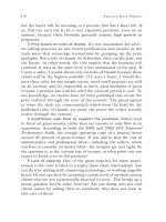
Figure 6.1. (a) Specimen shows the course of the phrenic nerve and the close anatomic relationship to other structures.
RB: right bronchus; RI: right inferior; RM: right middle; RPA: right pulmonary artery; RS: right superior pulmonary
veins; SCV: superior vena cava. (Source: Ho SY, Cabrera JA, Sanchez-Quintana D, 201211. Reproduced with permission
from Wolters Kluwer Health). (b) Histological sections through the RSPV and (c) the inferior pulmonary vein
respectively. The right phrenic nerve (surrounded by dots) is adherent to the fibrous pericardium (thin red-green line).
The broken lines indicate the pulmonary venous orifices. Note the myocardial sleeve (red) on the outer side of the
RSPV. ICV: inferior vena cava; PA: pulmonary artery; RIPV: right inferior pulmonary vein; RSPV: right superior
pulmonary vein; SCV: superior caval vein. (Masson’s trichrome stain.) (Source: Sanchez-Quintana D, Cabrera JA,
Climent V, Farre J, Weiglein A, Ho SY, 200512. Reproduced with permission from John Wiley and Sons Ltd).
the diaphragm. Histologic examination of the
transverse sections revealed that the phrenic nerve
is, on average, located closer to the RSPV
(2.1 ± 0.4 mm) than to the RIPV (3.2 ± 0.9 mm)
(Figure 6.1).12 The close proximity of the phrenic
nerve to the RSPV renders it more vulnerable to
injury during cryoballoon ablation of the RSPV
then during ablation of the RIPV.
Mechanisms of phrenic nerve injury
The mechanisms of PNI during cryoballoon application are presumably multifactorial (Table 6.1).
The mechanisms of cellular damage that are secondary to the cryoenergy application include ice
crystal formation in the extracellular space, resulting in a hyperosmotic milieu in extravascular spaces
that draws water from the cell, causing intracellular
desiccation. As the temperature decreases, the
extracellular crystals increase in number and cause
mechanical damage to the cell membrane and
organs. As the freezing continues, the intracellular
crystals can form and cause further harm to the
cell. A delayed direct cell injury may result from
apoptosis, inflammation, coagulation necrosis of
Table 6.1. Mechanisms of phrenic nerve injury
Proximity of the phrenic nerve (PN) to the
pulmonary vein (PV)
Distortion of the PV geometry by the balloon
inflation
Excessive temperature
Duration of the freeze
Repetitive freeze-thaw cycle
Vasoconstriction, thrombosis, and ischemia caused
by hypothermia
Previous injury to the nerve
the cell, and replacement fibrosis.13,14 Vascular
responses to cold temperature include vasoconstriction causing ischemia and circulatory stasis, which
has also been shown to play an important role in
cellular damage during cryotherapy.
The distance between the cryoballoon and the
phrenic nerve plays an important role in the degree
of damage to the nerve. The tissue is cooled with
outward expansion in a concentric fashion from the
cryoballoon surface touching the cardiac tissue.15
The closer the phrenic nerve is to the atrial tissue
Phrenic Nerve Palsy Prevention 69
adjoining the cryoballoon surface, the colder the
temperatures are near the nerve, making nerve
damage more likely. Okumura et al. showed in 10
dogs that balloon inflation at the PV orifice alters
the geometry of the native RSPV endocardial
surface and reduces the distance between the
balloon and the phrenic nerve.16 The inflated
balloon surface extended outside the diameter of
the original PV distortion is 5.6 ± 3.7 mm anteriorly
and 2.7 ± 3.5 mm posteriorly. Furthermore, prominent distortions of the RSPV and the RSPV orifice
moved the anatomic position of the phrenic nerve
on average by 4.3 ± 2.9 mm in the anterior to lateral
directions. The degree of anatomic distortion is
amplified when the balloon is pushed slightly into
the PV to minimize leaks.
The temperature achieved during a freeze and
the duration of cryoapplication can make a significant difference in the incidence of PNI and the
recovery of the nerve function. Colder temperatures
achieved during the freeze expand the cold front
further into the tissue, creating a deeper lesion and
increasing the chance of reaching detrimental temperatures near the phrenic nerve. Assuming that
the balloon has good contact with the tissue at
−30 °C and remains in contact for several minutes,
the 0 °C isotherm will be located 3 mm deep. If the
temperature, however, decreases to −90 °C, the isotherm will be roughly 1.4 cm deep.17 Exposure to
freezing temperatures can induce responses in the
tissues that vary from inflammation during minor
cold injury to tissue destruction during greater
cold injury.14 Based on previous research, peripheral nerves lose function when exposed to a temperature of 0 to −5 °C. The function returns when
the temperature rises if the sheath is intact.18,19
Fast freezing of tissue occurs only very close to the
balloon. Most of the frozen volume of tissue experiences slow cooling, which is not as lethal to cells as
fast cooling. Colder temperatures may be achieved
when the cryoballoon is advanced deeper into the
PV. Therefore, it is imperative to position the balloon
as antral as possible. As the duration of the cryoablation is extended, the size of the lesion continues
to expand and the affected area becomes larger.
Animals that were randomized to longer application duration demonstrated a higher degree of cell
destruction and fibrotic content.20 Lesion size continues to expand during the cryoablation application, which can last up to 2–3 minutes.15 Beazley
and colleagues showed that the length of the nerve
regeneration period or the duration of the nerve
palsy is predictable based on the distance between
the site of the cryolesion and the nerve and the
duration in which the nerve is exposed to cryoenergy.21 Therefore, if the application of cryoenergy is
stopped early enough to prevent prolonged exposure of the phrenic nerve to lethal temperatures,
the injury to the nerve can be reversed.
Other mechanisms of PNI include vasoconstriction and decreased blood flow induced by hypothermia. The decrease in blood supply to the nerve can
intensify the injury.22–25 Also, a repetitive freezethaw cycle can be more destructive to the tissue, as
the conduction of the cold front through the tissue
is faster with repeated freezing and larger crystals
may result from the fusion of previously formed
crystals.22,26 When tissue cooling is faster and the
volume of cellular necrosis increases, the PV can be
injured more rapidly.14 Furthermore, a phrenic
nerve with previously compromised functioning
(either mechanically from previous ablations or
surgery or from neurological diseases such as
myasthenia gravis or Guillain–Barré syndrome) is
at an increased risk for further injury by any of the
mechanisms described here.27 In these cases, special
attention needs to be given and precautions need to
be taken during the ablation to prevent further
injury to the nerve.
Pacing the phrenic nerve
Currently, there is no reliable method that can
predict PNI prior to the procedure. To prevent permanent PNP, it is essential to continuously monitor
phrenic nerve function during the cryoenergy
application in both the right superior and right inferior pulmonary veins. The phrenic nerve function is
monitored by advancing a pacing catheter into the
SVC, capturing the phrenic nerve above the level of
the cryoballoon, and monitoring the intensity of
the diaphragmatic excursions (Figure 6.2). The best
site at which to capture the phrenic nerve is in the
anterior-lateral portion of the SVC near the atrial–
SVC junction because at that location, the phrenic
nerve is separated from the SVC wall by only the
pericardium.
It is imperative that short-acting paralytics are
administered only during the induction of general
70 Catheter Cryoablation for Cardiac Arrhythmias
(a)
(b)
(c)
(d)
Figure 6.2. Position of different catheters in the superior vena cava (SVC) to facilitate capture of the phrenic nerve.
(a) Deflectable octapolar catheter (Biosense Webster Inc., CA, United States) located on the lateral wall of the SVC.
Notice that the phrenic nerve is captured above the cryoballoon. (b) Deflectable decapolar catheter (Biosense Webster
Inc.) prolapsed into the SVC. Notice the retroflexed curve for better stability. (c) Lasso Circular Mapping Catheter
(Biosense Webster Inc.) and a more distal portion of the decapolar catheter advanced distal in the SVC (d) for stable
phrenic nerve capture.
anesthesia in order to allow adequate time for the
paralytic effect to abate prior to ablation of the rightsided PV. A paralytic effect can hinder accurate
monitoring of the phrenic nerve function, delay
cryoablation of the right-sided vein, and mask PNP
during the ablation. If the paralytic effect lingers,
neostigmine may be used as a reversal agent.
Different catheters might be used to pace the
phrenic nerve (Figure 6.2). However, the stability
of the catheter and the reliable capture of the
phrenic nerve are essential during pacing. A sudden
loss of capture due to catheter movement may
mimic PNI. Conversely, the operator may be misled
by loss of capture if he or she assumes the catheter
was displaced, but in reality PNI had occurred. The
failure to recognize PNI can delay termination of
the ablation and cause permanent phrenic nerve
damage. A deflectable His catheter or coronary
Phrenic Nerve Palsy Prevention 71
sinus catheter can provide satisfactory stability and
pacing. Prolapsing the coronary sinus catheter into
the SVC and retroflexing the tip can help stabilize
the catheter and facilitate pacing (Figure 6.2). A
circular mapping catheter (Lasso, Biosense Webster
Inc., CA, USA) advanced into the SVC may provide
excellent stability and capture; however, it requires
a long sheath and adds extra cost. The closer the
phrenic nerve is captured near the cryoballoon, the
higher the chance of PNI. However, capturing the
phrenic nerve at a further distance from the balloon
does not eliminate the chance of PNI. Prior to
ablation, it is helpful to obtain a phrenic nerve
pacing threshold. The stimulation of the phrenic
nerve should be carried out at twice the pacing
threshold. A high current strength can potentially
overcome early nerve injury and conceal damage
to the nerve.28 The phrenic nerve should be paced
at an interval between 40 and 60 bpm. A slower
pacing rate can delay the detection of PNP, and
a rapid pacing rate can prematurely fatigue the
diaphragm.29
Monitoring of the phrenic nerve function
Fluoroscopy and palpation
During the cryoenergy application, multiple modalities are currently utilized to monitor phrenic nerve
function while pacing the nerve from the SVC (Table
6.2). Continued or intermittent fluoroscopy of the
right diaphragm during phrenic nerve pacing can
accurately diagnose the decrease in phrenic nerve
Table 6.2. Comparison of different strategies for monitoring phrenic nerve palsy during cryoballoon ablation
Method
Description
Advantages
Disadvantages
Fluoroscopy
Direct visualization of
diaphragmatic motion with
fluoroscopy
• Additional radiation
exposure to the patient
and the operator
• Does not predict phrenic
nerve injury (PNI)
Palpation
Palpation of diaphragmatic
excursion
• A sensitive method for
monitoring diaphragmatic
motion
• Used to evaluate reliable
phrenic nerve capture prior
to cryoablation
• Reliable and simple to apply
method for monitoring
diaphragmatic motion
Electromyography
Recording of diaphragmatic
compound motor action
potential (CMAP) by two
standard surface electrodes
positioned across the
diaphragm
• Earliest detection of
phrenic nerve injury
• The method is simple and
easily applicable.
• The only technique that
may predict PNI
Auditory
cardiotocograph
Decrescendo pitch on fetal
heart monitor (placed across
patient’s chest to detect
diaphragmatic contractions)
Direct visualization of
strength of diaphragmatic
excursion
Direct monitoring of the CO2
concentration in the
respiratory gases and plotting
a waveform of the expiratory
CO2 against time
• An auditory cue to the
operator
• May alert operator of PNI
prior to palsy
• Less radiation exposure to
the patient and the
operator
• Used as an adjunctive
technique to monitor
phrenic nerve function
Intracardiac
echocardiogram
(ICE)
Capnography
• Requires extra staff
member
• The strength of
diaphragmatic excursion
may change with
respiration
• CMAP signals might be
susceptible to respiratory
variations.
• The baseline amplitude
must be adequate.
• Affected by paralytic
agents
• Extra equipment placed
in the lab
• May be difficult to record
in obese patients
• Requires additional
venous access and the
intracardiac ultrasound
• Provides only indirect
evidence of phrenic nerve
function
72 Catheter Cryoablation for Cardiac Arrhythmias
function by observing the diminished diaphragmatic excursion. Although this method provides
direct visualization of the diaphragmatic motion, it
also exposes the patient and operator to additional
radiation and, because of this, is the least used
approach. Another technique utilized to monitor
phrenic nerve function is palpation of the diaphragmatic excursion during phrenic nerve pacing.
During phrenic nerve pacing, diaphragmatic contractions are sensed by placing the hand over the
right diaphragm and below the costal margin and
palpating every excursion. Weakening of the diaphragmatic contraction can indicate PNI. This
method is easily applicable, but the strength of the
diaphragmatic contraction can vary with respiration, which can misleadingly indicate PNI.
Intracardiac echocardiography and
fetal heart monitoring
Intracardiac echocardiography (ICE) may be utilized to continuously visualize the motion of the
liver with its capsule and indirectly image the contraction of the diaphragm during phrenic nerve
pacing.30 The ICE transducer (AcuNav, Acuson
Siemens Corp., CA, United States) is positioned at
the level of the diaphragm and pointed at the liver
(Figure 6.3). The decrease in intensity of liver movement from the diaphragmatic excursion can be
(a)
(b)
(c)
(d)
Figure 6.3. Intracardiac echocardiographic images of the diaphragm and the liver during phrenic nerve pacing
showing the diaphragm (a) relaxing and (b) contracting. (c) Fluoroscopy image showing position of intracardiac
echocardiography catheter (arrow) at the level of diaphragm. (Source: Lakhani M, Saiful F, Bekheit S, Kowalski M,
201230. Reproduced with permission from John Wiley and Sons Ltd). (d) Pulse Doppler of the liver motion during
phrenic nerve pacing. Notice the change in the amplitude of the velocity due to respiratory variation (private
communication from Dr. Raman Mitra).
Phrenic Nerve Palsy Prevention 73
easily observed and can correlate with PNP (Figure
6.3).30 If the entire liver cannot be easily visualized,
a pulse wave Doppler can be placed on the liver to
observe the liver exertions as a Doppler waveform.
A decrease in Doppler amplitude can indicate PNP
(Figure 6.3). ICE is an easily applicable tool for continuous direct diaphragmatic visualization without
the use of fluoroscopy, thereby significantly minimizing radiation to both the patient and the
operator.
Another method to monitor for PNI is to place an
external Doppler fetal heart monitor at the right
costal margin and listen for a change in pitch of the
diaphragmatic contraction. A fetal heart monitor
uses the Doppler effect to provide an audible simulation of diaphragmatic contractions. As the strength
of the diaphragmatic contraction decreases during
phrenic nerve pacing, an easily recognizable change
in pitch can be perceived. The fetal heart monitor
can provide an auditory cue to the physician and
staff of possible PNI, detectable even in a busy lab
(Audio Clip 6.1).
Diaphragmatic compound motor action
potential
A method found to detect the earliest changes to
phrenic nerve function induced by cryoballoon
ablation is diaphragmatic electromyography (EMG).
During phrenic nerve pacing, a reproducible
supramaximal diaphragmatic compound motor
action potential (CMAP) can be reliably recorded,
providing valuable information about phrenic
nerve function. The initial description of electrical
activity of the diaphragm by surface electrodes over
the lower intercostal spaces was made by Davis in
1967 in both healthy patients and those with
peripheral neuropathy.31 The location of the electrode yielding the largest diaphragm CMAP amplitude was 5 cm superior to the xiphoid and 16 cm
from the xiphoid along the right costal margin.32
The CMAP recordings of the phrenic nerve provided useful information on phrenic nerve function
in patients with neuromuscular disorders that
affect phrenic nerve conduction, especially in the
intensive care unit for patients who are difficult to
wean from the ventilator.33,34
The CMAP is a polyphasic signal composed
of four intervals: onset latency, peak latency, dura-
a b
a. Initial Latency
d
b. Peak Latency
c. Duration
d. Amplitude
c
1000
Figure 6.4. A polyphasic compound motor action
potential (CMAP) recorded at a sweep speed of
200 mm/s speed was magnified to demonstrate the
following intervals: (a) onset latency, (b) peak latency,
(c) duration, and (d) amplitude. (Source: Franceschi F,
Dubuc M, Guerra PG et al, 201135. Reproduced with
permission from Elsevier, Copyright © 2011 Elsevier).
tion, and amplitude (Figure 6.4).31,35 Franceschi et
al. examined the feasibility of recording diaphragmatic CMAPs during cryoballoon ablation and
defined characteristic CMAP changes that herald
phrenic nerve paralysis in the canine model.35 In
16 canines, a 6-F steerable decapolar catheter
(Livewire, St. Jude Medical, MN, United States) with
electrodes spaced 5 mm apart was placed in the
distal esophagus to record CMAPs. Cryoablation
was performed with a 23 mm cryoballoon during
phrenic nerve pacing at a site most likely to result
in PNI. The study found that reduction of the CMAP
amplitude was the earliest indication of PNI (Figure
6.5). At the time of earliest reduction in diaphragmatic excursion by fluoroscopy, the CMAP amplitude decreased by 48.1% ± 15.4%. In comparison,
the maximum reduction in CMAP amplitude produced by cryoballoon applications not associated
with a reduction in diaphragmatic excursion was
15.1% ± 12.1% (P < 0.0001). A 30% reduction in
CMAP amplitude yielded the best discriminatory
profile in predicting impaired diaphragmatic excursion with a sensitivity of 94.7% and a specificity
of 87.5%. A 30% reduction in CMAP amplitude
occurred at a mean of 33 ± 21 seconds. The average
time interval from the 30% reduction in CMAP
amplitude preceded the first fluoroscopic evidence
of palsy by 6 sec and palpation by 31 sec. Another
74 Catheter Cryoablation for Cardiac Arrhythmias
700
600
400
300
200
100
0
Mean Amplitude (µV)
(b)
(c)
500
0
30
60
90 120 150 180 210 240
Time (seconds)
700
600
500
400
300
100
0
30
60
P = value (cm) < 0.0001
80
70
60
50
40
30
20
10
0
200
0
Reduction in Amplitude of CMAP (%)
Mean Amplitude (µV)
(a)
Normal
Diaphragmatic
Excursion
Decrease in
Diaphragmatic
Excursion
90 120 150 180 210 240
Time (seconds)
Figure 6.5. Amplitude of the phrenic compound motor action potential (CMAP) during a cryoballoon ablation that did
(a) and did not (b) result in hemidiaphragmatic paralysis. In (a), an exponential reduction in the amplitude of the
CMAP is noted during lesions that resulted in phrenic nerve paralysis, with the largest effect during the first minute. In
contrast, (b) portrays relatively stable CMAP amplitudes during cryoballoon ablation applications that did not result in
hemidiaphragmatic paralysis. (c) Boxplots of the reduction in CMAP amplitude that is associated with lesions that did
not result in a reduction in diaphragmatic excursion (left) compared with lesions that paralyzed the right phrenic nerve
at the time of first perceptible reduction in diaphragmatic motion (right). Lower and upper edges of the box indicate
lower and upper quartiles. The line in the box represents the median value. Lower and upper bars indicate the 10th
and 90th percentiles. (Source: Franceschi F, Dubuc M, Guerra PG et al, 201135. Reproduced with permission from
Elsevier, Copyright © 2011 Elsevier).
study randomized 32 canines to conventionally
monitor either phrenic nerve function during cryoballoon ablation of the RSPV or monitoring the
nerve with diaphragmatic CMAP and ceasing ablation upon a 30% decrease in CMAP amplitude.36
The early termination of cryoablation guided by
decrease in CMAP amplitude resulted in a lower
rate of acute clinical PNI and a trend toward greater
potential for recovery in the event of PNP. The
injury to the phrenic nerve might be axonal in
nature,36 which is consistent with previous work in
peripheral axonal neuropathy showing that a loss
in CMAP amplitude reflects a disruption in axonal
integrity. On the other hand, the slowing of conduction velocity or prolongation of latency implies
demyelination.28 Also, focal distal cooling has a
more pronounced effect on amplitude, and diffuse
cooling has a more profound effect on conduction
velocity.28
Franceschi et al. described the first clinical application of diaphragmatic CMAPs recorded with
surface electrodes to prevent cryoballoon ablation–
induced PNP.37 Cryoablation was interrupted with
forcible balloon deflation upon a 20% reduction in
CMAP amplitude, which is when diaphragmatic
excursion remained intact. A transient reduction in
hemidiaphragmatic motion ensued, which fully
recovered within a minute.
Lakhani et al. evaluated diaphragmatic CMAPs
that were recorded on modified lead I (Figure 6.6)
in 44 consecutive patients who underwent cryoballoon ablation.38 Lead I was modified by placing
(a)
(b)
(c)
Figure 6.6. (a) Recordings of the diaphragmatic compound motor action potential (CMAP) during pacing from the
coronary sinus (CS) catheter at 60 bpm located in the superior vena cava (SVC). The magnified CMAP recordings are
located in the upper left corner. Notice the normal sinus rhythm in the background dissociated from the pacing. (b) An
example of noncapturing of the phrenic nerve during pacing from SVC. (c) An example of intermittent phrenic nerve
capture during pacing from SVC. Unintentionally, the patient received a paralytic agent 10 min prior to pacing. Notice
the low amplitude of CMAP and one noncaptured beat (arrow). His: His bundle.
76 Catheter Cryoablation for Cardiac Arrhythmias
CMAP Amplitude (mV)
0.4
0.35
0.3
0.25
0.2
0.15
0.1
Patients without PNP
0.05
0
Patients with PNP
0
30
60 90 120 150 180 210 240
Ablation Time (sec)
Figure 6.8. A graph of CMAP amplitude recorded using
Figure 6.7. Configuration of surface electrodes to record
diaphragmatic compound motor action potential on
modified lead I. The right arm (RA) surface electrode is
placed 5 cm above the xiphoid, and the left arm (LA)
surface electrode is placed 16 cm from the xiphoid down
the costal margin.
the standard surface right-arm electrocardiogram
(ECG) electrode 5 cm above the xiphoid and the leftarm ECG electrode 16 cm along the right costal
margin (Figure 6.7). In the study, three (6.8%)
patients developed PNI during a total of 170 cryoballoon applications to 86 right-sided PVs. The
minimal average CMAP amplitude during the freeze
(0.31 ± 0.19 mV) did not significantly change in
patients without PNP from the initial average
CMAP amplitude (0.33 ± 0.2 mV) (P = 0.58).
However, in patients with PNP, there was a sharp
drop in the average CMAP amplitude from
0.22 ± 0.01 mV to 0.07 ± 0.01 mV (P < 0.001)
(Figure 6.8). A decrease of CMAP amplitude during
the cryoenergy application greater than 35% of
the initial amplitude predicted PNI, a threshold
that is consistent with prior results.38 The initial
CMAP amplitude prior to ablation was lower in
patients with PNP than in patients without PNP.
When comparing the initial CMAP amplitude
before the first and the second applications of the
cryoballoon in patients without PNP, the amplitude
decreased in almost 50% of patients, and the
decrease in amplitude was more evident in the
RSPV. The decreased CMAP amplitude prior to
the second freeze can indicate an initial injury
to the nerve, which is consistent with the freezethaw hypothesis of cryoinjury.17,26
modified lead I during cryoballoon ablation in patients
with and without phrenic nerve palsy (PNP). With sharp
reduction in the amplitude on the beginning of the
ablation. The results are comparable with the data
presented by [35]. (Source: Lakhani M, Saiful F, Goyal N,
Bekheit S, Kowalski M, 201238. Reproduced with
permission from Elsevier, Copyright © 2012 Elsevier).
Monitoring the phrenic nerve function using diaphragmatic CMAP can effectively decrease PNI. The
amplitude of CMAPs may be affected by respiration
or body habitués. Adjusting the electrode more
superiorly may help obtain a better signal in obese
patients as the viscera pushes up on the diaphragm
when the patient is lying supine.
Using capnography as an adjunctive tool for
monitoring phrenic nerve function
A capnogram directly monitors the concentration
of CO2 in the respiratory gases and plots a waveform
of the expiratory CO2 against time. Phrenic nerve
pacing causes an unnatural contraction of the diaphragm that translates into an interrupted pattern
of CO2 concentration (Figure 6.9). When the
phrenic nerve is injured, the pattern changes to a
conventional waveform associated with normal
inhalation and exhalation; as the right diaphragm
is not contracting, the left diaphragm continues to
assist in normal gas exchange. This method should
be used as an adjunctive technique to monitor
phrenic nerve function and not as a primary
method as it provides only indirect evidence of
phrenic nerve function.
Phrenic Nerve Palsy Prevention 77
Recommendations
PNI is a complication associated with cryoballoon
ablation that can be avoided with appropriate planning and monitoring (Table 6.3). It is vital to discuss
the importance of phrenic nerve monitoring with
the laboratory staff and anesthesiologist prior
to the beginning of the case. During the ablation
of the right-sided PVs, the laboratory staff should
be attentive to any signs of phrenic nerve dysfunction and trained to stop ablation immediately. If the
patient is intubated, the anesthesiologist must
Figure 6.9. On the left of the figure, a capnogram
waveform is shown during right phrenic nerve pacing.
Each notch during the plateau represents contraction of
the diaphragm. The arrow indicates development of
phrenic nerve palsy and the immediate change in
waveform to a normal breathing pattern.
know not to use any long-acting paralytic agents
during the case or administer extra doses of the
paralytic agents preceding ablation of the rightsided PV. A short-acting paralytic agent can be
administered at the beginning of the case to facilitate intubation as the effect of the agent will dissipate during the case before pacing of the phrenic
nerve is required.
Inflation of the balloon at the PV orifice distorts
the geometry of the native PV endocardial surface
and reduces the distance between the balloon surface
and the phrenic nerve, despite the absence of the
balloon’s migration into the vein.16 The degree of
anatomic distortion can also be amplified when the
balloon is pushed slightly into the PV to maximize
the occlusion. Reducing the distance between the
balloon and the phrenic nerve increases the chance
of injury to the nerve. Therefore, it is imperative to
inflate the balloon outside the PV and maintain the
balloon as antral as possible during the ablation to
prevent anatomic distortion of the PV orifice. PNI
may be more common with the use of the 23 mm
balloon, which results in more distal PV cryoablation. In early experiences with cryoballoons,
Table 6.3. Recommendations to prevent phrenic nerve injury
• Discuss the importance of phrenic nerve monitoring with the laboratory staff and anesthesiologist prior to the
beginning of the case.
• If patient had prior CABG or valve replacement, perform inhalation and exhalation chest x-ray to exclude left
diaphragm palsy. If left diaphragm palsy is present consider not to use cryoballoon to isolate the right PV as it
may cause bilateral phrenic nerve palsy.
• Avoid long-acting paralytic agents during cryoballoon ablation if patient is intubated as it will prevent pacing of
phrenic nerve and monitoring of its function.
• Inflate the balloon outside the pulmonary vein (PV) and maintain the balloon as antral as possible to prevent
anatomic distortion of the PV orifice.
• Monitor the rate of temperature descent as a steep descent can indicate distal locating of the balloon.
• Vigorously monitor the phrenic nerve function by pacing the phrenic nerve from the superior vena cava (SVC)
above the cryoballoon.
• Continuously pace the phrenic nerve from the SVC during ablation of both right superior pulmonary vein and
right inferior pulmonary vein.
The stimulation of the PN should be carried out at twice the pacing threshold.
• Monitor phrenic nerve function by measuring it, feeling it, hearing it, or seeing it.
Measure the change in diaphragmatic compound motor action potential (CMAP) amplitude. A 30% reduction
in CMAP amplitude yielded the most discriminatory cutoff value in predicting phrenic nerve injury.
Feel the excursion of the diaphragm by palpation.
Hear the change in tone of diaphragmatic excursion using a fetal heart monitor.
Visualize the motion of the liver and diaphragm by intracardiac echocardiography.
• Simultaneously employ the diaphragmatic CMAP amplitude and one or two other techniques to monitor phrenic
nerve function.
• Immediately stop ablation at any signs of phrenic nerve injury.
Immediate deflation of the balloon may be initiated by pressing the emergency deflation button on the console.
78 Catheter Cryoablation for Cardiac Arrhythmias
Nuemann et al. reported 26 phrenic nerve palsies out
of 346 patients (7.5%), 24 of which occurred when
using the 23 mm balloon.1 Injury to the right phrenic
nerve can be minimized by using only the 28 mm
cryoballoon;3 the intentionally oversized balloon
covers the proximal left atrial antrum region with as
much distance from the phrenic nerve as possible.12
Different signs or maneuvers may be utilized to successfully identify the suitable antral location of the
balloon. When the balloon is appropriately engaged
at the PV ostium (os), it takes the shape of an onion.
However, when the balloon is deep inside the vein,
both sides of the balloon become compressed,
making the balloon more tubular to resemble a
marshmallow (Figure 6.10). Some pulmonary
veins, especially the RSPV, are funnel shaped, making
the PV orifice potentially difficult to identify. To
ensure that the balloon is not deep inside the vein,
during contrast injection, the balloon can be slowly
withdrawn to the left atrium until the contrast dissipates from the vein outlining the PV os (see Video
Clip 6.1). This maneuver can outline the orifice of
the vein that has difficult geometry and prevent
balloon engagement deep inside the vein. Once the
PV os is identified, the balloon can be slightly
advanced forward and ablation can be initiated.
When the cryoballoon is inflated and engaged at the
(a)
PV os, an intracardiac echocardiogram can effectively identify the portion of the balloon located
outside the PV. To prevent ablation inside the PV, at
least 50% of the balloon’s circumference should be
visible outside the PV.
The rate of temperature descent and unusually
low maximal temperature (usually below −60 °C)
can prognosticate if the cryoballoon is located distal
inside the PV. If the slope of temperature descent is
very steep and the maximal temperature is reached
quickly into the freeze, it is prudent to stop ablation
and confirm if the balloon is not distal inside the PV.
See it, hear it, feel it, and measure it
Early detection of PNI and immediate termination
of ablation are essential in the prevention of PNP. It
is important to continuously monitor the phrenic
nerve function by pacing the phrenic nerve above
the cryoballoon during the ablation of both rightsided PVs. There is no reliable method to predict
PNI; however, implementing vigorous monitoring
of the nerve function can assure early detection and
prevent permanent PNI. Since decrease in the
CMAP amplitude is the earliest sign of detectable
injury to the nerve (and is simple and easily applicable), it should be used as the major technique for
(b)
Figure 6.10. (a) A distal and (b) proximal location of the cryoballoon inside the right superior pulmonary veins in the
same patient. Note that the balloon advanced distally inside the pulmonary vein takes a tubular shape, while a balloon
positioned more antrally remains spherical.
Phrenic Nerve Palsy Prevention 79
monitoring in conjunction with one or two other
methods. These methods include either palpation of
the diaphragmatic excursion or movement of liver
visualized on ICE or a fetal heart monitor. The
amplitude of CMAP may be monitored by adjusting
the caliper on the recording system 30% below the
initial CMAP amplitude, as this yielded the most
discriminatory cutoff value in predicting hemidiaphragmatic paralysis.35,36,38 Once the amplitude
decreases below the caliper line, ablation should be
immediately terminated. Monitoring of the diaphragmatic motion by fluoroscopy may be employed
to confirm phrenic nerve capture; however, due to
the potential radiation exposure, this is the least
favored method of monitoring phrenic nerve
function.
Early discontinuation of ablation and warming
of the tissue are vital in the prevention of permanent phrenic nerve damage. Reversible effects of
cryothermal ablation were examined previously
and are a function of temperature and duration.20,22,26,35,37 Shorten the time the cell is exposed
to a hypothermic insult and the warmer the temperature, the more rapidly the cell will recover.39,40
A delay may be expected between cessation of the
cryoapplication and the rewarming of the phrenic
nerve, since the balloon temperature must reach
+20 °C before the cryoballoon deflates. Prior to
complete balloon deflation, persistent occlusion of
the pulmonary vein may slow the rewarming
process and delay temperature rise. Therefore, an
immediate deflation of the balloon may be initiated
(a)
Figure 6.11. Inspiration chest X-rays
performed (a) before and (b) after
ablation. Patients suffered a right
phrenic nerve palsy during the
ablation as evident by an elevated
right hemidiaphragm. (Source:
Sacher F, Monahan KH, Thomas SP
et al, 20069. Reproduced with
permission from Elsevier, Copyright
© 2006 Elsevier).
by pressing an emergency deflation button on the
console to reestablish PV blood flow.
What to do when phrenic nerve injury
occurs
Once PNI is detected by the methods described in
this chapter, it is imperative to stop ablation immediately. Since the degree of the tissue injury is
dependent on the temperature and the amount of
time tissue is exposed to freezing temperatures, an
early termination of ablation may prevent further
damage and expedite recovery of the nerve function. If the injury to the phrenic nerve is recognized
early and the ablation is terminated, the majority of
the phrenic nerves recover in 12 months.1,2,4 Inhalation and exhalation chest X-rays can confirm PNI
after the procedure (Figure 6.11). The chest X-rays
can be repeated a few weeks later to follow the
phrenic nerve function if the patient continues to
have symptoms. Since the late phase of cryoinjury
involves inflammation,26 steroids can be administered after the injury is detected. However, evidence
does not exist to support this treatment.
Once injury to the nerve ensues during cryoballoon ablation, cryoenergy cannot be utilized to
ablate the remaining right-sided PV because the
phrenic nerve can no longer be monitored. Generally, by the time the PNI occurs, the PV is isolated
because the cryoenergy has penetrated the tissue of
the PV and completed the lesion. If the vein is not
isolated or there is a remaining right-sided PV after
(b)
80 Catheter Cryoablation for Cardiac Arrhythmias
PNP, the ablation ought to be completed using radiofrequency. Since PNI is more common during
cryoballoon ablation of the RSPV, it might be feasible to ablate the RIPV before the RSPV.
Summary
PNI is the most common complication associated
with circumferential ablation of the pulmonary
veins using cryoballoon catheters to treat atrial
fibrillation. The anatomic course of the phrenic
nerve in close proximity to the right-sided pulmonary veins deems the nerve more susceptible to
injury. The mechanism of the injury to the nerve is
multifactorial and includes temperature, duration
of the freezing, and anatomical distortion of the
geometry of the native pulmonary vein’s endocardial surface. There is no reliable method to predict
PNI. However, the pacing of the phrenic nerve from
the superior vena cava and vigorous monitoring of
the nerve’s integrity during cryoenergy application
can detect the earliest sign of injury to the nerve.
The decrease in diaphragmatic CMAP amplitude
can precede diaphragmatic paralysis, and it should
be used with one or two other methods to simultaneously monitor phrenic nerve function. The key to
prevention of PNP is early recognition of injury to
the nerve and immediate termination of ablation.
Interactive Case Studies related to this
chapter can be found at this book’s
companion website, at
www.chancryoablation.com
References
1. Neumann T, Vogt J, Schumacher B, et al. Circumferential pulmonary vein isolation with the cryoballoon
technique results from a prospective 3-center study. J
Am Coll Cardiol. 2008;52:273–8.
2. Kojodjojo P, O’Neill MD, Lim PB, et al. Pulmonary
venous isolation by antral ablation with a large cryoballoon for treatment of paroxysmal and persistent
atrial fibrillation: medium-term outcomes and nonrandomised comparison with pulmonary venous isolation by radiofrequency ablation. Heart. 2010;96:
1379–84.
3. Chun KR, Schmidt B, Metzner A, et al. The “single big
cryoballoon” technique for acute pulmonary vein iso-
lation in patients with paroxysmal atrial fibrillation:
a prospective observational single centre study. Eur
Heart J. 2009;30:699–709.
4. Van BY, Janse P, Rivero-Ayerza MJ, et al. Pulmonary
vein isolation using an occluding cryoballoon for circumferential ablation: feasibility, complications, and
short-term outcome. Eur Heart J. 2007;28:2231–7.
5. Packer DL, Iwin J. Cryoballoon ablation of pulmonary
veins for paroxysmal atrial fibrillation: first results of
the North American Arctic Front STOP-AF pivotal
trial. J Am Coll Cardiol. 2010;55:E3015–6.
6. Andrade JG, Khairy P, Guerra PG, et al. Efficacy and
safety of cryoballoon ablation for atrial fibrillation:
a systematic review of published studies. Heart
Rhythm. 2011;8:1444–51.
7. Packer DL, Kowal R, Wheelan K, et al. Impact of experience on efficacy and safety of cryoballoon ablation
for atrial fibrillation: outcomes of the STOP-AF continued access protocol. Heart Rhythm. 2011;8:S379.
8. Bunch TJ, Bruce GK, Mahapatra S, et al. Mechanisms
of phrenic nerve injury during radiofrequency ablation at the pulmonary vein orifice. J Cardiovasc Electrophysiol. 2005;16:1318–25.
9. Sacher F, Monahan KH, Thomas SP, et al. Phrenic
nerve injury after atrial fibrillation catheter ablation:
characterization and outcome in a multicenter study.
J Am Coll Cardiol. 2006;47:2498–503.
10. Bai R, Patel D, Di BL, et al. Phrenic nerve injury after
catheter ablation: should we worry about this complication? J Cardiovasc Electrophysiol. 2006;17:944–8.
11. Ho SY, Cabrera JA, Sanchez-Quintana D. Left atrial
anatomy revisited. Circ Arrhythm Electrophysiol.
2012;5:220–8.
12. Sanchez-Quintana D, Cabrera JA, Climent V, et al.
How close are the phrenic nerves to cardiac structures? Implications for cardiac interventionalists. J
Cardiovasc Electrophysiol. 2005;16:309–13.
13. Takamatsu H, Zawlodzka S. Contribution of extracellular ice formation and the solution effects to the
freezing injury of PC-3 cells suspended in NaCl solutions. Cryobiology. 2006;53:1–11.
14. Gage AA, Baust J. Mechanisms of tissue injury in
cryosurgery. Cryobiology. 1998;37:171–86.
15. Dubuc M, Roy D, Thibault B, et al. Transvenous catheter ice mapping and cryoablation of the atrioventricular node in dogs. Pacing Clin Electrophysiol.
1999;22:1488–98.
16. Okumura Y, Henz BD, Bunch TJ, et al. Distortion of
right superior pulmonary vein anatomy by balloon
catheters as a contributor to phrenic nerve injury. J
Cardiovasc Electrophysiol. 2009;20:1151–7.
17. The principles of cryobiology. In: Khairy P, Dubuc M,
editors. Cryoablation for cardiac arrhythmias. Montreal: Montreal Heart Institute; 2008. p. 13–21.
Phrenic Nerve Palsy Prevention 81
18. Whittaker DK. Mechanisms of tissue destruction following cryosurgery. Ann R Coll Surg Engl. 1984;66:
313–8.
19. Gaster RN, Davidson TM, Rand RW, et al. Comparison
of nerve regeneration rates following controlled freezing or crushing. Arch Surg. 1971;103:378–83.
20. Atienza F, Almendral J, Sanchez-Quintana D, et al.
Cryoablation time-dependent dose-response effect at
minimal temperatures (−80 degrees C): an experimental study. Europace. 2009;11:1538–45.
21. Beazley RM, Bagley DH, Ketcham AS. The effect of
cryosurgery on peripheral nerves. J Surg Res. 1974;
16:231–4.
22. Khairy P, Dubuc M. Transcatheter cryoablation part
I: preclinical experience. Pacing Clin Electrophysiol.
2008;31:112–20.
23. Rabb JM, Renaud ML, Brandt PA, et al. Effect of freezing and thawing on the microcirculation and capillary endothelium of the hamster cheek pouch.
Cryobiology. 1974;11:508–18.
24. Rothenborg HW. Cutaneous circulation in rabbits
and humans before, during, and after cryosurgical
procedures measured by xenon-133 clearance. Cryobiology. 1970;6:507–11.
25. Zacarian SA, Stone D, Clater M. Effects of cryogenic
temperatures on microcirculation in the golden
hamster cheek pouch. Cryobiology. 1970;7:27–39.
26. Gill W, Fraser J, Carter DC. Repeated freeze-thaw
cycles in cryosurgery. Nature. 1968;219:410–3.
27. Basiri K, Dashti M, Haeri E. Phrenic nerve CMAP
amplitude, duration, and latency could predict respiratory failure in Guillain-Barre syndrome. Neurosciences (Riyadh). 2012;17:57–60.
28. Gooch CL, Weimer LH. The electrodiagnosis of neuropathy: basic principles and common pitfalls. Neurol
Clin. 2007;25:1–28.
29. Glenn WW, Phelps ML. Diaphragm pacing by electrical stimulation of the phrenic nerve. Neurosurgery.
1985;17:974–84.
30. Lakhani M, Saiful F, Bekheit S, et al. Use of intracardiac echocardiography for early detection of phrenic
nerve injury during cryoballoon pulmonary vein isolation. J Cardiovasc Electrophysiol. 2012;23:874–6.
31. Davis JN. Phrenic nerve conduction in man. J Neurol
Neurosurg Psychiatry. 1967;30:420–6.
32. Dionne A, Parkes A, Engler B, et al. Determination of
the best electrode position for recording of the diaphragm compound muscle action potential. Muscle
Nerve. 2009;40:37–41.
33. Bolton CF. Neuromuscular abnormalities in critically
ill patients. Intensive Care Med. 1993;19:309–10.
34. Zifko UA, Zipko HT, Bolton CF. Clinical and electrophysiological findings in critical illness polyneuropathy. J Neurol Sci. 1998;159:186–93.
35. Franceschi F, Dubuc M, Guerra PG, et al. Diaphragmatic electromyography during cryoballoon ablation:
a novel concept in the prevention of phrenic nerve
palsy. Heart Rhythm. 2011;8:885–91.
36. Andrade JG, Dubuc M, Guerra PG, et al. Comparison
between standard monitoring and diaphragmatic electromyography for the prevention of phrenic nerve palsy
during pulmonary vein isolation with a novel cryoballoon catheter. Heart Rhythm. 2012;9:S321–42.
37. Franceschi F, Dubuc M, Guerra PG, et al. Phrenic
nerve monitoring with diaphragmatic electromyography during cryoballoon ablation for atrial fibrillation:
the first human application. Heart Rhythm. 2011;8:
1068–71.
38. Lakhani M, Saiful F, Goyal N, et al. Recording of diaphragmatic electromyograms during cryoballoon
ablation for atrial fibrillation can accurately predict
phrenic nerve palsy. Heart Rhythm. 2012;9:S387.
39. Lister JW, Hoffman BF, Kavaler F. Reversible cold block
of the specialized cardiac tissues of the unanaesthetized dog. Science. 1964;145:723–5.
40. Lemola K, Dubuc M, Khairy P. Transcatheter cryoablation part II: clinical utility. Pacing Clin Electrophysiol. 2008;31:235–44.
C H APTER 7
Linear Isthmus Ablation for Atrial Flutter:
Catheter Cryoablation versus
Radiofrequency Catheter Ablation
Gregory K. Feld and Navinder Sawhney
University of California, San Diego, CA and Sulpizio Family Cardiovascular Center, La Jolla, CA, USA
Introduction
Typical (and reverse typical) atrial flutter (AFL) may
cause severe symptoms or serious complications,
including stroke, myocardial infarction, and occasionally a tachycardia-induced cardiomyopathy. In
addition, AFL is often medically refractory. Since the
electrophysiologic substrate underlying AFL is now
well established, and in view of its relative pharmacological resistance, catheter ablation has emerged
as a safe and effective first-line treatment. While
radiofrequency catheter ablation (RFCA) of AFL has
a relatively high long-term success rate (>95%), it
can cause complications, including cardiac perforation and tamponade, and it is associated with significant pain during ablation. Catheter cryoablation
may therefore have some inherent advantages over
RFCA for ablation of AFL. This chapter will review
the role of RFCA versus catheter cryoablation for
treatment of typical (and reverse typical) AFL.
Atrial flutter terminology
Due to the varied terminology used to describe
human AFL in the past, the Working Group of
Arrhythmias of the European Society of Cardiology
and the North American Society of Pacing and
Electrophysiology (now the Heart Rhythm Society)
published a consensus document in 2001 to standardize terminology for AFL.1 The terminology recommended by this working group to describe
cavo-tricuspid isthmus (CTI)-dependent AFL, with
either a counterclockwise or clockwise direction
around the tricuspid valve annulus, is typical and
reverse typical AFL, respectively.1
Pathophysiologic mechanisms of AFL
Typical and reverse typical AFL (Figure 7.1a and
7.1b) have been shown to be due to macro-reentry,
in either a counterclockwise (typical) or clockwise
(reverse typical) direction around the tricuspid
valve annulus.2–7 Slow conduction has been shown
to be present in the CTI, accounting for one-third to
one-half of the AFL cycle length.8–10 The CTI is anatomically bounded by the inferior vena cava and
Eustachian ridge posteriorly and the tricuspid valve
annulus anteriorly, which form lines of conduction
block or barriers delineating a protected zone in the
reentry circuit.5,11–13 The path of the reentrant
circuit outside the confines of the CTI consists of a
The Practice of Catheter Cryoablation for Cardiac Arrhythmias, First Edition. Edited by Ngai‑Yin Chan.
© 2014 John Wiley & Sons, Ltd. Published 2014 by John Wiley & Sons, Ltd.
82
Linear Isthmus Ablation for Atrial Flutter 83
(a)
(b)
Figure 7.1. Schematic diagrams demonstrating the activation patterns in the typical (a) and reverse typical (b) forms of
human type 1 atrial flutter (AFL), as viewed from below the tricuspid valve annulus looking up into the right atrium.
In the typical form of AFL, the reentrant wavefront rotates counterclockwise in the right atrium, whereas in the
reverse typical form reentry is clockwise. Note that the Eustachian ridge (ER) and crista terminalis (CT) form lines of
block, and that an area of slow conduction (wavy line) is present in the isthmus between the inferior vena cava (IVC)
and Eustachian ridge and the tricuspid valve annulus. CS: coronary sinus ostium, His: His bundle, SVC: superior vena
cava. (Source: Adapted from Feld GK, Srivatsa U, Hoppe B, 200652. Reproduced with permission from Elsevier,
Copyright © 2006, Elsevier).
broad activation wavefront in the interatrial septum
and right atrial free wall around the crista terminalis and the tricuspid valve annulus.11–14
Slow conduction in the CTI may be caused by
anisotropic fiber orientation,2 8–10,15,16 which may
also predispose to the development of unidirectional block in the CTI and account for the observation that typical AFL is more likely to be induced
when pacing from the coronary sinus ostium, and
conversely reverse typical AFL is more likely to be
induced when pacing from the low lateral right
atrium.17–19 The predominant clinical presentation
is typical AFL, likely because the triggers commonly
arise from the left atrium in the form of premature
atrial contractions or nonsustained atrial fibrillation,20 which conduct into the CTI medially, resulting in clockwise unidirectional block and resultant
initiation of typical AFL.
7.2a). In contrast, in reverse typical AFL the F wave
pattern is less specific, with a sine wave pattern in
the inferior ECG leads (Figure 7.2b). However, since
typical and reverse typical AFL utilize the same
reentry circuit, just in opposite directions, their
rates are usually similar. The determinants of the F
wave pattern on ECG are dependent on activation
of the left atrium, with the inverted F waves in
typical AFL resulting from activation of the left
atrium initially via the coronary sinus, and the
upright F waves in reverse typical AFL resulting
from activation of the left atrium initially via Bachman’s bundle.21,22 Following extensive left atrial
ablation for AF, the F wave pattern in typical AFL
may be significantly different from the characteristic saw-tooth pattern, due to the reduction in left
atrial voltage after ablation and the change in activation pattern.23
Electrocardiogram diagnosis of AFL
Mapping of AFL
The surface 12-lead electrocardiogram (ECG) in
typical AFL is usually diagnostic with an inverted
saw-tooth F wave pattern in the inferior ECG leads
II, III, and aVF; low-amplitude biphasic F waves in
leads I and aVL; an upright F wave in precordial
lead V1; and an inverted F wave in lead V6 (Figure
Despite the utility of the 12-lead ECG in diagnosing
AFL, an electrophysiologic study utilizing mapping
and entrainment should be done to confirm the
underlying mechanism, if catheter ablation is to
be successful. This is particularly true for reverse
typical AFL, which is more difficult to diagnose
(a)
I
aVR
v1
v4
II
aVL
v2
v5
III
aVF
v3
v6
I
aVR
V1
V4
II
aVL
V2
V5
III
aVF
V3
V6
(b)
Figure 7.2. (a) 12-lead electrocardiogram recorded from a patient with typical atrial flutter (AFL). Note the typical
saw-toothed pattern of inverted F waves in the inferior leads II, III, aVF. Typical AFL is also characterized by flat to
biphasic F waves in I and aVL, respectively; an upright F wave in V1; and an inverted F wave in V6. (b) 12-lead
electrocardiogram recorded from a patient with reverse typical AFL. The F wave in the reverse typical form of AFL has
a less distinct sine wave pattern in the inferior leads. In this case, the F waves are upright in the inferior leads II, III, and
aVF; biphasic in leads I, aVL, and V1; and upright in V6. (Source: Adapted from Feld GK, Srivvatsa U, Hoppe B, 200652.
Reproduced with permission from Elsevier, Copyright © 2006 Elsevier).
Linear Isthmus Ablation for Atrial Flutter 85
HALO
CS
HIS
HIS
HALO
CS
RF
RF
RV
RV
LAO
RAO
Figure 7.3. Left anterior oblique (LAO) and right anterior oblique (RAO) fluoroscopic projections showing the
intracardiac positions of the right ventricular (RV), His bundle (HIS), coronary sinus (CS), Halo (HALO), and mapping
and ablation catheter (RF). Note that the Halo catheter is positioned around the tricuspid valve annulus with the
proximal electrode pair at the 1:00 o’clock position and the distal electrode pair at the 7:00 o’clock position in the LAO
view. The mapping and ablation catheter is positioned in the sub-Eustachian isthmus, midway between the interatrial
septum and low lateral right atrium, with the distal 8 mm ablation electrode near the tricuspid valve annulus. (Source:
Adapted from Feld GK, Srivatsa U, Hoppe B, 200652. Reproduced with permission from Elsevier, Copyright © 2006
Elsevier).
on ECG. For standard catheter mapping, multielectrode catheters are positioned in the right
atrium, His bundle region, and coronary sinus. To
determine the endocardial activation sequence, a
multipolar electrode-mapping catheter (e.g., HaloTM
manufactured by Cordis-Webster, Inc., CA, United
States) is commonly positioned in the right atrium
around the tricuspid valve annulus (Figure 7.3).
Recordings are then obtained from all electrodes
during spontaneous or pacing-induced AFL and
analyzed to determine right atrial activation
sequence.17,18 Typical and reverse typical AFL are
characterized by a counterclockwise or clockwise
activation pattern in the right atrium around the
tricuspid valve annulus, respectively (Figure 7.4a
and 7.4b), and demonstration of concealed entrainment during pacing from the CTI (Figure 7.5a
and 7.5b) confirms the isthmus dependence of the
reentry circuit.5 Three-dimensional electroanatomical mapping may also be performed to diagnose
and confirm the underlying mechanism of AFL, but
it is not required for a successful outcome of ablation in most cases.
Radiofrequency catheter ablation of AFL
Catheter ablation of typical AFL has been performed most commonly with a steerable radio
frequency ablation catheter.3,5–7,24–26 Although a
variety of ablation catheters are currently available, we prefer to use a large-curve catheter, with a
preshaped or steerable guiding sheath in order to
ensure that the ablation electrode will reach the
tricuspid valve annulus with good tissue contact.
Catheters with either saline-cooled ablation electrodes or large distal ablation electrodes (i.e.,
8–10 mm) are preferred. During ablation with
saline-cooled catheters, a maximum power of
35–50 W and temperatures of 42–45 °C should be
used initially, as powers above 50 W may lead to
steam pops.27–30 In contrast, large-tip (i.e., 8–10 mm)
ablation catheters may require up to 100 W of
power to achieve target temperatures of 50–70 °C,
due to the greater energy-dispersive effects of the
larger ablation electrode.29,31–33
The preferred target for ablation of typical AFL
is the CTI.3,5–7,24–30,32,33 The ablation catheter is
86 Catheter Cryoablation for Cardiac Arrhythmias
(a)
(b)
Linear Isthmus Ablation for Atrial Flutter 87
Figure 7.4. Endocardial electrograms from the mapping and ablation, Halo, CS, and His bundle catheters, and surface
electrocardiogram (ECG) leads I and aVF, demonstrating (a) a counterclockwise (CCW) rotation of activation in the
right atrium in a patient with typical atrial flutter (AFL), and (b) a clockwise (CW) rotation of activation in the right
atrium in a patient with reverse typical AFL. The AFL cycle length was 256 msec for both CCW and CW forms. Arrows
demonstrate the activation sequence. Halo D–Halo P tracings are 10 bipolar electrograms recorded from the distal (low
lateral right atrium) to proximal (high right atrium) poles of the 20-pole Halo catheter positioned around the tricuspid
valve annulus with the proximal electrode pair at the 1:00 o’clock position and the distal electrode pair at the 7:00
o’clock position. CSP: electrograms recorded from the coronary sinus catheter proximal electrode pair positioned at the
ostium of the coronary sinus; HISP: electrograms recorded from the proximal electrode pair of the His bundle catheter;
RF: electrograms recorded from the mapping and ablation catheter positioned with the distal electrode pair in the
cavo-tricuspid isthmus. (Source: Adapted from Feld GK, Srivatsa U, Hoppe B, 200652. Reproduced with permission from
Elsevier, Copyright © 2006 Elsevier).
positioned fluoroscopically (Figure 7.3) across the
CTI, with the distal ablation electrode near the tricuspid valve annulus in the right anterior oblique
view, and midway between the septum and low
right atrial free wall (in the 6 or 7 o’clock position)
in the left anterior oblique (LAO) view. When appropriately positioned, the distal ablation electrode
records an atrial-to-ventricular electrogram amplitude ratio of 1 : 2 to 1 : 4 (Figure 7.4a). For RFCA,
the ablation catheter is gradually withdrawn a
few millimeters at a time across the entire CTI,
pausing for 30–60 seconds at each location, during
a continuous or interrupted energy application.
RFCA of the CTI may require several sequential
30–60 sec energy applications during a stepwise
catheter pullback, or a prolonged energy application of up to 120 sec or more during a continuous
catheter pullback. Radiofrequency energy application should be immediately interrupted when the
catheter has reached the inferior vena cava, since
ablation in the venous structures is known to cause
significant pain.
Procedure endpoints for ablation of AFL
Ablation may be performed during AFL or sinus
rhythm. If ablation is performed during AFL, the
first endpoint is its termination (Figure 7.6). Despite
termination of AFL, however, CTI conduction commonly persists. Following ablation, electrophysiologic testing should be performed by pacing at a
cycle length of 600 msec (or greater, depending on
the sinus cycle length) to determine if there is bidirectional CTI conduction block (Figures 7.7 and
7.8). Bidirectional CTI conduction block is confirmed by demonstrating a strictly cranial-to-caudal
activation sequence in the contralateral right
atrium during pacing from the coronary sinus
ostium or low lateral right atrium, respectively,34–36
and recording widely spaced double potentials
(≥100 msec apart) along the ablation line during
pacing lateral or medial to the line (Figure 7.9).37,38
The presence of bidirectional CTI conduction block
after ablation is associated with a significantly lower
recurrence rate of AFL during long-term followup.34–36,39 Pacing should be repeated at least 30–
60 min after ablation to ensure that bidirectional
CTI block persists, and burst pacing should be performed to ensure that AFL cannot be reinduced
after ablation.3,5–7,24–28,30–33,40 If CTI block is not
achieved with either an 8–10 mm tip electrode
catheter or a cooled-tip ablation catheter, crossing
over to the alternative catheter or another energy
source may be successful.41
Outcomes of radiofrequency catheter
ablation of typical AFL
Early reports3–6 on AFL ablation revealed recurrence rates up to 20–45% (Table 7.1). However,
more contemporary studies have demonstrated
acute and chronic success rates in excess of 95%.
These improved results have been attributed to confirmation of bidirectional CTI conduction block as
an endpoint for successful ablation of AFL.24–33
Patients with difficult CTI anatomy due to a pouch
or longer isthmus may have a higher incidence of
recurrent CTI conduction in long-term follow-up.42
88 Catheter Cryoablation for Cardiac Arrhythmias
(a)
(b)
Linear Isthmus Ablation for Atrial Flutter 89
Figure 7.5. Endocardial electrograms from the RF, Halo, CS, and His bundle catheters, and surface ECG leads I, aVF, and
V1, are shown, demonstrating concealed entrainment from an RF ablation catheter positioned in the cavo-tricuspid
isthmus (CTI) in a patient with (a) typical AFL and (b) reverse typical AFL. Note that the tachycardia is accelerated to
the pacing cycle length, the tachycardia continues upon termination of pacing, the first postpacing interval and the
tachycardia cycle length are equal (284 vs. 284 and 266 vs. 266 msec) , the stimulus to proximal CS electrogram time
and the local electrogram on the RF catheter to proximal CS electrogram time are the same (58 vs. 58 and 200 vs. 200
msec), and there is no change in activation sequence, endocardial electrograms, or surface P wave morphology. Halo
D–Halo P are 10 bipolar electrograms recorded from the distal (low lateral right atrium) to proximal (high right
atrium) poles of the 20-pole Halo catheter positioned around the tricuspid valve annulus with the proximal electrode
pair at the 1 o’clock position and the distal electrode pair at the 7 o’clock position. CSP-D: electrograms recorded from
the coronary sinus catheter proximal to distal electrode pairs, with the proximal pair positioned at the ostium of the
coronary sinus; HISP&D: electrograms recorded from the proximal and distal electrode pair of the His bundle catheter;
RFAP&D: electrograms recorded from the proximal and distal electrode pairs of the mapping and ablation catheter
positioned in the CTI. (Source: Adapted from Feld GK, Srivatsa U, Hoppe B, 200652. Reproduced with permission from
Elsevier, Copyright © 2006 Elsevier).
Figure 7.6. Surface electrocardiogram (ECG) and endocardial electrogram recordings during ablation of the cavo-
tricuspid isthmus (CTI) at the time of termination of typical atrial flutter (AFL). Note the abrupt termination of AFL,
which occurred in this patient as the ablation catheter reached the Eustachian ridge, followed by restoration of normal
sinus rhythm. I, aVF, and V1: surface ECG leads; RFAP: proximal ablation electrogram; Hisp&d: proximal and distal His
bundle electrograms; CSd-p: distal to proximal coronary sinus electrograms; Halo d–p: distal to proximal Halo catheter
electrograms; Imped: impedance; Temp: temperature. (Source: Adapted from Feld GK, Birgersdotter-Green U, Narayan
S, 20078. Reproduced with permission from John Wiley and Sons Ltd).
90 Catheter Cryoablation for Cardiac Arrhythmias
(a)
(b)
Figure 7.7. (a) A schematic diagram of the expected right atrial activation sequence during pacing in sinus rhythm
from the coronary sinus (CS) ostium before (left panel) and after (right panel) ablation of the cavo-tricuspid isthmus
(CTI). Prior to ablation, the activation pattern during CS pacing is caudal to cranial in the interatrial septum and low
right atrium, with collision of the septal and right atrial wavefronts in the midlateral right atrium. Following ablation,
the activation pattern during coronary sinus pacing is still caudal to cranial in the interatrial septum, but the lateral
right atrium is now activated in a strictly cranial-to-caudal pattern (i.e., counterclockwise), indicating complete
clockwise conduction block in the CTI. CT: crista terminalis; ER: Eustachian ridge; His: His bundle; IVC: inferior vena
cava; SVC: superior vena cava. (b) Surface electrocardiogram (ECG) and right atrial endocardial electrograms recorded
during pacing in sinus rhythm from the CS ostium before (left panel) and after (right panel) ablation of the CTI.
Tracings include surface ECG leads I, aVF, and V1, and endocardial electrograms from the proximal coronary sinus
(CSP), His bundle (HIS), tricuspid valve annulus at the 1:00 o’clock position (HaloP) to the 7:00 o’clock position
(HaloD), and high right atrium (HRA or RFA). Prior to ablation during CS pacing, there is collision of the cranial and
caudal right atrial wavefronts in the midlateral right atrium (HALO5). Following ablation, the lateral right atrium is
activated in a strictly cranial-to-caudal pattern (i.e., counterclockwise), indicating complete medial-to-lateral
conduction block in the CTI. (Source: Adapted from Feld GK, Srivatsa U, Hoppe B, 200652. Reproduced with permission
from Elsevier, Copyright © 2006 Elsevier).
Linear Isthmus Ablation for Atrial Flutter 91
(a)
(b)
Figure 7.8. (a) Schematic diagrams of the expected right atrial activation sequence during pacing in sinus rhythm from
the low lateral right atrium before (left panel) and after (right panel) ablation of the cavo-tricuspid isthmus (CTI). Prior
to ablation, the activation pattern during coronary sinus (CS) pacing is caudal to cranial in the right atrial free wall,
with collision of the cranial and caudal wavefronts in the midseptum, and with simultaneous activation at the His
bundle (HISP) and proximal coronary sinus (CSP). Following ablation, the activation pattern during low lateral right
atrial sinus pacing is still caudal to cranial in the right atrial free wall, but the septum is now activated in a strictly
cranial-to-caudal pattern (i.e., clockwise), indicating complete lateral-to-medial conduction block in the CTI. CT: crista
terminalis, ER: Eustachian ridge, His: His bundle, SVC: superior vena cava, IVC: inferior vena cava. (b) Surface
electrocardiogram (ECG) and right atrial endocardial electrograms during pacing in sinus rhythm from the low lateral
right atrium before (left panel) and after (right panel) ablation of the CTI. Tracings include surface ECG leads I, aVF and
V1, and endocardial electrograms from the proximal coronary sinus (CSP), His bundle (HIS), tricuspid valve annulus at
the 1:00 o’clock position (HaloP) to the 7:00 o’clock position (HaloD), and high right atrium (HRA or RFA). Prior to
ablation during low lateral right atrial pacing, there is collision of the cranial and caudal right atrial wavefronts in the
midseptum (HIS and CSP). Following ablation, the septum is activated in a strictly cranial-to-caudal pattern (i.e.,
clockwise), indicating complete lateral-to-medial conduction block in the CTI. (Source: Adapted from Feld GK, Srivatsa
U, Hoppe B, 200652. Reproduced with permission from Elsevier, Copyright © 2006 Elsevier).