Ebook Extracorporeal life support for adults: Part 2
Bạn đang xem bản rút gọn của tài liệu. Xem và tải ngay bản đầy đủ của tài liệu tại đây (8.78 MB, 134 trang )
Chapter 7
Vascular Access for ECLS
Steven A. Conrad
Introduction
Access to the central circulation to provide and maintain blood flow necessary for
adequate gas exchange is one of the most essential aspects for successful extracorporeal support. Inadequate extracorporeal flow can lead to failure to deliver sufficient support and limit any potential benefit of ECLS. Cannulae and cannula
insertion techniques are quite variable, and the choice will depend on the goals and
mode of support, the size of the patient, size of the vessels, as well as institutional
and logistical concerns.
Cannulas for Extracorporeal Support
A variety of cannulae for peripheral vascular access are commercially available.
These cannulae differ with respect to the mode of insertion (percutaneous or surgical),
blood flow direction (drainage or reinfusion), and wall reinforcement, as well as being
available in various lengths and diameters to accommodate the choice of vessel.
Cannulae designed for percutaneous peripheral insertion have some minor feature differences from those intended for surgical placement. The loading dilator that
accompanies a percutaneous cannula has a long taper and central lumen to accommodate a guidewire, whereas the surgical cannula has a blunt dilator with a short tip
and no central lumen. The tip of a percutaneous cannula is designed to fit snugly
S.A. Conrad, MD, PhD, MCCM, FCCP (*)
Department of Medicine, Emergency Medicine and Pediatrics, Louisiana State University
Health Sciences Center, 1501 Kings Highway, Shreveport, LA 71103-4228, USA
e-mail:
© Springer Science+Business Media New York 2016
G.A. Schmidt (ed.), Extracorporeal Life Support for Adults,
Respiratory Medicine 16, DOI 10.1007/978-1-4939-3005-0_7
133
134
S.A. Conrad
against the loading dilator and is tapered to facilitate insertion through tissue,
whereas this feature is optional in surgical cannulas.
Wire-reinforced cannulas contain a layer of metal spiral-wound wire embedded
in the wall of the cannula. This reinforcement allows the cannula to flex without
kinking, resist flattening from external compression, and prevent collapse when negative pressures are applied to the lumen. Since these complications can result in loss
of extracorporeal support, reinforced cannulas are generally the preferred design.
Single-Lumen Design
Cannulas with a single lumen are required for venoarterial and arteriovenous vascular access, and are an optional approach for venovenous access. Two fundamental
designs are manufactured, intended for drainage or for reinfusion (referred to as
venous and arterial cannulas, respectively). The venous design is characterized by a
greater length (up to approximately 50 cm), greater available diameter (up to 28 Fr),
and a longer distal segment with multiple side holes to facilitate drainage. The
length allows insertion into more central veins such as the superior (SVC) or inferior vena cava (IVC). The arterial design is characterized by a shorter length and a
shorter distal segment with a limited number of side holes, since deeper insertion is
not required and flow is not dependent on side holes as is the venous design. An
excess number of side holes can increase the risk of hemolysis in arterial cannulas.
Recently introduced expandable, wire-reinforced cannulas that incorporate a distal
segment of wall-free wire mesh (Smartcanula LLC, Switzerland) are available in some
markets. These cannulas expand to a larger diameter within the vessel to minimize
flow resistance, and the distal mesh maintains vessel patency for improved drainage.
Dual-Lumen Design
Cannulae that incorporate two lumens with two drainage and a single infusion port
are a more recent design that has greatly facilitated the application of venovenous
support for respiratory failure. Although designed for percutaneous insertion, they
can be placed surgically as well. Three fundamental designs are available that have
features to support different needs.
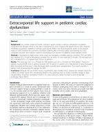
The cavo-atrial design [1, 2] (OriGen®, OriGen Biomedical) (Fig. 7.1) is inserted
via the internal jugular vein with the tip positioned in the low right atrium near the
IVC ostium. It has two drainage ports, one distal at the inferior atrium and one
proximately in the superior vena cava, with the reinfusion port in the mid right
atrium directed at the tricuspid valve. The proximity of the distal lumen to the reinfusion port allows some recirculation, but effective blood flow remains adequate.
Placement is somewhat easier than the bicaval design since the IVC does not have
to be accessed.
7
Vascular Access for ECLS
135
Fig. 7.1 A dual-lumen venous cannula, designed for drainage from the SVC and inferior right
atrium with reinfusion into the mid right atrium. (Reprinted with permission from OriGen
Biomedical)
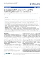
The bicaval design (Avalon Elite®, Maquet) requires insertion via the internal
jugular vein with the cannula traversing the right atrium and the tip positioned in the
IVC [3, 4] (Fig. 7.2). The drainage lumen extends the length of the cannula with
drainage ports in both the IVC and SVC. The reinfusion lumen is shorter, terminating in the right atrium with the reinfusion port directed toward the tricuspid valve.
This bicaval drainage design effectively separates the upper and lower venous systems and results in low recirculation with more effective blood flow.
The third design is similar to a hemodialysis catheter with a single proximal
drainage lumen and a distal reinfusion lumen [5]. This catheter is intended for lowflow extracorporeal circuits used for carbon dioxide removal (ECCO2R; Chap. 4). If
the cannula flow exceeds the insertion vessel flow, recirculation will limit effective
flow, but placement in the internal jugular or femoral and iliac veins usually assures
adequate blood flow.
Determinants of Cannula Blood Flow
Blood flow through vascular cannulas is driven by the difference between the
pressure at the hub of the cannula and the intravascular pressure at the tip of the cannula. Although a cannula is cylindrical in shape, in which the relationship between
flow and pressure is expected to be linear in the presence of laminar flow, the
relationship is only approximately linear over a portion of the flow range (Fig. 7.3).
136
S.A. Conrad
Fig. 7.2 A dual-lumen
venous cannula, designed
for combined drainage
from the IVC and SVC and
reinfusion of blood into the
right atrium for
venovenous extracorporeal
support
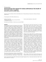
Fig. 7.3 Representative pressure-flow relationships for various size single-lumen cannulae. The
graph depicts the nonlinear relationship between flow and pressure due to a combination of laminar and disturbed/turbulent flow resulting from the complex geometry of the catheter
The Hagen–Poisseulle equation for laminar flow, although not directly applicable
to cannula flow, does illustrate the major determinants of blood flow ( Q ):
DP × r 4
Q =
m ×L
7
Vascular Access for ECLS
137
where ΔP is the pressure difference, r and L are the cannula radius and length,
respectively, and μ is blood viscosity. Maximizing blood flow involves use of the
largest diameter cannulas that can be safely inserted, and keeping the length as short
as possible. The nonlinearity of actual pressure-flow curves most likely comes from
the tip of the cannula, which includes side holes and a tapered tip, causing a departure from purely laminar flow.
Patient Preparation
Determination of Vessel Size
During surgical cannulation the vessel is exposed and cannula size selection can be
made visually at the time of cannulation. Determination of cannula diameter prior
to percutaneous cannulation, however, requires imaging. Without vessel sizing the
use of too large a cannula can result in venous obstruction, failure to cannulate, or
other complications such as vessel laceration or transection. Too small a cannula
can result in suboptimal blood flow and ineffective support.
Bedside ultrasound with a vascular transducer can provide high quality images
of the cervical and femoral vessels. Vessel size can be obtained by using the built-in
measurement tools and converting to the French gauge system described by JosephFrédéric-Benoît Charrière [6] used for sizing cannulas. In the case of vessels with a
circular shape, conversion of vessel diameter in mm to French size is accomplished
with the following simple formula:
Fr = D(mm ) ´ 3
The chosen cannula size should be slightly smaller than the measured vessel to help
assure successful placement and prevent complete obstruction of blood flow.
Infection Control
Infection is not an uncommon risk during prolonged extracorporeal support [7].
Since extracorporeal support may be required for periods of weeks, steps to prevent
infection are warranted, and strict attention to skin asepsis is mandatory during cannulation. Full surgical skin preparation can be accomplished with both aqueous and
alcohol-based chlorhexidine solutions, and should be applied according to the manufacturer’s recommendations. For example, with aqueous-based 4 % chlorhexidine,
a 2 min scrub, allowing the skin to dry, then repeating the scrub is the recommended
technique.
Peri-procedural prophylaxis with intravenous antibiotics can be considered for
patients who are not receiving antibiotics, and with choice of antibiotic and schedule
138
S.A. Conrad
provided according to the institutions guidelines. Continuation of prophylactic
antibiotics for the duration of ECLS support, other than required for treatment of
underlying infection, is not recommended [8]. Following insertion, strict aseptic
technique for prevention of cannula-associated infection is mandatory. Since
patients on ECLS may be fully dependent on support for weeks, simple redressing
and observation for development of infection should be replaced with an active
approach. Our approach is to perform a 2 min surgical scrub of the site with aqueous
4 % chlorhexidine every 24 h.
Insertion Technique
Three techniques for cannula insertion are commonplace. Historically, all cannulations were performed by surgeons using an open surgical technique. While some
vessels still require an open approach, surgical cannulation in most cases has been
replaced with percutaneous cannulation, and performed by surgeons, interventionalists, intensivists, and emergency physicians.
Percutaneous
Percutaneous cannulation has been used successfully for venovenous support [9],
and is preferred since it is associated with a lower incidence of cannulation-site
bleeding and infection. It also is non-obstructive, allowing blood flow around the
cannula. It can be used for arterial (other than carotid) as well as venous access.
The same Seldinger technique used for smaller vascular access catheters is used
for ECLS cannulae, but with multiple dilators of no more than 4 Fr difference in size
(typically 12, 16, 20, 24, 28, and 30–32 Fr) with the largest size approximately
equal to the size of the cannula to be inserted. Prior to insertion, vessel size is determined with ultrasound and an appropriate size cannula is chosen. Under adequate
sedation a neuromuscular blocker is administered to prevent respiratory effort.
Under aseptic conditions and following infiltration of a local anesthetic, the vessel
is identified with ultrasound and an approach is chosen to avoid injury to neighboring vessels, since vessels may overlie each other. The access needle is inserted using
ultrasound to guide it into the center of the vessel, and a .035″ to .038″ guidewire is
advanced. Fluoroscopy is invaluable for preventing guidewire misadventures during
advancement, and recommended for the bicaval dual-lumen cannula to assure
placement of the wire across the atrium.
Following placement of the guidewire, a skin incision is made just large enough
to admit the cannula. The tract is then dilated sequentially to the target size. The
cannula is placed over its tapered loading dilator, and advanced into position. Using
a tubing clamp to control back-bleeding, the guidewire and dilator are removed, and
7
Vascular Access for ECLS
139
the cannula flushed with heparinized saline (2 units/mL) to maintain patency until
attached to the ECLS circuit and extracorporeal circulation has begun. The cannula
is sutured to prevent decannulation, taking care to avoid crimping the cannula or
providing a pivot point for cannula kinking.
Percutaneous cannulation of the femoral artery may result in inadequate distal
perfusion and the development lower limb ischemia. This can be managed by percutaneous placement of a retrograde arterial cannula (6–8 Fr), or surgical cannulation of the posterior tibial artery to assure adequate perfusion of the limb.
Semi-open
A variation of percutaneous cannulation preferred by some surgeons is a technique
which combines percutaneous skin and vessel insertion under direct visualization
through an incision over the vessel entry point. Following sedation and neuromuscular blockade, skin preparation and anesthetic infiltration, an incision is made over
the expected vessel entry point, and dissection is carried out to visually expose the
vessel. A needle puncture is made distally to the incision, and a tract is created as
for percutaneous insertion. Access into the vessel is performed visually. The subcutaneous tissue and skin are closed. Vessel ligation and incision are avoided, and the
skin can be closed without the cannula exiting through the incision, reducing bleeding complications.
Open Surgical
The preferred technique for cervical cannulation when carotid arterial access is
required is the open surgical technique (Fig. 7.4). Following sedation, neuromuscular blockade, and skin preparation, an incision is made perpendicular to the axis
of the vessel, and carried down to expose the cervical vessels. The cannula can be
sized by visual comparison with vessel size. The vessels are freed from surrounding tissue, and ligatures are placed proximal and distal to control bleeding. An
arteriotomy (or venotomy) is made, and the cannula with its blunt-tipped loading
dilator is inserted into the vessel while loosening the proximal ligature to admit
the cannula. Following insertion to the proper depth, the ligatures are secured,
typically with pledgets to prevent vessel injury, as vessel repair may be performed
at decannulation. The subcutaneous tissue and skin are closed around the cannulae, taking care to securely close the skin around the cannulae. The above description is generic, and variations are numerous, subject to the surgeon’s preferences
and experience.
If open cannulation is performed on the femoral artery which, unlike the carotid,
has no collateral circulation, then a smaller retrograde perfusion catheter is placed
140
S.A. Conrad
Fig. 7.4 Technique of surgical cannulation of the cervical vessels for extracorporeal life support.
The technique for the femoral vessels is similar. (Used with permission from [11])
to prevent limb ischemia. An alternative approach to arterial cannulation for the
femoral or subclavian artery is to attach an end-to-side vascular graft to the artery,
and cannulate the graft. This allows use of a large cannula for optimal blood flow
and avoids obstruction and distal ischemia. The graft approach may also be more
suitable for long-term venoarterial support.
Cannulation Configurations
The foremost decision regarding vascular access is the mode of support, which dictates the cannulation configuration. Extracorporeal life support for both respiratory
and cardiac failure was historically performed using only a venoarterial (VA)
7
Vascular Access for ECLS
141
configuration. While still the preferred configuration for cardiac failure, other configurations have been developed that are more suitable for other types of support.
Venoarterial
The venoarterial configuration drains blood from the central venous circulation and
returns it to the arterial circulation. The cervical approach is used in neonates and
infants, in whom femoral vessels are small, and since they have adequate collateral
circulation of the cerebral vessels following ligation of the carotid artery. The arterial cannula is placed into the carotid artery and advanced to the proximal innominate artery. The venous cannula is placed into the internal jugular vein and advanced
into the right atrium. This configuration supplies oxygenated blood to the proximal
aorta, but coronary and right upper extremity blood may be poorly saturated if pulmonary failure is present and the left ventricle is ejecting (Chap. 6).
Venoarterial cannulation may be performed using the femoral vessels. This configuration is suitable if the native lungs can provide adequate saturation of blood,
since in the presence of cardiac ejection, the upper half of the body is supplied by
the native heart and lungs and the lower half by the extracorporeal circuit.
Venovenous
Venovenous cannulation was introduced later than venoarterial, and is suitable for
respiratory failure with adequate native cardiovascular function (Chap. 6). It provides
oxygenated blood into the venous system and uses the native heart for oxygen delivery, making oxygenated blood available to all tissues, including the myocardium.
Cannulae for venovenous support may be placed percutaneously or surgically.
The venovenous configuration was introduced to extracorporeal support using
two single-lumen cannulae, one placed into the femoral vein and advanced to the
intrahepatic inferior vena cava for drainage, and the second placed into the internal
jugular vein and advanced to the superior cavo-atrial junction. An alternative configuration to gain better flow and reduce recirculation was to introduce three cannulae, two for drainage placed at the superior cavo-atrial junction and distal IVC
respectively, and one for return placed near the inferior cavo-atrial junction.
A major advance in venovenous support was the introduction of the dual-lumen
venovenous cannula. Developed initially for neonates and infants, cannula are now
available for adult and pediatric patients. These cannulae have a single shaft, incorporating a drainage lumen with ports in the SVC and IVC (or low right atrium) and
a reinfusion lumen with a port in the mid-right atrium. Recirculation rates with
these cannulae are lower than with the single-lumen configurations, and are negligible with the bicaval design.
142
S.A. Conrad
Veno-arterio-venous
A variation of the venovenous technique is a veno-arterio-venous (VAV) hybrid
mode, which drains from the venous system and returns to both the venous and arterial systems (Chap. 6). This configuration can provide partial cardiac support as
well as oxygenation, and is suitable for patients with respiratory failure who have a
sustained reduction in cardiac function, or cardiac failure who develop respiratory
failure, such as pulmonary edema.
Low-Flow Venovenous
Venovenous support can target carbon dioxide removal (extracorporeal carbon
dioxide removal, ECCO2R) to support lung-protective ventilation in patients for
whom oxygenation can be adequately provided through mechanical ventilation
(Chaps. 4 and 6). A venovenous configuration using smaller single-lumen cannulae
or a dual-lumen cannula with low blood flow (1–1.5 L/min) can effectively provide
significant CO2 removal. Commercial systems are emerging which use an integrated
pump and oxygenator and 15–16 Fr dual-lumen catheter, similar in design to a
hemodialysis catheter, placed in the jugular or femoral vein.
Arteriovenous
Another approach to extracorporeal carbon dioxide removal is arteriovenous carbon
dioxide removal (AVCO2R), sometimes termed interventional lung assist (iLA).
This configuration involves cannulation of the femoral vessels with a small arterial
cannula (12–14 Fr), and a 16–18 Fr venous cannula, attached to an oxygenator
using short tubing. The patient’s arterial blood pressure provides the gradient for
blood flow, avoiding the need for a pump. The major disadvantage is the need for
arterial access, but with smaller cannulae the risk of arterial complications is low. It
is likely that the new generation of dedicated ECCO2R devices will replace the arteriovenous configuration, just as continuous venovenous hemofiltration (CVVH) has
largely replaced continuous arteriovenous hemofiltration (CAVH).
Transthoracic
Although much more invasive, direct cannulation of the right atrium and aortic root
through a sternotomy remains an important approach to vascular access. The most
common use is support of post-cardiotomy failure to wean from cardiopulmonary
7
Vascular Access for ECLS
143
bypass (CPB), in which the cardiopulmonary circuit is replaced with the ECLS
circuit. Typically the sternum is left open and draped. The CPB cannulae are large
and support more flow than can be achieved using peripheral access.
The transthoracic approach is associated with more bleeding and infection risk,
so is generally used for patients expected to recover quickly. If prolonged support is
required, the patient may be transitioned to peripheral cannulation, or to a ventricular assist device. This approach has also been used to provide high-flow support in
patients with severe sepsis [10].
Decannulation
When extracorporeal support is no longer required, the patient is removed from support by clamping the circuit near the cannulas and removing the circuit.
Anticoagulation is discontinued prior to surgical decannulation or arterial percutaneous decannulation, and is held shortly before percutaneous venous decannulation.
The cannulae are flushed to prevent thrombus formation.
Percutaneous venous cannulae are removed by first placing a purse string suture
in the incision, withdrawing the cannula, and securing the suture. Percutaneous arterial cannulae are removed by withdrawing the cannula and applying pressure until
hemostasis, with care not to fully compress the artery. Arterial puncture closure
devices may be used if appropriately sized. Venous cannulae placed by the semiopen technique are removed as if placed percutaneously. Short-term anticoagulation
or anti-platelet therapy is used to help prevent venous thrombus formation.
Surgically placed cannulae are removed with an open technique. The skin incision is re-opened, temporary ligatures placed, and the existing ligatures removed.
The vessel is either repaired or ligated, and the incision closed.
Complications of Cannulation
Recirculation
Recirculation occurs when reinfused blood is aspirated into the drainage cannula,
reducing the effective extracorporeal flow. It is unavoidable with the use of singlelumen cannulae. Recirculation manifests as a decrease in delivered oxygen and drop
in systemic arterial saturation. Increases in recirculation can occur with displacement of the cannula, and may require radiography to detect. It also increases with
increasing flow, such that high flows may actually reduce delivered oxygen.
Recirculation is less extensive with dual-lumen cannulae. The bicaval design is
associated with the lowest degree of recirculation, often under 3 %. The cavo-atrial
cannula has higher recirculation than the bicaval, but less than the use of two-site
single-lumen cannulation.
144
S.A. Conrad
Insertion Site Bleeding
Bleeding from cannulation sites is the most common bleeding complication. In
most instances it is minimal but can require intervention. Initial approach to management is to verify appropriate levels of anticoagulation, adequate platelet counts,
normal prothrombin time, and adequate fibrinogen levels. Reduction of anticoagulation target and the application of topical hemostatic agents may be helpful.
Bleeding can be minimized by limiting the skin incision to snugly fit the cannula
when it is inserted. In the case of surgical cannulation, failure of more conservative
measures may require re-exploration of the cannulation site.
Limb Ischemia
Ischemia of the lower limb is one of the major risks associated with cannulation of
the femoral artery. It can usually be managed by placement of a retrograde cannula
either just distal to the cannulation site or in the posterior tibial artery, to provide at
least 150–200 mL of blood flow per minute. An alternative percutaneous strategy is
to place two smaller arterial cannulae, one in each femoral, together providing the
total flow of a single larger cannula.
If limb ischemia is not detected in time, sufficient muscle necrosis can occur that
may require fasciotomy or even amputation. Careful clinical examination, Doppler
monitoring of distal pulses, and plethysmographic assessment with pulse oximetry
can help identify this condition early. Many will routinely place a retrograde cannula at the time of cannulation to minimize this risk.
Vascular Injury
Injury to the target or adjacent vessel during cannulation can result in inability to
achieve vascular access, transection of a vessel, hemorrhage into areas such as the
retroperitoneal space, exsanguination, and death. Immediate attempts at surgical
repair and completion of cannulation are required, but may not be successful. The
risk is higher with percutaneous cannulation since the vessels are not visible. The
use of ultrasound can mitigate these risks, by allowing for appropriate cannula size,
identification of adjacent vessels, selection of an approach, and guidance of the
puncture to ensure proper entry into the vessel.
Inadequate Flow
The inability to achieve the expected flow can result in the inability to achieve
adequate cardiac support (venoarterial) or persistent hypoxemia and inability to
achieve lung protective settings (venovenous), decreasing the chance of survival.
7
Vascular Access for ECLS
145
Three conditions that commonly lead to inadequate flow are placement of cannula
smaller than required, improper placement resulting in impaired venous drainage,
and hypovolemia.
Choice of cannula size should be driven by the flow needed for adequate support,
typically 50–75 mL/kg/min for an adult, and higher for pediatric patients, and can
usually be achieved with a single drainage cannula. Uncommonly, two drainage
cannulae may need to be placed. The reinfusion cannula is typically smaller than the
drainage cannula since flow is driven with a much higher pressure gradient, and is
rarely the cause of inadequate flow. Improper placement can be identified by radiography or echocardiography, and corrected.
Hypovolemia is the most common transient cause of inadequate flow. It can
result in “chattering” of the venous line, in which vascular structures cyclically collapse around the cannula resulting in intermittent flow. Volume expansion with colloid (or blood if anemia is also present) resolves the problem.
Infectious Complications
Infection of the cannulation insertion site is a challenging problem, since the patient
may be totally dependent on extracorporeal support and recannulation may be risky
or impossible. Prevention by good skin asepsis at the time of insertion and during
extracorporeal support is important to minimizing this risk. If infection does develop
and appears to be localized, then use of appropriate antibiotics may be successful.
If bacteremia develops, then consideration should be given to replacing the extracorporeal circuit after an initial treatment period with antibiotics, since seeding of
the large surface area circuit can result in persistent bacteremia. If the cannula site
infection is not responsive to antibiotic therapy alone, then recannulation may be
required.
References
1. Andrews AF, Zwischenberger JB, Cilley RE, Drake KL. Venovenous extracorporeal membrane oxygenation (ECMO) using a double-lumen cannula. Artif Organs. 1987;11(3):265–8.
2. Anderson 3rd HL, Otsu T, Chapman RA, Barlett RH. Venovenous extracorporeal life support
in neonates using a double lumen catheter. ASAIO Trans. 1989;35(3):650–3.
3. Wang D, Zhou X, Liu X, Sidor B, Lynch J, Zwischenberger JB. Wang-Zwische double lumen
cannula-toward a percutaneous and ambulatory paracorporeal artificial lung. ASAIO
J. 2008;54(6):606–11.
4. Bermudez CA, Rocha RV, Sappington PL, Toyoda Y, Murray HN, Boujoukos AJ. Initial experience with single cannulation for venovenous extracorporeal oxygenation in adults. Ann
Thorac Surg. 2010;90(3):991–5.
5. Batchinsky AI, Jordan BS, Regn D, Necsoiu C, Federspiel WJ, Morris MJ, et al. Respiratory
dialysis: reduction in dependence on mechanical ventilation by venovenous extracorporeal
CO2 removal. Crit Care Med. 2011;39(6):1382–7.
146
S.A. Conrad
6. Iserson KV. J.-F.-B. Charriere: the man behind the “French” gauge. J Emerg Med.
1987;5(6):545–8.
7. Bizzarro MJ, Conrad SA, Kaufman DA, Rycus P, Extracorporeal Life Support Organization
Task Force on Infections EMO. Infections acquired during extracorporeal membrane oxygenation in neonates, children, and adults. Pediatr Crit Care Med. 2011;12(3):277–81.
8. Extracorporeal Life Support Organization Task Force on Infections. Infection control and
extracorporeal life support 2010. />9. Pranikoff T, Hirschl RB, Remenapp R, Swaniker F, Bartlett RH. Venovenous extracorporeal
life support via percutaneous cannulation in 94 patients. Chest. 1999;115(3):818–22.
10. Maclaren G, Butt W, Best D, Donath S, Taylor A. Extracorporeal membrane oxygenation for
refractory septic shock in children: one institution’s experience. Pediatr Crit Care Med.
2007;8(5):447–51.
11. Field ML, Al-Alao B, Mediratta N, Sosnowski A. Open and closed chest extrathoracic cannulation for cardiopulmonary bypass and extracorporeal life support: methods, indications,
and outcomes. Postgrad Med J. 2006;82(967):323–31.
Chapter 8
Circuits, Membranes, and Pumps
Bradley H. Rosen
Introduction
Modern ECLS is based on highly efficient, low-resistance, gas-exchanging membranes. In order to couple the patient and artificial lung, vascular access is required
(see Chap. 7), along with tubing, a pump, and assorted means for monitoring,
safety, and infusing medications. Clinicians caring for these patients require a
working knowledge of the circuit so as to understand its clinical implications, recognize when something goes awry, and know how to intervene. This chapter
describes the components of the circuit, providing the practitioner with an understanding of how they function and interact. It is divided into two large sections: the
first describes the anatomy of the overall ECLS circuit; the second the physiology
and normal operation of each of the components.
Circuit Anatomy
Overall Circuit Considerations
Circuit designs all attempt to balance efficacy, safety, convenience, and simplicity.
There is no one-size-fits-all solution, however, since varied patients, circumstances,
and clinician preferences may necessitate that safety override simplicity or that portability trump efficacy. For example, inserting multiple stopcocks into the circuit
B.H. Rosen, DO (*)
Division of Pulmonary, Critical Care, and Occupational Medicine, Department of Internal
Medicine, Carver College of Medicine, University of Iowa Hospitals and Clinics,
200 Hawkins Drive, Iowa City, IA 52242, USA
e-mail:
© Springer Science+Business Media New York 2016
G.A. Schmidt (ed.), Extracorporeal Life Support for Adults,
Respiratory Medicine 16, DOI 10.1007/978-1-4939-3005-0_8
147
148
B.H. Rosen
Fig. 8.1 Schematic of a complex circuit design that implements all optional features, including a
compliance chamber, separate non-integrated blood analyzers, a manifold with access sites (closed
unless being accessed), and a bridge
Fig. 8.2 Similar to the previous figure, but simplified with only necessary components: pump,
oxygenator, and flow probe/bubble sensor. The blood analyzers are internalized within the pump
and oxygenator
can allow easy access for renal replacement therapy: one circuit carries out gas
exchange and dialysis. This is convenient, but each additional connector represents
an opportunity for failure (leak, thrombosis, air entrainment, rupture). In an individual circumstance, whether to conduct renal replacement using the ECLS circuit
may depend on the ease of obtaining alternate venous access, the expected duration
of renal failure, or the ECLS physician’s experience and preference with regard to
circuit complexity. Thus, circuits range from rather complex designs incorporating
many safety and monitoring functions (see Fig. 8.1) to minimalistic, simpler layouts
that lack the various bells and whistles (Fig. 8.2).
In designing a circuit, simplicity is one of the paramount concerns. While components and connectors can be cut into a circuit after purchase, each modification
produces a weak point susceptible to rupture or fibrin accumulation due to turbulence. Any such alteration should be performed while the circuit is “dry” (prior to
priming, see below), and with regard for sterility. Additionally, each Luer lock is a
site of potential air entrainment, blood leak, or microbial contamination. The majority of connections and access ports are located on the venous side of the circuit,
between the pump and the oxygenator. This is intentional: the lack of connectors on
the arterial side reduces the potential for accidental exsanguination, while the similar lack of connectors proximal to the pump inlet limits the risk of air entrainment
and gas embolism.
8
Circuits, Membranes, and Pumps
149
All circuits should involve as little tubing as possible, while allowing adequate
spacing of components and facilitating mobilization of the patient. Greater tubing
lengths incur more resistance to flow (proportional to length according to Poiseuille’s
law), necessitating higher circuit pressures and leading to more damage to blood
elements.
Circuit length and complexity also relate to the degree to which blood is exposed
to plastic surfaces and this interaction elicits an inflammatory response. It is believed
that induced inflammation may further compromise lung function, leading to further gas exchange deterioration. It has been hypothesized that heparin coating of
polymethylpentene (PMP) oxygenators serves to reduce this response [1]. An added
consequence of circuit-induced inflammation is excessive fibrinogen production
leading to increased fibrin deposition on circuit surfaces. Further, this inflammation
promotes platelet adherence, elevating the risk of thrombosis which impairs oxygenator function [2]. Cellular deposition along the membrane surface (on the blood
side) correlates with a rising resistive pressure across the device [3]. Some fibrin
deposition within the oxygenator and circuit is unavoidable (apparent first on the
venous side), but excessive deposition is deleterious to circuit function.
There are several additional implications of circuit length. The greater the surface
area, the more that medications commonly used in the care of critically ill patients
are subject to adsorption. Antibiotics (meropenem, cefazolin, and vancomycin),
sedatives (midazolam), and analgesics (morphine, fentanyl, and acetaminophen) are
all meaningfully adsorbed, to a degree related to the lipophilic nature of the drug.
Antibiotics are only moderately affected (65–85 % recovered after 180 min), but
midazolam and fentanyl are severely adsorbed with less than 1 % recovered [4].
Even if an agent is not adsorbed, the extracorporeal circuit expands the volume of
distribution of any pharmaceutical due to the volume of blood within the circuit itself
(up to 1 L). Tubing length will also contribute significantly to the volume required to
prime the circuit, producing hemodilution. Finally, tubing surface area also relates to
the degree of heat loss. This can be substantial, such that ECLS circuits must incorporate a means for temperature control (see Heat Exchanger below).
Circuit Priming
Priming refers to the process by which the gas (ambient air present at manufacture)
is replaced with a physiologically compatible fluid. For ECLS in adults, the circuit
is primed with crystalloid fluids, such as normal saline, Ringer’s lactate, or proprietary mixed electrolyte solutions (e.g., Plasma-Lyte® or Normosol®). Purchased circuits come attached to a large, empty priming bag. The bag is filled with sterile
crystalloid, clamps are opened to the venous and arterial limbs, and the priming bag
is raised to allow gravity to move the fluid into the circuit components while air
moves to the priming bag. The volume necessary to prime a given circuit depends
on the priming volume of each component (oxygenator, heat exchanger blood
phase, pump, bridge, manifold, and tubing) and directly relates to the degree of
150
B.H. Rosen
hemodilution that follows. For pediatric and neonatal ECLS, hemodilution is prevented by priming the circuit with blood, but this is not necessary for adults where
the typical priming volume averages 750–1000 mL for a complex circuit design and
for a simple one as low as 300 mL. In fully primed condition, a circuit can be stored
for a period of at least 30 days, although each institution has its own policies regarding shelf life. Priming with a colloid may shorten the shelf life of a primed circuit,
another reason many programs choose a crystalloid prime. A simplified ECLS circuit can be fully primed in less than 10 min due to the microporous nature of the
membranes in use. Once the circuit is primed, the heat exchanger can be turned on
to raise the temperature to 37 °C before connecting the patient, as long as time permits. Cardiopulmonary bypass circuits are often primed first with carbon dioxide
(to displace oxygen and nitrogen), hastening the subsequent fluid priming process,
but this is not generally done for ECLS circuits.
Orientation to the Circuit
ECLS circuits can appear intimidating; especially when one realizes that 5 L of
blood rushes through it each minute. A systematic approach to the intricacies of the
circuit and its components keeps the clinician from becoming overwhelmed, so we
begin with a brief, general tour. Figure 8.1 represents a comprehensive schematic of
a circuit, whereas Fig. 8.2 shows a greatly simplified design with few extraneous
components. In each instance, we describe the circuit beginning with the outflow
(venous) cannula, proceeding through the gas-exchanging membrane, and ending
back at the patient through the inflow cannula, which may enter an artery (venoarterial or VA ECLS) or vein (venovenous or VV ECLS). Sometimes used for venovenous ECLS, dual-lumen cannulas allow blood to exit and enter at the same site but,
for illustration purposes, we have separated these in the figures.
Starting with the outflow cannula at its exit from the patient (internal jugular or
femoral vein, or right atrium), the distal end is connected to large-diameter conducting tubing. This is an important point for inadvertent disconnection, especially
immediately following the initiation of ECLS if the tie bands were not securely
fastened. In addition, like other areas of the circuit where there is turbulence or
stasis, this is a common site for thrombus to form. Careful examination of this connection is an essential part of the regular circuit check (see Chap. 10). The conducting tubing should be kept relatively short in order to reduce resistance to blood flow,
surface area of contact with blood, and the priming volume. The conducting tubing
leads to a centrifugal pump (in some designs a compliance chamber or bladder precedes the pump as in Fig. 8.1) before entering the membrane oxygenator. As there
is considerable heat loss as the blood traverses the circuit, a heat exchanger is necessary to rewarm the blood to body temperature (this may be incorporated into the
oxygenator and hidden from direct view). If added separately, the heat exchanger is
placed proximal to the oxygenator. The oxygenator also receives the sweep gas
(usually oxygen), being joined to wall oxygen or an E-cylinder through a flow
8
Circuits, Membranes, and Pumps
151
meter. The newly arterialized blood completes its extracorporeal course through the
inflow cannula, delivering oxygenated and warmed blood to the vascular system.
Outflow and inflow cannulas may be bridged directly by a length of large-diameter
tubing (the “bridge”; see Fig. 8.1) connected through two high-flow stopcocks.
When opened, the bridge offers a shunt to keep blood flowing within the circuit
while clamps are used to isolate the patient. In so doing, the clinician can judge
whether the patient has recovered sufficiently to sustain respiration and circulation
without ECLS (see Chap. 13). This is important during VA ECLS, but a bridge is not
needed for VV support since weaning can be conducted by reducing or eliminating
gas flow to the membrane while leaving circuit flow to the patient undisturbed.
During most ECLS operation the bridge remains closed and, because any blood
within is stagnant, blood is generally displaced by saline when the bridge is closed.
In order to monitor circuit function and to prevent complications, devices to measure pressure and flow and to detect bubbles are included, and information is relayed
to a console. Typically, pressure is measured on the venous side of the pump (“P1”),
providing information about how much suction is required to draw the needed circuit
blood flow. Two additional pressure transducers (“P2” and “P3”) flank the oxygenator
so that its resistance can be estimated based on the drop in pressure across the
membrane(“delta-P”). In addition, P3 displays the pressure that drives flow back to
the patient. Circuit blood flow is monitored using an ultrasonic flow probe, since
centrifugal pumps do not guarantee a fixed relationship between revolutions per minute and volume displaced, as was true for roller pumps. The flow probe may be integrated within the pump or added as an aftermarket device. Ultrasound probes are also
used to identify bubbles, so some circuit designs utilize the same sensor for both flow
measurement and bubble detection. Bubbles distal to the oxygenator can produce
systemic embolism and are especially dangerous in VA modes.
Spectrophotometric sensors allow real-time measurement of such values as PO2,
PCO2, pH, SaO2, SvO2, and hemoglobin concentration, among others. These sensors
must be calibrated periodically by comparing the displayed value against a blood sample analyzed simultaneously using conventional laboratory methods. The console
receives data from various devices along the circuit, displaying pump speed, flow, pressures, temperature, and other physiological information. The console also may display
alarm notifications and allows the user to adjust the pump, heat exchanger, and other
functions. The console generally is integrated with the power supply and battery.
Ports are included in the circuit so that blood can be sampled and agents can be
infused. These are often collected in a manifold consisting of a series of Luer lock
connections with a three-way stopcock controlling flow to each. The manifold
derives from the region between the centrifugal pump and the oxygenator (a “safe
zone” of interruption) and re-infuses proximal to the pump, so that small amounts
of entrained air can be eliminated by the oxygenator. Various infusions of medications and anticoagulant agents may be connected to the circuit through these ports,
but more often, other vascular access is utilized (see Chaps. 7 and 10). Sufficient
flow can be drawn from the circuit so as to combine renal replacement therapy
(RRT) and gas exchange simultaneously, avoiding the need for invasive vascular
access solely for dialysis.
152
B.H. Rosen
Function of the Circuit Components
Cannulas and Tubing
Single- and double-lumen cannulas are described more fully in Chap. 7. Cannulas
tend to be wire-reinforced to limit kinking and occlusion. They are attached to the
circuit tubing by means of adaptors and these connections are secured by tie bands.
Tubing is clear, medical grade polyvinylchloride (PVC) allowing the clinician to recognize blood color (as a clue to circuit function and recirculation) and to identify
fibrin, clots, and gas bubbles. Tubing can be clamped and, when changing out a circuit
due to oxygenator failure for instance, cut and reconnected to reinstitute circuit flow.
Compliance Chamber
This device was previously employed when roller head pumps were more common,
as a safety device to dampen any excessive negative pressure generated by the
pump, rather than causing cavitation or hemolysis in the patient. Essentially an
external venous reservoir, this device may also provide information regarding relative hypovolemia. Collapsing of the compliance chamber would suggest to the clinician that flow through the circuit be slowed or additional fluid volume be
administered. With broad use of centrifugal pumps, compliance chambers are generally felt to be an unnecessary complexity.
The simplest design is a silicone bladder with inlet and outlet ports, placed
between the outflow cannula and the pump (Fig. 8.1). A pressure transducer can be
used to signal an alarm or to slow or shut off the pump if negative pressure reaches
a degree that could result in cavitation within the venous system. Various designs
have different port sizes, priming volumes, and orientations. One device is a vertically oriented inline reservoir consisting of a compliance balloon housed within a
PVC chamber. This obviates placing the device on the ground and the lengths of
tubing to the bladder and from it. The vertical orientation may also allow for a more
constant flow assisted by gravity, reducing likelihood of settling blood and thrombosis, as well as entrainment of gaseous bubbles at the top of the chamber.
Additionally, this device can be heparin-coated and is FDA-approved for use in
ECLS. It is offered in a standard size with 20 mL priming volume and ¼-in. ports,
as well as a larger version with 115 mL priming volume and 3/8-in. ports [5].
Pumps
There are two types of pumps employed in ECLS circuits: roller/occlusive and centrifugal pumps. Practitioners of modern ECLS have settled on the centrifugal pump
design as the safer of the two.
8
Circuits, Membranes, and Pumps
153
Roller Head (Occlusive) Pumps: The pump itself has two roller heads within an
enclosure and one head contacts (and variably occludes) the tubing at all times.
These roller heads must be properly adjusted to accurately account for blood flow
[6]. They are placed 180° to each other, to pull blood from the venous limb and
simultaneously push it forward along the circuit path. The length of tubing within
the enclosure is termed the “raceway,” and that section is advanced or withdrawn
periodically to avoid foci of excessive wear on the tubing. This necessitates a significantly longer circuit when a roller pump is employed, and accordingly a larger priming volume. Another limitation that roller pumps impose on circuit design is that
they must form the base of the circuit, requiring more extensive lengths of tubing.
Outside of restricting circuit design, roller head pumps have intrinsic limitations
arising from the fact that the device operates on the principle of positive fluid displacement. This allows it to generate excessive positive pressures if, for example,
there is a kink in the outflow tubing, or very negative suction (due to intravascular
hypovolemia). It was this attribute that mandated compliance chambers when roller
head pumps were more commonly used. A high positive pressure was required to
drive blood through older silicone rubber membrane lungs, but newer, low-resistance
membranes make this unnecessary.
Flow is calculated based upon the length and diameter of the tubing within the
raceway, combined with the number of pump revolutions. Higher flow (more revolutions) leads to increased wear on tubing and can cause the liberation of microscopic particles of tubing due to material fatigue, termed spallation, and resulting
microembolism to the patient [7]. Specific types of tubing are recommended for use
within the raceway due to their resistance to wear compared with other tubing [8].
In case of emergency events, the pump may be operated manually by a handcrank and newer models are equipped with an internal battery backup of limited
duration. Advantages of roller pumps include lower cost; lower direct pump prime
volume (although more tubing is necessary); and afterload-independent flow.
Disadvantages include the need for longer tubing; location at the base of the circuit
(in current designs manufactured); spallation and microembolism; and challenges
in properly setting the occlusion.
Centrifugal pumps: These devices increasingly employ a magnetically driven
impeller within a spiral housing. The impeller imparts mechanical energy to the
blood, raising velocity and pressure as it moves from the center of the vortex to the
periphery. The housing constrains and directs the blood flow toward the circumference where it exits the pump. This principle differs entirely from that employed in
roller head pumps, producing several advantages and compromises. Where roller
head pump flow is independent of afterload (to the point of causing tubing rupture!),
a centrifugal pump is unable to overcome excessive afterload. Instead, flow will
drop as afterload increases, despite an unchanged pump rotation speed. In a similar
vein, a centrifugal device is unlikely to cause cavitation at the outflow cannula, as it
is unable to generate sufficiently negative pressure. Of course, this means that hypovolemia tends to threaten the adequacy of circuit flow when a centrifugal pump is
used. This lack of absolute relationship between pump revolutions and blood flow
necessitates a flow meter. An increasing discrepancy between pump speed and measured flow is a strong signal of trouble with regard to function of the circuit.
154
B.H. Rosen
Should there be a complete loss of power, these pumps can also be hand-cranked.
Internal batteries provide up to 90 min of support without an external power source.
Advantages of centrifugal pumps include reduced tubing length; safety benefits
due to absent issues of spallation, microemboli, and raceway rupture; and greater flexibility in circuit design because the pump does not need to be at the base of the unit.
Disadvantages include direct priming volume required for the pump (although
tubing length is reduced) and blood flow that depends on preload and afterload
(requiring a blood flow probe). Centrifugal pumps were initially reported to produce
unacceptable rates of hemolysis due to heat generation, but engineering improvements have solved this problem [9]. Designs have evolved to reduce hemolysis and
the risk of gaseous microembolism [10, 11], changing the landscape of ECLS circuits and leading to worldwide adoption of the technology [12, 13].
Membrane Oxygenators
The ideal membrane lung would be highly permeable to relevant gases (O2 and
CO2) while resisting fluid transudation from the blood to the gas phase (termed
“plasma leak”). Blood should flow through the device with minimal resistance,
allowing high flows with little pressure and without trauma to blood elements.
Surfaces exposed to blood would only minimally activate the host coagulation and
immune systems. These properties would be complemented by reliability, durability, and a small priming volume. The human lung juxtaposes blood and gas over a
tremendous surface area, with incredibly thin diffusion distances, yet maintains a
clear separation between blood and gas phases. Scientists and engineers have struggled to mimic these attributes: the history of ECLS is a remarkable story of inspiration, invention, and persistence (see Chap. 14).
Both PMP and polypropylene hollow-fiber membranes employ large numbers of
fine capillary tubes to carry the sweep gas while being bathed by flowing blood.
This extra-capillary blood flows countercurrent to the direction of gas movement,
increasing the efficiency of gas exchange. It is important to realize the stark contrast
in surface area when comparing an oxygenator with the human lung it attempts to
replace: most PMP devices provide at most 2 m2 of gas exchange surface while the
lung exposes upwards of 70 m2 to blood flow. Additionally, in the best membrane
lungs, oxygen must diffuse 150 μm from sweep gas to blood, whereas the comparable distance within the lung is a mere 0.5 μm. These disadvantages are offset by
increasing the effective dwell time of the blood within the artificial lung. In addition, so called “secondary flows,” which describe the mixing of blood around the
gas–fluid interface due to purposefully created turbulence, further enhances gas
transfer. Blood cells are regularly being brought into close approximation with the
gas-filled capillaries, effectively reducing diffusing distance [14, 15]. This layout
allows for up to a two and a half-fold reduction in surface area necessary for gas
exchange [16]. Typical gas-exchanging capacities for membrane lungs are shown in
Figs. 8.3 (oxygen) and 8.4 (carbon dioxide). Providing sufficient oxygen transfer to
8
Circuits, Membranes, and Pumps
155
Fig. 8.3 Oxygen transfer
in mL/min as a function of
blood flow in L/min
Fig. 8.4 Carbon dioxide transfer in mL/min as functions of both blood flow in L/min and sweep
gas flow
meet the entire metabolic demand (roughly 250 mL O2/min) requires blood flow of
roughly 4 L/min. In contrast, carbon dioxide transfer is relatively advantaged; so
that much less blood flow is required, especially at very high sweep gas flow rates.
For example, nearly all of the metabolically produced carbon dioxide can be eliminated with only 1 L/min of blood flow, especially at high gas flows [17].
The most common external appearance of PMP oxygenators is an extruded
square evenly balanced on one corner (see Fig. 8.5). At the lower corner, blood
enters the device from the pump under pressure denoted as “pre-membrane” or
“inlet pressure” (typical pressures are in the range of 225–275 mmHg, certainly less
than 400 mmHg; see Table 8.1). The blood ascends to the opposite corner at the
highest elevation of the device and then flows down to the exit connector directly
opposite the inlet, by which point it is oxygenated and carbon dioxide has been
removed. At that point, the pressure (“post-membrane” or “outlet pressure”) will be
B.H. Rosen
156
Fig. 8.5 Photograph of a
membrane oxygenator
(small adult model).
Identified on this model are
the inlet and outlet for both
blood and sweep gas, as
well as the two connections
for the water heater
Table 8.1 Circuit pressures
Location in the circuit
Proximal to the pump: P1
Oxygenator inlet: P2
Oxygenator outlet: P3
Delta-P: (P2 minusP3)
Normal operating pressure
−100 to −200 mmHg
225–275 mmHg
190–260 mmHg
10–35 mmHg
less than the inlet pressure. The difference between these is called the “delta pressure” (or “delta-P”), representing the resistive pressure drop across the membrane at
the current flow. With the current generation of PMP devices, delta-P should range
from the teens to low 30s at typical circuit blood flow rates.
With regard to the pressures and the information that may be gleaned from their
trends, an elevated oxygenator inlet pressure (P2) has variable implications depending on whether the outlet pressure (P3) is also elevated. In the case where both are
elevated (delta-P is preserved), the circuit should be examined, not the oxygenator:
the distal tubing and circuit may be obstructed by kinks or thrombosis. Similar findings are seen transiently when patients cough, Valsalva, or are suctioned. When
inlet pressure rises along with an increase in delta-P, resistance within the membrane is excessive, raising concerns for thrombosis, heparin-induced thrombocytopenia, or accumulation of fibrin or cellular elements on the membrane. Ultimately,
this portends failure of the membrane.
Another major advance in modern PMP oxygenators is their low resistance to
blood flow, producing several important advantages. First, this property ushered in
the era of lower pressure, afterload-sensitive centrifugal pumps, affording the safety
8
Circuits, Membranes, and Pumps
157
features discussed above. Secondly, lower pressures translate to safer, longer-lived
circuits, conferring additional safeguards against catastrophic rupture or circuit
failure. Additionally, such low resistance to blood flow permits novel applications
of ECLS such as pumpless arteriovenous extracorporeal CO2 removal (ECCO2R)
that rely solely on the difference between arterial and venous blood pressures to
drive flow [18] (see Chap. 4).
In the modern era of ECLS, the centerpiece of the circuit is a PMP oxygenator
and these devices have eclipsed prior generations of artificial lung. Nevertheless,
other oxygenator designs are seen occasionally and include both silicone membranes first developed by Kolobow [19] (most recently marketed as the Medtronic
1-4500-A2) as well as the polypropylene microporous hollow-fiber membrane.
Silicone membrane oxygenators employed sheets enclosing a plastic polymer
screen and wrapped around a polycarbonate core. They remain the only gas
exchange device that is FDA-approved for long-term use (defined as use for more
than 6 h). However, they require priming with considerable volume (665 mL each
[20]), exhibit a large pressure drop across the membrane that limits the use of
centrifugal pumps, and are relatively inefficient in gas exchange so that at least two
large surface area units are needed per patient. Polypropylene hollow-fiber membranes are highly efficient with respect to gas exchange, but tend to develop plasma
leak (described further below). They also present a low resistance to blood flow and
need only a small priming volume, and remain in use for cardiopulmonary bypass
where they provide excellent short-term support.
Additional Limitations of Membrane Oxygenators
Rated Flow: Blood exiting the membrane is normally fully oxygenated, typically
with a PO2 in excess of 300 mmHg. As blood flow is increased, greater demands are
placed on the capacity for gas diffusion across the hollow fiber barrier. In part, this
relates to the simple volume of oxygen that must diffuse as more deoxygenated
blood is pushed through the membrane, but also to the increasing blood velocity
(thus reduced dwell time) produced at higher flows. At sufficiently high flows, the
membrane fails to fully saturate the blood. The flow threshold for full oxygenation
is termed the “rated flow.”
Plasma Leak: Hollow fiber membranes should be sufficiently permeable to allow
rapid gas diffusion, while remaining impermeable to fluid movement. Plasma leak
is the phenomenon whereby plasma phospholipids leak from the circulating whole
blood to the gas compartment of the oxygenator, then serve to propagate further
plasma leakage in a positive feedback cycle [21]. Small amounts of fluid will normally traverse the membrane and a drainage port is provided for egress. Greater
volumes signal a failing membrane, severely impairing the efficiency of gas
exchange, accompanied by a rise in delta-P, and eventually requiring exchange of
the device. Important plasma leak can be confirmed by analysis of liquid from the
gas outlet for proteins [22]. Additional implications are a significant loss of proteins