Ebook Radiography in the digital age (3/E): Part 2
Bạn đang xem bản rút gọn của tài liệu. Xem và tải ngay bản đầy đủ của tài liệu tại đây (32.7 MB, 443 trang )
Part III
DIGITAL RADIOGRAPHY
Conventional radiographs of autopsied coronal slices
through the chest and head of a human corpse, appearing somewhat like MRI images.
Chapter
28
COMPUTER BASICS
Objectives:
Upon completion of this chapter, you should be able to:
1. Overview how computer hardware and software interact to perform tasks
at high speed.
2. List the types of computers and terminals, and how they relate to radiography.
3. Overview the history and development of computers and micro-circuitry.
4. Describe how peripherals integrate with the central processing unit.
5. Describe the types of storage and main components in the CPU.
6. Describe the types of storage and major components of a typical PC.
7. Distinguish between the various characteristics of modern digital memory.
8. Analyze the differences between analog and digital data and how they relate
to radiographic images.
9. Understand the basic aspects of binary code and ASCII code.
10. Overview the general types of software and levels of machine language.
11. Define the four levels of data processing.
12. Overview the hardware components and compatibility of digital communications systems.
A computer is any machine that can perform mathematical computations, manipulate information,
make decisions and interact accurately and quickly.
All of these functions are based upon the fundamental ability of the machine to follow preprogrammed
instructions known as algorithms. Each algorithm is
a concise set of instructions for a single, specific task,
such as how to subtract two numbers that are inputted into the computer by the user. A computer
program is a collection of many hundreds or even
thousands of interrelated algorithms which allow
the user to perform a general application such as
calculating taxes, word processing, or organizing a
data base.
To avoid repetitious programming and wasteful
duplication, algorithms that will be used repeatedly
within a program, called subroutines, are written only
once and stored apart from the overall instructions,
where they can be accessed as often as needed by a
“go to” command.
Artifical intelligence (AI) describes the ability of a
machine to make decisions based on logic functions
such as “do,” “if then,” and “if else.” An example of
an algorithm for an “if else” statement might be as
follows:
429
1. Store number A inputted from keyboard at
memory address
2. Retrieve permanently saved number B from
memory to calculator
3. Retrieve inputted number A from memory to
calculator
4. Subtract B minus A
5. IF the result of step 4 is positive, (if B is
greater than A), go to line 7
6. ELSE, (if B is NOT greater than A), go to subroutine starting at line 11
7. C = [A × 0.5]
8. Print out at monitor screen: C “will be deducted from your tax”
9. Count for 5 seconds
10. Go to (next section of tax instructions)
11. Print out at monitor screen: “You cannot
deduct this from your taxes”
430
Radiography in the Digital Age
Figure 28-1
A typical microprocessor for a personal computer
(PC). This is the CPU.
12. Wait for “ENTER” command
13. Go to (next section of tax instructions)
The part of a computer that interprets and executes
instructions is called the central processing unit, or
CPU. A CPU that is contained on a single integrated
circuit chip is called a microprocessor (Fig. 28-1). The
microprocessor is the heart of the computer. We
think of the power of a computer in terms of how
much data it can input, process and output in a given
amount of time. The unit for this is millions of instructions per second, or MIPS. Actual processing speeds
range from hundreds of MIPS for microcomputers
to thousands of MIPS for mainframe computers.
This overall power is determined primarily by the
speed of the microprocessor. This speed is determined, in turn, by an internal clock. The faster the
clock, the faster the processing. Recall from Chapters
5 and 7 that the unit for frequency is the hertz, defined
as one cycle per second. For an analog clock, one cycle
represents the completion of one circle around its face
by the clock’s hand. The speed of a microprocessor
is expressed as the rate of cycles the clock can complete or count each second. As with all other aspects
of computers, we have seen this rate increase exponentially over time: Once measured in kilohertz and
then megahertz, we now talk of the speed of microprocessors in common PC’s in units of gigahertz
(billions of cycles per second) and terahertz (trillions of
cycles per second).
Perhaps the most common way to classify computers is by their size. We generally think of a computer as the “PC” (personal computer) that fits on
our desk at home. Several decades ago, the computing
power of a modern PC required a computer as large
as an entire room. All of the computing power of the
lunar module which landed on the moon is now
contained within a small hand-held calculator. As
miniaturization in electronics continues to progress,
it becomes more difficult to make clear distinctions
between sizes of computers, and the “size” of the computational power is more pertinent than the physical
size in application. With the understanding that some
overlapping of terms is unavoidable, we can broadly
categorize the sizes of computers as follows:
1. Microcomputers usually have one single microprocessor, and generally fit on a desktop such
as a PC (personal computer) or “notebook”
computer.
2. Minicomputers contain many microprocessors
that work in tandem, and are too large and
heavy to be placed on a desktop. The smallest
minicomputers occupy a single cabinet ranging
in sizes comparable to various refrigerators,
placed on the floor. Larger minicomputers can
occupy three or four large cabinets taking up a
portion of a room. CT and MRI computers are
examples of minicomputers.
3. Mainframe computers and supercomputers consist of microprocessors numbering in the hundreds or even thousands, and can support
thousands of users. They require the space of
an entire room or even a whole floor of a
building. They are used in telecommunications companies, military and government organizations, airlines, and weather forecasting
applications, to name a few.
The operating console of a standard diagnostic xray machine is essentially a microcomputer, with
about the same overall processing power as a PC, but
with all that power dedicated to the selection of
proper radiographic technique while compensating
for electronic and other variables.
THE DEVELOPMENT OF COMPUTERS
Tools for performing mathematical calculations date
back thousands of years to the abacus, invented in
Computer Basics
431
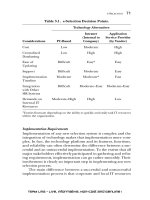
Figure 28-2
An abacus, the earliest known computing
device, used in Asia for thousands of years.
China. The abacus consisted of a frame containing
columns of beads separated by a crossbar (Fig. 28-2).
Each column held five beads below the crossbar, representing ones, and two above the crossbar representing fives. Each whole column represented a power of
10 above the column to its right, such that 13 columns
could represent numbers reaching into the trillions.
Equally impressive, the abacus could be used not only
for all four standard mathematical operations, but also
to calculate square roots and cube roots.
The first major step in the evolution of a completely automatic, general purpose, digital computer
was taken by an English mathematician, Charles
Babbage, in 1830 when he began to build his analytical engine. One hundred years ahead of his time, the
limitations of technology prevented Babbage from
completing the machine in his lifetime. Meanwhile,
another English mathematician, George Boole, devised a system of formulating logical statements
symbolically which led to the design of switching circuits in the arithmetic/logic units of electronic computers. After Babbage’s death in 1871, no significant
progress was made in automatic computation until
1937 when American professor Howard Aiken began
building his Mark I digital computer. Completed in
1944, it was the realization of Babbage’s dream, but
the Mark I still contained some components that
were mechanical rather than electronic. It could perform up to five arithmetic operations per second.
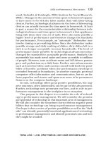
The first fully electronic digital computer was completed at the University of Pennsylvania in 1946 by J.
Presper Eckert and John Mauchly. Called the Electronic Numerical Integrator and Calculator (ENIAC),
it consisted of 18,000 vacuum tubes (Figs. 28-4 &
28-6), weighed 30 tons, and took up 1500 square feet
of floor space (Fig. 28-3). It could perform 5000
arithmetic operations per second. This same year,
John Von Neumann, a Hungarian-born American
mathematician, published an article proposing that
entire programs could be coded as numbers and
stored with the data in a computer’s memory.
Almost everything he suggested was incorporated
into the EDVAC (Electronic Discrete Variable Automatic Computer) designed by Eckert and Mauchly’s
new company. This was the first stored-program digital computer, completed in 1949.
In the meantime, a breakthrough in computer
hardware took place in 1948 with the development
Figure 28-3
The first electronic digital computer, the ENIAC, took
1500 square feet of floor space and weighed 30 tons.
(U.S. Army photo.)
432
Radiography in the Digital Age
of the first transistor at Bell Telephone Laboratories.
The transistor (Fig. 28-7), is a very small electronic
(rather than mechanical) switch, which alternately
allows or does not allow electrical current to pass
through it. Eckert and Mauchly quickly integrated the
transistor with their basic EDVAC design to produce
the much more advanced UNIVAC I (Universal Automatic Computer), completed in 1951. The UNIVAC
was mass-produced within a few years and became the
first commercially available computer. Unlike earlier
computers, it handled numbers and alphabetical
characters equally well, and was the first computer
to separate input and output operations from the
central computing unit (Fig. 28-5).
The UNIVAC I used both vacuum tubes (Fig.
28-6), and transistors (Fig. 28-7). Both the vacuum
tube and the transistor are able to represent binary
digits, or bits of computer language, by simply allowing the two states of being switched on or off. (The
“on” condition indicates a “yes” or the number 1, and
the “off ” state indicates a “no” or the number 0.)
But, vacuum tubes were bulky, and the heated filaments would often burn out just as light bulb filaments do, making them very unreliable indeed.
The transistor allowed two critical developments
to evolve: First, by the miniaturization of memory
components, the size and weight of computers
dropped dramatically, facilitating their mass production, their portability, and their use. More importantly, memory components were now solid state,
based on small crystals rather than on heated wire
filaments—this lengthened their life span as much as
100 times, and also dramatically reduced the electrical
power needed to run the computer. The economy
and efficiency of computing skyrocketed. Therefore,
the solid state transistor is perhaps the single most
important invention in history for the development of
computer hardware.
Since 1951, computers are considered to have
evolved through at least four generations based on
continued radical improvements in technology. These
Figure 28-5
Figure 28-6
The UNIVAC was the first mass-marketed computer,
and the first to separate input/output modules from
the main computer. (U.S. Navy photo.)
Vacuum tubes, with cathode pins and anode plates
(arrows). Tubes like these were the earliest switching
elements in computers.
Figure 28-4
A technician replacing a burned-out vacuum tube, one
of 18,000 such tubes in the ENIAC. (U.S. Army photo.)
Computer Basics
433
Figure 28-7
Various sizes of solid-state transistors. The
transistor, used as a switching element,
was perhaps the single most important development in the evolution of computers.
(Courtesy, Tom O’Hara, PhD.)
generations are briefly defined in Table 28-1. Since
the invention of the transistor, most advancements
have been made in the area of miniaturization. In
the mid-1960s a method was developed in which
hundreds of miniaturized components could be
chemically fused onto a small silicon chip, typically
about 1 cm in size, to form microscopic circuits.
These came to be known as integrated circuits.
Silicon is a semiconductor—it can be doped by
other chemicals to make it conduct, resist, or block
the flow of electricity. By introducing chemical impurities such as aluminum or boron in specific
arrangements, microscopic capacitors, diodes, resistors, and transistors can be created. Specific areas of
the chip are treated with various chemicals to serve
these functions. With these areas in mind, the particular circuit is first mapped out on a large board.
Special photography is used to reduced the pattern to
microscopic size, form a photographic negative and
project the pattern onto the silicon chip. More
chemical impurities are baked into specified portions of the wafer to complete the circuit.
Further advancements in this miniaturization
process have led to microprocessors which now contain millions of circuit elements within a square centimeter of silicon.
COMPUTER HARDWARE
COMPONENTS
The hardware of the computer consists of all the
physical components, including input devices, the
Table 28-1
Generations of Computers
Generation
Logic and Memory Circuit Components
Generally
Available
1st:
Vacuum Tubes for both: Conducting = filament heated = “on”
1951
2nd:
Transistors for logic: Conduction = silicon charged = “on”
Magnetic cores for memory
1958
3rd:
Integrated Circuits: Miniaturized components chemically fused onto
a small silicon chip in microscopic circuits
1965
4th:
Microchips: Enhanced miniaturization of integrated circuits
Large-Scale Integration (LSI) = thousands of elements
Very Large Scale Integration (VLSI) = millions of circuit elements
onto a 1 cm chip
1970s
1990s
434
Radiography in the Digital Age
processing system, memory and storage devices,
output devices and systems for communication.
These physical components are connected as shown
in Figure 28-8. From this diagram, it is clear that
there is a flow of information from input, output,
and memory storage devices to the central processing
unit or CPU. This flow of data is carried by a multiwire line called a bus. The connections of bus lines
to each of the devices are called ports. Serial ports
transmit data sequentially one bit at a time. The
common USB (Universal Serial Bus) has several
transmission wires and prongs so that it can transmit several data streams simultaneously, however,
each of these channels still uses a serial protocol,
hence its name.
Input/output or I/O devices, also called peripherals, transmit data to and from the computer.
Input devices include the keyboard, the mouse, the
trackball, the joystick, the touchpad, and the light
pen. Most of these are pointing devices which con-
trol the location of the cursor (usually an arrow),
which indicates the insertion point on the screen
where data may be entered. These devices all require
the user to enter information one character or
menu selection at a time, and are somewhat slow.
In order to more quickly copy information directly
from a document, or from an audio or visual scene,
source-data entry devices were developed. These include bar code readers, scanners and fax machines,
sensors, microphones, and digital cameras and
camcorders.
Output devices include printers, display screens
and speaker systems. The display screen or monitor
is typically a liquid crystal display (LCD)—two plates
of glass with a substance between them that can be
activated in different ways to make the crystals
appear lighter or darker. To create smooth-looking
letters and numbers on a monitor screen, a character
generator is used to illuminate selected dots in a 7 ×
9 matrix for each character.
Figure 28-8
Workstation
Computer
CPU
OUTPUT
INPUT
Additional
primary
memory
Laser
camera
Optical
jukebox
External
storage
The central processing unit directs data flow from input devices, between primary and secondary memory and
the arithmetic/ logic unit, and to output devices.
Computer Basics
A video display terminal (VDT) uses a keyboard
and mouse or trackball for input, and a display screen
for output. A dumb terminal cannot do any processing on its own, but is used only to input or receive
data from a host computer, such as is done at airport
check-in counters. An intelligent terminal has builtin processing capability and memory, but does not
have its own substantial storage capacity. Most x-ray
machine consoles would be categorized as intelligent
terminals.
Most modern printers are either ink-jet printers
or laser printers. Ink-jet printers place an electric
charge onto small drops of ink that are then sprayed
onto the page. Laser printers form an image on a
drum which is then treated with a magnetically
charged ink-like substance called toner, and then
transferred from the drum to paper. While ink-jet
printers are quieter and less expensive, they can
print only 10 to 20 pages per minute.
Laser printers have their own memory to store
such information as fonts separate from the computer, and their own limited data processor. They
provide sharper resolution in the image (up to 475
dots per cm), and can print from 32 to 120 pages per
minute depending on the power of the computer
they are connected to.
Most radiographic images are viewed as soft copies
on the LCD monitor screen. Sometimes it is desirable
to print them out on transparent plastic film which
can be hung on an illuminator or viewbox for examination, or physically carried from place to place.
Images or text that have been printed onto paper or
plastic film are referred to as hard copies.
The Central Processing Unit
The central processing unit (CPU) performs data manipulation in the computer. It tells the computer
how to carry out software instructions. The CPU for
a mainframe computer may be large enough to
occupy its own separate cabinet, while the CPU for
a typical PC is usually a single microprocessor. All
CPU’s may be divided into two basic components:
The control unit, and the arithmetic/logic unit. These
two operate on information and data retrieved from
a primary memory storage system.
The control unit directs the flow of data between
the primary memory and the arithmetic/logic unit,
435
as well as between input devices, the CPU, and
output devices. The control unit is analogous to a
traffic cop directing the flow of traffic through an
intersection. It tells input devices when to start and
stop transferring data to the primary memory. It
also tells the primary memory unit when to start
and stop transferring data to output devices.
The control unit coordinates the operations of
the entire computer according to instructions in the
primary memory. It is programmed to select these
instructions in proper order, interpret them, and
relay commands between the primary memory and
the arithmetic/logic unit. Each set of instructions is
expressed through an operation code that specifies
exactly what must be done to complete each task.
The operation code also provides addresses that tell
where the data for each processing operation are
stored in the memory.
Somewhat like a very sophisticated hand-held
calculator, the arithmetic/logic unit (ALU) performs
all the arithmetic calculations and logic functions
required to solve a problem. Data to be operated
upon must be retrieved from addresses in memory,
and are temporarily held in the ALU’s own storage
devices called registers. These registers are connected
to circuits containing transistors and other switching devices.
To perform arithmetic and logic operations, electrical signals must pass through three basic circuits
called the AND-gate, the OR-gate, and the NOT-gate,
used in different combinations. One combination of
these gates results in subtraction, another selects the
larger of two numbers, and so on. The result of a calculation is first stored in the ALU’s main register
called the accumulator. Results may then be exported
from the accumulator to internal or external memory,
or directly to an output device such as a display
screen.
Primary memory is also referred to as main
memory or internal memory, mostly stored on chips.
Four sectors of primary memory space are reserved
for distinct functions as follows:
1. The program storage area retains program
statements for a specific application, transferred from an input device or secondary storage. Upon the request of the control unit, these
instructions are “read” and executed one at a
436
Radiography in the Digital Age
time to perform the operations of a saved program.
2. The working storage or scratch-pad storage area
temporarily holds data that is being processed
by the arithmetic/logic unit, and intermediate
results.
3. There is a designated temporary storage area
for data received from input devices which is
waiting to be processed.
4. There is a designated temporary storage area
for processed data waiting to be sent to output
devices.
The unit for measuring storage capacity is one
byte, consisting of eight bits (binary digits) of information. The significance of this number is that eight
bits are sufficient to create a single character which
can represent almost any alphabetical letter, number,
other value or symbol needed to communicate. The
bit, an acronym for binary digit, is the smallest unit
of storage, consisting of a 0 or 1.
An address is assigned to each permanent character
stored within the memory. Therefore, each address
consists of eight storage units, whether all of them
are needed or not to contain a particular character.
Just as the number of a particular mail box at the
post office has nothing to do with what is contained
therein, the addresses within computer memory are
only designated locations where bytes are stored, and
have nothing to do with the particular character
stored there. They are necessary for the control unit
to locate each character when it is needed.
Physically, most primary memory is contained in
RAM (random access memory) and ROM (readonly memory) chips mounted on boards and connected directly to the CPU. Most computers have
slots for additional boards of RAM chips to be inserted (Fig. 28-9) which generally speeds up the
computer’s response time.
The motherboard or system board is the main circuit board for a computer, usually the largest board
within the casing (Fig. 28-10). It anchors the microprocessor (CPU), RAM and ROM chips and other
types of memory, and expansion slots for additional
circuit boards such as video and audio cards that enhance specific capabilities of the computer.
The power supply for a computer must be carefully controlled. Most computer circuits are designed to operate at 5 volts or 12 volts. A power
supply box (Fig. 28-11), includes a step-down transformer (Chapter 7) and resistors used to reduce the
voltage of incoming electricity to levels that will not
burn out delicate computer components. Additional
resistors leading into specific devices may be found
on the motherboard.
Computer components also require a steady, reliable supply of power that will not be immediately
affected by split-second interruptions, reductions or
surges in the incoming electricity supply. For this
purpose, numerous capacitors may be found on the
motherboard, which store up incoming electrical
charge and then release it in a controlled, constant
stream.
Figure 28-11 gives a broad overview of the major
components one will see upon opening the processor
casing for a typical PC. These include the power
supply, optical disc drives (CD and DVD) and flash
memory drive, and the motherboard with the CPU
(microprocessor), banks of RAM chips and slots for
additional memory, banks of ROM chips, and various
attached cards containing audio, video, and modem
circuits.
Figure 28-9
RAM chips mounted on a removable
board.
Computer Basics
437
Figure 28-10
The motherboard from a PC, showing A, the
microprocessor (CPU) with a cooling fan over
it, B, banks of RAM, and C, slots for additional circuit cards.
Secondary Storage Devices
Several physical formats are available for the storage
of secondary memory. Hard disc drives (Fig. 28-12),
include one or more thin, rigid discs of glass or metal.
Both sides of each platter are coated with a very thin
layer of ferromagnetic material, (see Chapter 6). A
small, button-like read/write head is suspended by an
arm just over each surface of each platter (Fig. 28-12).
With the disc spinning, when electrical current is
passed through this head, magnetic fields are generated around it which magnetize the microscopic
fibers on the surface of the disc. As the electrical current varies, the magnetic field around the read/write
head changes shape and orientation. This results in
the north and south poles of the magnetic elements
or fibers on the disc being “pointed” in different
fixed directions, such that they are arranged in distinct patterns representing the data.
For a disc to be read back, electrical current being
fed to the read/write head is shut off so that it is in a
passive “listening” mode. As the disc spins past it, by
electromagnetic induction (Chapter 7), the magnetized
elements passing by the read/write head induce a
small electrical current flowing back into the system,
whose patterns precisely mirror those of the original
recorded data.
Data is recorded onto discs in individual circular
tracks (rather than a spiral track), forming a series
of closed, concentric rings. When the read/write
head completes reading one track, it must “jump” to
the next one. As with a CD music player, a slight
microsecond delay in outputting data allows these
jumps to be made while the output flows continuously and seamlessly. Hard discs can squeeze thousands of tracks per centimeter within their radius.
The tracks are organized in up to 64 invisible sections called sectors for storage reference. Figure 2813 shows how sectors of data and their addresses are
arranged in a circular track.
Figure 28-11
Inside of a typical PC, showing A the power supply, and
B, brackets to hold disc drives. The motherboard can
be seen at the lower right.
438
Radiography in the Digital Age
Figure 28-12
Inside of a hard drive unit, showing one of three magnetic read-write heads (horizontal arrow), and a
double-disc (vertical arrow).
As shown in Figure 28-14, multiple hard discs can
be stacked within a disc drive, with several read/write
heads suspended between them on different arms.
When they are stacked this way, the reading speed
can be enhanced by using the cylinder method to
locate data; this involves reading one circular track,
then electronically switching to the same track on the
next disc below, where the read/write head is already
in position, rather than waiting for the read/write
arm to mechanically move to the next outer track on
the same disc. When information is recorded, it is
placed vertically on all of the corresponding tracks
throughout the stack of discs before moving the
read/write heads to the next outer track. One can
visualize the data stored on virtual cylinders that are
arranged concentrically (Fig. 28-14).
Hard disc drives for a typical PC can hold 4 to 6
terabytes (TB) of memory per disc, and spin at
high speeds, making them suitable for recording radiographic images. Larger computers use removable
fixed disc drives with stacks of up to 20 hard discs,
reaching memory capacities that are measured in
terabytes (trillions of bytes). A mainframe computer
may have as many as 100 stacked disc drives, each
sealed within its own cabinet, attached to it.
A Redundant Array of Independent Discs (RAID)
is a storage system with two or more hard drives that
duplicate storage of the same information. In this
way, if one disc drive fails or is damaged, other drives
which may have their own independent power supplies and connections to input and output devices
will preserve the information. These are used in
medical imaging departments to ensure that patient
records and images are not lost, and have obvious
applications for the government and military.
The recording density refers to the number of bits
that can be written on a disc per centimeter of
radius. An extended-density (ED) disc can generally
hold twice as many megabytes as a high-density
(HD) disc, and allows more sectors to be organized.
The typical storage capacity for hard discs is 2-6 terabytes.
Large spools of magnetic tape are still used with
some larger computers for back-up and archiving.
Magnetic tape employs the same basic technology
as magnetic discs, in which fibers of iron oxide
coated onto the tape take on magnetized patterns to
represent data, and upon being read, induce small
electrical currents in a read/write head.
Invented in 1958, optical discs have a light-reflective
surface into which pits are etched by a laser beam.
The most familiar form of optical disc is the compact
disc (CD) used for recording and playing back
music. Supported by a clear polycarbonate plastic
base, the reading surface of an optical disc is an extremely thin layer of shiny aluminum, into which a
microscopic spiral groove has been cut extending
from the innermost track to the outermost. Seen
from different angles, this spiral groove reflects light
in a diffused “rainbow” pattern, creating an iridescent appearance to the disc.
Upon recording, an ultra-thin beam of laser light
is used to cut a series of microscopic pits into the
grooved track, leaving flat spaces of equal size,
called lands, between the pits (Fig. 28-15). Each pit
represents the binary number 0 or an “off” condition,
and each land represents a 1 or an “on” condition. To
read the disc back, a less intense laser beam is reflected
off the surface of the track and picked up by a light
detector. Lands reflect the laser light for a positive
read-out, while pits diffuse the light rather than reflect
the intact beam directly to the detector.
Optical discs come in various sizes from 8 to 30
centimeters in diameter, and are typically 1.2 mm in
thickness. In the mid 1990s, the second generation
Computer Basics
439
Figure 28-13
Arrangement of three sectors on the outer track of a disc. The address of each sector of data is separated by gaps
between the sectors. Up to 64 sectors can be configured.
of optical disc, the digital versatile disc or digital
video disc (DVD) was developed. Thinner tracks,
with a pitch (distance from the center of one groove
to the center of the next) of 0.74 microns versus 1.6
microns, made it possible to store more data in the
same diameter, and allowed use of a shorter wavelength of laser light. The increased storage capacity
was sufficient to support large video applications.
Storage capacity went from 700 megabytes for a
typical CD to nearly 5 gigabytes for a typical DVD
at 12 cm diameter.
A third generation, developed by 2006, employed
a blue-violet laser, with a wavelength of 405 nanometers, rather than 650-nanometer red light. This
shorter wavelength made it possible to focus the
laser spot with even greater precision. Combined
with a smaller light aperture, this made it possible to
store up to 25 gigabytes of memory, enabling the
recording of high-definition (HD) video. Since then,
multiple layering of discs has been developed, with
up to 20 reflective layers stacked on a single disc
pushing storage capacities to 500 gigabytes.
Dual layer discs have several reflective surfaces at
different depths within the plate. The laser beam,
upon writing or reading, can be focused to reflect
sharply from only the indicated depth within the
disc, and is thus able to single out each layer.
Standardized suffixes apply to all types of optical
discs alike: A DVD-ROM is read only memory and
cannot be written onto to record new data. A DVDR (recordable) can be written onto only once and
then played back as a DVD-ROM. A DVD-RW (rewritable) or DVD-RAM (random access memory)
can be erased and recorded onto multiple times.
Rewritable discs include a layer of metallic phasechange material that allows the surface to be com-
440
Radiography in the Digital Age
Figure 28-14
000
199
200 Cylinders
11 Disks
The same track from a stacked
series of discs forms a cylinder of
correlated data that can be read simultaneously by multiple read-write
heads, speeding up the processing
of data over the time it would take
to move the read-write head from
track to track. (After an entire cylinder is read, the read-write heads
must move to another track.)
20 Read/Write Heads
pletely smoothed out for erasing. The DVD+R uses
a different format than the DVD-R, and the plus or
minus sign must match that of the playback device
being used.
Flash memory, developed in the early1980s, stores
data in the form of electrical charges, but does so in
such an effective way that the charge can be maintained for very long periods of time before “bleeding
off.” It is a type of EEPROM chip, which stands for
Electronically Erasable Programmable Read Only
Memory, and got its name because the “flash” of
electrical current used to erase it reminded its developers of the flash of a camera. Your home computer’s BIOS (Basic Input/Output System) chip is an
example of a common application for flash memory.
Each functional memory cell of a flash drive
consists of two electronic gates, the control gate and
the floating gate, separated by a thin oxide layer
(Fig. 28-16). Because the oxide layer completely surrounds the floating gate, it is electrically insulated,
and any electrons trapped there will not discharge
for several years. When enough charge is held by the
floating gate, the memory cell as a whole becomes
more resistant to the flow of electricity through it.
This is its “on” state. When a small voltage is used to
test a series of cells, their “on” and “off ” states form
a binary code.
Track #25
Flash drives had an early a history of data corruption problems due to electronic bleed-off, but have
now reached a level of reliability similar to hard
disks. Flash memory “sticks” or “thumb drives” (Fig.
28-17) have become more popular than hard disk
drives for use in portable devices because of their
high resistance to mechanical shocks or jolts. When
Figure 28-15
Laser
beam
Pits
Lands
A high-intensity laser beam is used to melt pits into
the aluminum reflective surface of an optical disc. To
read the disc, a low-intensity laser beam is reflected
off of the lands between the pits and intercepted by
a detector, while the pits diffuse the light, to represent ones and zeros respectively.
Computer Basics
441
Figure 28-16
Flash memory devices store binary
code by forming an electrical charge
around the floating gate of each
memory cell. The thin oxide layer
around this gate is such a good insulator that this electric charge can be
preserved for several years.
compared to hard disk drives which require moving
mechanical devices, solid-state drives such as flash
memory have higher speed, make less noise, consume less power, and provide greater reliability. They
are now used in high-performance computers and
servers with RAID architectures. (A new type of
memory called phase-change random access memory
or PRAM, developed in 2006, appears to have 30
times the speed and 10 times the lifespan and may
eventually replace flash memory.)
However, magnetic hard drives are drastically
cheaper per gigabyte of memory. For the purposes of
medical imaging, flash drives can provide great convenience in moving image files from one place to anFigure 28-17
Three examples of “memory sticks” or “thumb
drives” based on flash drive memory.
other, but due to cost and capacity, a RAID system
using hard disk drives will continue to be the preferred method for long-term storage of medical
images for the near future. For extremely long-term
backup storage, optical disks are best, provided they
are properly stored in protective cases. Disc technology itself continues to advance; the holographic
versatile disc (HVD) uses collinear holography to
record data in three dimensions. HVDs only 10-12
cm in diameter can hold up to 3.9 terabytes of
memory.
Types of Memory
There are several ways in which memory can be
categorized into one of two types. These methods of
typifying memory are not directly connected to each
other. That is, one categorization does not necessarily
determine another. For example, internal memory is
not necessarily always primary memory, and internal
memory can be either ROM or RAM. For a particular
device, one or the other description applies in each
of the following approaches to categorizing it:
I NTERNAL V S . E XTERNAL M EMORY: Internal
memory physically resides within the processor casing
of the computer and is addressed (each memory
location is assigned a label to denote its position for
the control unit. External memory includes flash
memory sticks, CDs, etc. stored outside the processor
casing of the computer. External hard drives can be
attached to a computer, so even a hard drive is not
necessarily internal.
442
Radiography in the Digital Age
PRIMARY VS. SECONDARY MEMORY: Primary
memory is that memory which is necessary for the
computer to function generally, regardless of which
operating system or particular program is being
used. An example is the bootstrap program, so named
because it “pulls the computer up by its own bootstraps,” to use an old adage, whenever the computer
is turned on. From the time that electrical power
begins to be supplied to the computer, it needs instructions from the CPU in order to seek out the operating system that has been installed and bring up
its particular screen or “desktop” format to prompt
the user to interact with it, and also provide corrective options should the operating system fail to initiate properly.
Secondary memory is specific to the operating
system and the application being used at any given
time. It is essential to the program, but not to the
computer.
VOLATILE VS. NONVOLATILE MEMORY: Volatile
memory is computer storage that only maintains its
data while the device is powered. Most RAM
(random access memory) used for primary storage
in personal computers is volatile memory. For this
reason, it is wise for the user to continually back-up
(save) current work should a power failure occur.
Nonvolatile memory describes any memory or
storage that is saved regardless of whether the power
to the computer is on or off. Examples of nonvolatile memory include the computer hard drive,
flash memory, and ROM.
RAM VS. ROM: Random Access Memory (RAM)
gets its name from the fact that it can be accessed
from anywhere on the disc or other medium in approximately equal amounts of time, regardless of
where the data is specifically located. This is in contrast to taperecorded data, such as songs on an audio
cassette tape or movies on a videotape. With tapebased media, in order to get to the fourth song in the
album or the second part of a movie on the videotape, the user has no choice but to “fast-forward”
through all of the tracks preceding it, in sequence.
Random access means that the user can go more
or less directly to the desired track. (Ironically, oldfashioned records, which preceded audiotapes, provided random access, since the user could drop the
needle of the record player anywhere on the disc.
The invention of audiotapes was a step backward in
this regard, but the tapes were less vulnerable to
damage.)
The importance of random access is that it vastly
improves the speed with which different portions of
a program can be brought to the video screen or
speakers and then manipulated by the user. Such
speed is essential to video gaming and critical to
military applications, but has come to be expected
by users for all types of computer applications that
are interaction-intensive such as wordprocessing.
(An example of an application that is not interactionintensive is batch-processing of data.)
Although its name does not indicate it, RAM historically came to be associated with temporary
memory because most data that required high speed
access was also data intended for the user to be able
to change at will. Static RAM (SRAM) retains its
memory when power to the computer is turned off.
An example of this type of application is when the
user saves the location within a game where he or
she left off, in order to pick up at the same point
later. Dynamic RAM (DRAM) is lost when power to
the computer is shut off, but because it is cheaper
and requires less space, it is the more predominant
form of RAM in the computer.
Physically, the term RAM in actual usage refers to
banks of computer chips arranged on cards, which
serve the above purposes. Most computers have slots
on the motherboard to insert additional cards of
RAM chips in order to upgrade the RAM capacity.
RAM capacities vary widely between computers, and
are generally expressed in megabytes (MB), gigabytes (GB) or terabytes (TB).
Read-only memory (ROM) was developed to be
read at very high speeds but not capable of being
changed by program instructions. Early ROM was
hard-wired such that it could not be changed after
manufacture. The ROM instructions could only be
read and followed, which might be desirable for a
“bootstrap” program mentioned above, but it could
also be a disadvantage in many applications, since
bugs and security issues could not be fixed, and new
features could not be added.
More recently, ROM has come to include
memory that is read-only in normal operation, but
can be reprogrammed in some way. EPROM
(erasable programmable ROM chips can be changed
with special equipment or downloads, but typically
Computer Basics
only at very slow speeds and only for a certain
number of times. Physically, a bank of ROM chips
looks much like a bank of RAM chips.
Firmware refers to non-volatile ROM code to be
used when the system starts. It is closely tied to specific hardware, such as a cell phone. By definition,
updating the firmware of a device is expected to be
rarely or never done during its lifetime.
The BIOS is the Basic Input/Output system in a
computer. It directs the flow of information between
the keyboard, mouse, monitor screen, printer, and
other I/O devices. The BIOS is an example of internal, primary, nonvolatile ROM and can only be updated by “flashing” it with a special device provided
by the manufacturer.
MANAGING DATA
Analog vs. Digital Data
Imagine that you are running along a railroad track
(preferably with no trains coming). There are two
ways you can measure your progress: by measuring
the distance (in meters, for example) that you have
come along the rails, or by counting the number of
wooden railroad ties you have passed (Fig. 28-18).
The rails are continuous, consisting of smooth lines.
The measurement of your distance along them can include fractions of a meter. The ties, on the other hand,
are discrete or separated. They cannot be measured
in fractions because of the spaces between them. You
must count them in whole integers. This is precisely
the difference between analog and digital information.
Data transmission can be in analog or digital
form. Mathematically, the term analog means precisely proportional. Analog data is data presented in
continuous form, such that its presentation is precisely proportional to its actual magnitude. This
means that, in effect, its units are infinitely divisible.
An example is an old-fashioned mercury thermometer, in which a column of liquid rises within a
glass tube as the temperature gets hotter. (Older-style
barometers and blood-pressure cuffs use the same
type of system.) This column of liquid mercury rises
and falls in a smooth, continuous movement that
can place its top surface at any conceivable location
443
Figure 28-18
On a railroad track, the steel rails are continuous and
can be infinitely subdivided, representing analog information. The wooden ties, on the other hand, represent discrete or digital information, since they cannot
be divided into fractions as one steps across them.
between the degrees marked on the glass tube. Conceptually, it can indicate a temperature of 70.004
degrees or 70.005 degrees—the number of decimal
places can be extended as far as one wishes for accuracy, that is, the data is being presented in units that
can be infinitely subdivided.
Digital data, on the other hand, is presented on a
discrete scale, a scale made up of separated, distinct
parts. How small these parts are limits the degree to
which measurements can be subdivided. The units
are defined such that the number of decimal places
is limited. (For railroad ties, no decimal places past
the zero are allowed. If you are standing in a space
between them, you must state that you have traveled
past 153 ties or 154 ties, no fractions are allowed.)
Because the number of allowed decimal places in a
digital system is preset, when analog information
comes into it the measured values must be rounded
to the nearest discrete value allowed by the system.
In a computer system, the magnitude of measured incoming data can be represented by the voltage of electrical charge accumulated on a capacitor.
Let us connect an analog computer to the old-fashioned liquid thermometer mentioned above. When
the temperature is 70.004 degrees, the analog computer can store 70.004 millivolts to record it; when it
is 70.005, the computer can store this voltage as well,
or any other fraction. Now, let us connect a digital
444
Radiography in the Digital Age
computer to the thermometer, a computer whose
discrete units are limited to hundredths of a millivolt.
When a temperature measurement of 70.004 degrees is fed into it, it must round this number down
to 70.00 millivolts in order to record it. When a temperature of 70.005 degrees is fed into the digital
computer, it must round this number up to 70.01
millivolts, the next available unit in hundredths.
This rounding-out process may seem at first to be a
disadvantage for digital computers. Strictly speaking,
it is less accurate. Yet, when we take into consideration
Figure 28-19
The x-ray beam that strikes the image receptor carries analog information. Its various intensities can
have any value along a continuous spectrum as
shown in A. For all digital imaging systems, these
values must be “rounded” by an analog-to-digital
converter (ADC) into discrete pixel values as shown in
B. This is necessary because the computer cannot
manage an infinite range of numbers. The range of
numbers it can handle is called the dynamic range.
the limitations of the human eye, we find that it can
actually be more accurate in reading out the measurement; the human eye is not likely to detect the difference between 70.00 degrees and 70.01 degrees in the
height of the mercury column on a liquid thermometer, but a digital read-out can make this fine distinction. As long as the discrete units for a digital computer
are smaller than a human can detect, digitizing the information improves read-out accuracy.
An everyday example of this principle is found in
clocks and watches. For an analog clock, the hands
sweep out a continuous circular motion. Since the
second-hand is continuously moving, even though it
is technically accurate, it is difficult for a human to
look at it and determine how many tenths of a second
have passed by when timing some event. A digital
read-out clock can be stopped at a space between two
discrete values and read out to the tenths or even to
the hundredths of a second. Even though it is effectively rounding these measurements out to the nearest
hundredth, this is a much finer distinction than the
human eye can make from watching an analog clock.
When a photograph is taken, the information
coming into the camera lens consists of light in
analog form, in various colors and intensities of all
imaginable shades, values than can be infinitely subdivided. A digital camera must round these values
out to discrete units it can process. If these units are
smaller than the human eye can detect, the resulting
digital picture will appear to have the same quality
as an analog photograph.
The same holds true for radiography. The various
intensities of x-rays that strike the image receptor can
have any value and therefore constitute analog information (Fig. 28-19A). For a digital imaging system, these
values must be rounded out to the nearest allowable
discrete unit so that the computer can manage them
(Fig. 28-19B). This is the function of a device called
the analog-to-digital converter, or ADC (Fig. 28-20).
All image data must be converted into digital form
by the ADC before being passed along to any computerized portion of the equipment.
Binary Code
In the CPU, the operation code, which provides step-bystep instructions for every task, is in binary form (bireferring to two states only). Much more complex com-
Computer Basics
445
Figure 28-20
ADC
Computer
Workstation
CPU
INPUT
OUTPUT
Every digital imaging system must pass incoming data from the image receptor system through an ADC (analogto-digital converter) before it enters the computer. The ADC effectively rounds out x-ray exposure measurements
into discrete values that the digital computer can cope with.
puter languages are used for operating systems software and for various applications, but these languages
are all based upon the basic binary code because the
hardware of the computer requires this format. Ultimately, every bit of information within a computer
must be able to be represented as a transistor in the
condition of either being turned on or turned off. A
basic understanding of the binary number system is important because it shows how all possible numbers can
be reduced to an expression using only these two states
of on or off, yes or no, 1 or 0.
For radiographers, it is also important to understand power of 2 notation, because not only is image
storage capacity expressed in powers of 2, but so are
the dynamic range (gray scale) and the matrix sizes
of the images themselves. For example, typical image
sizes are 256 by 256 pixels (picture elements), 512 ×
512 pixels, and 1024 × 1024 pixels, all binary numbers based on powers of 2.
The unit for the binary number system is one “bit,”
an acronym for bi-nary digi-t. Table 28-2 compares
the way the familiar decimal system of numbers is organized to the way the binary system is organized. For
the decimal system, the value of the number’s place
position to the right or left of the decimal point is
based upon the exponent of the base 10. For the
Table 28-2
Decimal vs. Binary Number System
Decimal System
Binary System
Places
to Left
_________
Exponent
of 10
_________
1st place
=
100
=
2nd place
=
101
=
3rd place
=
102
=
100’s
4th place
=
103
=
1000’s
=
104
5th place
Places
to Left
_________
Exponent
of 2
_________
1’s
1st place
=
20
=
1’s
10’s
2nd place
=
21
=
2’s
3rd place
=
22
=
4’s
4th place
=
23
=
8’s
=
24
=
16’s
Value
________
=
10,000’s
5th place
Value
________
446
Radiography in the Digital Age
binary number system, the value of this place from
right to left of is based upon the exponent of the base
2. Examine the layout of the numbers in Table 28-2 to
understand this placement concept.
For example, in the decimal system, a “1” positioned in the third place to the left of the decimal
point would indicate hundreds, or groupings of 102.
But, in the binary system, a “1” positioned in the
third place to the left would indicate fours, or groupings of 22. Table 28-3 lists several examples of how
the placement of a single “1” in binary translates
into decimal numbers.
To read a binary number, the number 1 indicates a
“yes” that the number represented by that place of position is a component of the whole number being represented. A 0 indicates that it is not. For example, to
interpret the binary number 1011, begin at the rightmost place and ask the question, “Is there a 1 in this
number?” If the value there is one, there is a 1 in the
number. Move to the left one place and ask if there are
any 2’s in the number. In this case, the value there is
one, indicating a “yes” to the question. A zero in the
next place to the left indicates that there are no 4’s, and
a one in the next indicates that yes, there is an 8. Finally, sum all of the numbers for which a “yes” was indicated. In this case, an 8 plus a 2 plus a 1 indicates the
final value of 11. To better illustrate:
8’s
1 = yes
4’s
0 = no
2’s
1 = yes
1’s
1 = yes
8 + 2 + 1 = 11
To reinforce the binary concept, try the following
exercise, and check your answers from Appendix #1.
EXERCISE #28-1:
PART A: Convert the following binary numbers into
decimal numbers:
1101 = __________
110010 = __________
11111011 = __________
PART B: Write the following numbers in binary:
7 = __________
19 = __________
63 = __________
Table 28-3
Resulting Decimal Values
Binary
Number
___________
1
Decimal
Equivalent
___________
1
10
2
100
4
1000
8
10000
16
100000
32
1000000
64
There are only 10 kinds of people in the
world—Those who understand binary, and
those who don’t.
The next obvious question is, “How can alphabetic characters and other symbols, rather than just
numbers, be represented in binary code?” Several
different schemes have been developed. What most
of them have in common is that they require no
more than 8 bits to represent all the characters
needed to communicate. This explains the origin of
the byte unit for memory. One byte equals eight bits,
and these sets of eight bits are separated by a space.
One byte is sufficient to represent any single character from a keyboard. Therefore, stating that a particular storage medium, such as a compact disc, can
hold 700 megabytes, or 700 million bytes, is tantamount to saying that it can store 700 million alphanumeric characters.
To provide an example of why eight bits is more
than sufficient to any alphanumeric character, we
shall take a brief look at the American Standard Code
for Information Interchange (ASCII code). This was the
first binary code developed through the collaboration
of several different computer manufacturers in order
to standardize computer language. Before ASCII was
developed, programs written for one brand of computer could not be run on any other brandname.
ASCII code is actually a 7-bit code in which the
first three digits were called zone bits and gave an
indication whether the four digits following represented a number or a letter. Table 28-4 lists the codes
Computer Basics
for the ten decimal digits and all 26 letters of the
English alphabet. Note that the codes for all of the
decimal numbers begin with 011—these are the zone
bits indicating that these are numerical values. The
remaining four digit places are sufficient to represent the numbers 0 through 9, with 9 being coded as
1001 (8 + 1).
Note that at this point in the list (Table 28-4), the
zone bits change to the code 100, indicating that the
character will be a letter rather than a number. The
remaining four digits simply begin with the value 1
for the letter “A,” 2 for a “B,” and so on until these
four digit places are exhausted upon reaching 1111
at the letter “O.” At this point, the zone bits change
to 101, also indicating letters, and the remaining
four bits begin at 0 all over again.
Since 27 = 128, 7 bits can be combined in 128 different ways to represent characters, the sum total of
all characters needed for the English alphabet and
the decimal digits is only 26 + 10 = 36, leaving 92
additional characters that can be coded to cover
punctuation marks, letters from other languages,
scientific, mathematical and iconic characters that
might be entered at a keyboard.
For ASCII code, the eighth bit in each byte is used
as a parity bit; it is coded as a 1 or a 0 to ensure that
the number of on bits in each byte is either even or
odd. Each microprocessor is designed to work on
the basis of odd or even parity. This helps the computer catch coding errors, since a mistake would
throw off the evenness or oddness of on bits within
a byte. The parity bits are not shown in Table 28-4.
The capacity of computer memory is often expressed in units of kilobytes, megabytes, gigabytes,
and terabytes. Note that when applied to computer
memory, these prefixes, kilo-, mega-, and giga-, are
not metric but binary expressions. They are based
upon increasing the exponent by which the number
2 is raised in increments of ten, as illustrated in
Table 28-5 (as opposed to raising the exponent by
which the number 10 is raised in increments of 3
for the decimal system).
You will note that these binary numbers actually
come out very close to the decimal equivalents, with
a kilobyte being slightly more than one thousand
bytes, a megabyte being slightly more than one million bytes, and a gigabyte being slightly more than
one billion bytes. To convert kilobytes, megabytes,
447
Table 28-4
American Standard Code
for Information Interchange
Character
ASCII
Bit Representation
0
1
2
3
4
5
6
7
8
9
0
0
0
0
0
0
0
0
0
0
1
1
1
1
1
1
1
1
1
1
1
1
1
1
1
1
1
1
1
1
0
0
0
0
0
0
0
0
1
1
0
0
0
0
1
1
1
1
0
0
0
0
1
1
0
0
1
1
0
0
0
1
0
1
0
1
0
1
0
1
A
B
C
D
E
F
G
H
I
J
K
L
M
N
O
P
Q
R
S
T
U
V
W
X
Y
Z
1
1
1
1
1
1
1
1
1
1
1
1
1
1
1
1
1
1
1
1
1
1
1
1
1
1
0
0
0
0
0
0
0
0
0
0
0
0
0
0
0
0
0
0
0
0
0
0
0
0
0
0
0
0
0
0
0
0
0
0
0
0
0
0
0
0
0
1
1
1
1
1
1
1
1
1
1
1
0
0
0
0
0
0
0
1
1
1
1
1
1
1
1
0
0
0
0
0
0
0
0
1
1
1
0
0
0
1
1
1
1
0
0
0
0
1
1
1
1
0
0
0
0
1
1
1
1
0
0
0
0
1
1
0
0
1
1
0
0
1
1
0
0
1
1
0
0
1
1
0
0
1
1
0
0
1
1
0
1
0
1
0
1
0
1
0
1
0
1
0
1
0
1
0
1
0
1
0
1
0
1
0
gigabytes or terabytes into bits, the correct number
under the binary system in Table 28-5 would have to
be multiplied by 8. Taking the kilobyte as an example:
1 Kilobyte = 210 bytes =
1024 bytes × 8 = 8192 bits
448
Radiography in the Digital Age
Table 28-5
Decimal vs. Binary Number System
Decimal System
Kilo
= 103 =
Mega = 106 =
Giga =
109
Tera
1012
=
=
=
Binary System
1000
210
= 1024
1,000,000
220
= 1,048,576
1,000,000,000
230
= 1,073,741,8246
1,000,000,000,000
240
= 1,099,511,627,776
Some microprocessors work with groups of 16
consecutive bits rather than 8. Each group of 16 bits
constitute a word, and a space is left between words.
A word, then, is equivalent to two bytes. Within the
memory, each word is assigned its own address, a
physical location within the microscopic hardware.
COMPUTER SOFTWARE
Computer software refers to all the instructions
given to the hardware of the computer in order to
carry out tasks, which is written in higher-level
codes called computer languages. All languages are
ultimately reduced to binary or hexadecimal code
which can be understood by the CPU. Hexadecimal
code (hex = 6, deci = 10), consists of 16 characters
including the numbers 0 through 9 and the letters A
through F. Each of these characters represents a
string of four binary numbers, therefore two hexadecimal characters can be used to represent a byte or 8
bits of binary code. Hexadecimal notation becomes a
kind of shorthand for binary code, and serves as an
intermediary coding system between high-level languages and binary.
Systems software includes assemblers, compilers,
interpreters and operating systems designed to make
the computer easier for the user to operate in general, that is, to make the entire system more userfriendly. These programs bridge the gap between
machine language which only the computer understands and high-level languages that imitate human
communication.
The assembly of programs using machine language is tedious, time-consuming and costly. Mid-
level computer languages were developed which use
commands in the form of symbolic names, acronyms
and abbreviations to carry out repetitive functions.
Examples are READ for “read file,” ADD, SUB for
“subtract,” LD for “load file,” and PT for “print.” An
assembler is a program that translates these symbolic
commands into a binary or hexadecimal form which
the machines (the printer, the modem, and the CPU,
for example) will understand.
Interpreters and compilers translate the highestlevel language of specific applications software into
a form suitable for the assembler. From a description
by the user of what task must be completed, the
compiler or generator actually generates whole instructions and commands as needed in mid-level
machine language, and organizes (compiles) them
in proper order. The high-level instructions inputted
into the computer are sometimes referred to as the
source code, while its translation into low-level machine language is called the object code.
An operating system determines the general format
of operation for a computer, based on the broadest
sense in which it is intended to be used (home, business, or scientific use), and presents an appropriate
interactive interface (or “desktop”) at the display
screen for the user in connection with the most appropriate input devices (keyboard, mouse, trackball,
etc.). Operating systems are often written by the
computer manufacturer and stored in ROM in the
CPU. Examples of operating systems are Windows,
Unix, Linux and MAC-OS. Typical commands for
an operating system include such basic functions as
run file, save file, minimize or exit/escape.
Specific user applications, the types of software
one commonly buys at a store, are written in the
highest-level programming languages such as Visual
Computer Basics
BASIC, C++, Pascal, VisiCalc (for spreadsheets),
COBOL (for business) or FORTRAN (for scientific
applications), and LOGO (for children). Applications
software describes programs written in these languages to carry out specific types of user tasks such
as word-processing, communications, spreadsheets,
graphics and database management. Examples of
some specific applications software packages include
Microsoft Word, Quicken, Lotus and Excel.
When using an applications program, particular
sets of instructions generated by the user may be
found to be needed repeatedly in different projects. It
is more efficient to write them once and store them as
a separated module that can be accessed with a single
command or key-stroke. Macros carry out these userdefined functions at the stroke of a key. Function keys
serve a similar purpose, but macros can be defined to
use any letter or character on the keyboard. (Macros
serve exactly the same purpose as subroutines within
a program, but macros are created by the user.)
Files created by the user from various applications
are generally stored on the hard drive, not in the
RAM memory. Each software program includes
some instructions that are critical to its proper function and which must not be tampered with or accidentally changed by the user. These instructions are
technically volatile since they can be changed or
erased, but are made inaccessible to the user by placing the files in memory locations that are hard to get
at or require passwords which only a speciallytrained service representative would know. This is
even more important for operating systems.
PROCESSING METHODS
There are four general approaches to processing data
on a computer. For on-line processing, transactions
are processed immediately upon entering a command, and the user must be present at the terminal
to execute the command. Many functions entered at
the console of an x-ray machine would fit this category. Batch processing refers to the method used when
large amounts of data must be processed and only a
few operations need to be executed on it. After the
program, data and control statements are entered,
the user may leave while the computer performs
449
these operations. For real-time processing, an array of
processors work in parallel to perform a complex
computation on a large amount of data at high
speed. This creates the illusion of instantaneous feedback or image display. Radiographic imaging systems must use real-time processing to display images
with quick access and manipulation capability.
Time-sharing refers to the use of a large central
computer that creates the illusion of serving several
terminals simultaneously. This type of processing is
also common in medical imaging, particularly in the
form of Picture Archiving and Communication Systems (PACS) which allow centralized patient files to
be brought up at a number of different terminals.
COMMUNICATIONS
An interface describes the connection between a
computer or imaging machine and any of its peripherals, other computers or devices. For communication to take place between all of these machines,
both hardware and software components must be
compatible, that is, they must operate on the same
physical principles and use the same basic languages
and codes. Compatibility may be divided into two
broad categories: Internal compatibility is the ability
of computer’s own components and software to
work together, including graphics and sound cards,
modems, printers, and software programs. External
compatibility is the ability of different computer systems to communicate with each other.
The use of telephone lines to transfer data between
computers was made available by the development
of the modem. The word modem is an acronym for
Modulator-Demodulator. Musically, “modulation”
means adjusting the pitch of a musical note or key
signature upward or downward. A modem receives
digital information from the computer in the form
of electronic signals of differing voltages. It converts
these into analog audio signals, or distinct tones,
for transmission over phone lines. These are just
the same types of tones one hears while dialing a
telephone, with each tone or pitch representing a
different number, only on a more sophisticated
scale. At the other end of the telephone line, another
modem converts these audio tones back into volt-
450
Radiography in the Digital Age
ages that represent the data. Collectively, these signals can be reassembled to formulate an entire photograph or radiographic image, or a complete
musical composition.
A similar process can be used with optical fiber
bundles to transmit different wavelengths of light
along a cable from one computer to another. This
process still requires a form of modem at each end of
the transmission, to code the electronic signals into
different light frequencies and decode these at the
other end of the line.
Teleradiology refers to any system which allows the
remote transmission and viewing of radiographic
images via modems over phone or cable lines. The
images transmitted may come directly from computer storage, or they may be scanned off of a hardcopy radiograph using an optical scanner. The
details of how a scanner works will be covered later.
The baud rate is the speed of transmission in bits
per second (bps) or kilobits per second (K). Baud
rates for more and more powerful modems are generally described in multiples of 14 kilobytes, such as
28K, 56K, and so on, numbers which have been
rounded out. For example, a 28K modem actually
transmits 28,800 bps.
Teleradiology makes it possible for images to be
sent great distances for a specialist to collaborate
with a radiologist, and for images stored at a hospital
to be accessed almost instantly by doctors at their individual clinics. A common use of teleradiology is to
transmit images to a radiologist’s home during offhours. For these types of access, it is often not necessary for any specific data operations to be
performed on the image—the only immediate need
is for the image to be displayed, so that the doctor
can phone in or e-mail a reading. In such cases, it is
not even necessary for the image data to pass
through the CPU of the computer, which only slows
down its arrival at the display screen. Direct memory
access (DMA) controllers were developed for this
purpose. Transmissions intended for direct delivery
to the monitor screen are coded. The DMA controller detects this signature, and allows the transmission to bypass the CPU, speeding up delivery to
the display screen or other output device.
Each individual point within a communications
network where data may originate or be accessed is
called a node. When a transmission is sent from a
smaller computer or less important node to a larger
centralized computer, a more important node within
the network, or a satellite, we refer to this process as
uploading data. When a transmission flows from a
satellite, a central computer, or a central node within
a network to a less important or smaller computer,
we call it downloading the data.
A local area network (LAN) is a computerized
communications network generally contained within
a single building or business. The devices in a LAN
share one server, and, typically, the system is privately
owned. A WAN, or wide area nework, extends to other
businesses or locations that may be at great distances.
A WAN is usually publicly or commercially owned
and uses transmission services provided by common
carriers such as phone or cable companies.
Both LANs and WANs are widely used in medical
imaging. There are at least three types of LAN’s
with which radiographers should be familiar: the
PACS (Picture Archiving and Communication System),
the RIS (Radiology Information System), and the HIS
(Hospital Information System). The picture archiving and communication system (PACS) is used
within a medical imaging department to make radiographs, CT and MRI scans, ultrasound and nuclear medicine images for a particular patient
available at any node within the network. This allows
radiologists and radiographers to access these images
from various locations, improving the efficiency of
communication.
Every computer within a network has a unique internet protocol or IP address. Expressed in “dottedquad” format, this number always has four
components separated by periods, such as:
172.8110.3.1. The first number set, before the first
period, identifies the network, and the remaining sets
of digits indicate the specific computer, device, or host.
To set up a network, a network interface card with accompanying software must be installed in each computer or device. The card is a small circuit board which
may be installed inside the computer or connected on
the outside. If the network is wireless, the interface
cards will include an antenna for radio transmission.
A network switch connects various nodes within
a network, and is considered smart in that it “knows”
where a particular type of data needs to go without
always searching the entire network. A router connects two or more networks. Routers can have “fire-
Computer Basics
wall” hardware or software that filters access to the
connected networks. Wireless routers now allow
“point-of-care” access to a network for physicians
and other caregivers via the personal digital assistant
(PDA) they may carry in their pocket, a “tablet,” or a
laptop computer.
The radiology information system (RIS) performs
just the same function, but for a data base of written
records and files on patients, making them accessible
from different locations within the radiology department. The hospital information system (HIS),
does the same for all of a patient’s general medical
files throughout the hospital. The greatest efficiency
of communication is achieved when these systems,
the PACS, the RIS and the HIS are compatible and
fully integrated (Fig. 28-21).
5.
6.
7.
8.
Figure 28-21
HIS
RIS
PACS
Imaging
Systems
A PACS must be fully integrated and compatible with
all imaging systems in the department, with the radiology information system and with the hospital information system.
9.
10.
11.
SUMMARY
1. A computer program is a collection of hundreds
or thousands of algorithms, each of which instructs the computer how to perform a single,
specific task.
2. The power of a computer is measured by how
many millions of instructions per second
(MIPS) it can process, largely determined by the
speed of the microprocessors which is measured
in gigahertz or terahertz.
3. Most x-ray machine consoles are microcomputers. MRI and CT scanners use minicomputers.
4. The first electronic digital computer was developed in the year 1946, and by 1951 the first massmarketed computer was available, made possible
12.
13.
14.
451
by the invention of the transistor. Since that time,
computers have evolved through four generations.
Photographic and chemical processes are now
used to miniaturize and fuse millions of circuit
elements into an integrated circuit on a silicon
chip about 1 cm in size.
All peripherals and storage devices communicate with the CPU via bus lines that are connected through ports. The CPU consists of the
control unit and the arithmetic/logic unit,
which work in tandem to manage all data.
The VDT consists of a display screen and input
devices (keyboard and mouse), and can be intelligent if it has its own processing capability and
memory. Most x-ray machine consoles are intelligent terminals.
Operation code from primary memory directs
the activities of the control unit and provides
addresses for locating data storage. In the ALU,
data for calculations are temporarily stored in
registers, and intermediate results of calculations are stored in the accumulator.
A byte consists of eight bits and is sufficient to
create a single character. Each address in computer memory stores one byte of data.
The motherboard supports all of the main circuits, which generally operate at 5-volt or 12-volt
electrical current that has been stepped down
from the incoming power supply.
Hard discs use magnetized surfaces to store data,
and electromagnetic induction to read and write
data. By using the cylinder method to locate
data within a stack of discs, the reading process
is accelerated.
The RAID system, widely used in medical imaging, prevents the accidental loss of information
by multiple, independent back-up storage.
Optical discs use the reflection of a laser beam
from a pitted mirror surface to read data. A
higher intensity laser beam is used to melt these
pits into the surface in the writing process.
Flash memory drives store electric charges in
their cells for years, forming a binary code. They
are more reliable than magnetic hard drives, but
for the purposes of medical imaging, the lower
cost and higher capacity of hard disk drives
makes them the preferred method for long-term
storage of medical images.