Ebook Swanton’s cardiology (6/E): Part 2
Bạn đang xem bản rút gọn của tài liệu. Xem và tải ngay bản đầy đủ của tài liệu tại đây (15.23 MB, 376 trang )
CHAPTER 7
7
Disturbances of Cardiac Rhythm:
Bradycardias, Pacing, the ICD,
Biventricular Pacing for
Heart Failure
7.1 Indications for Temporary Pacing
AV Block in Acute MI
Complete AV block (Figure 7.1)
In inferior infarction, complete AV block usually results from right coronary
artery occlusion. The AV nodal artery is a branch of the right coronary artery.
Second-degree AV block (Wenckebach type) does not always represent AV
nodal artery occlusion because vagal hyperactivity may play a part. A
localized, small inferior infarct may thus cause complete AV block.
In anterior infarction, complete AV block usually represents massive septal
necrosis with additional circumflex artery territory damage. The prognosis in
complete AV block is dependent on infarct size and site rather than the block
itself.
Complete AV block in either type of infarction should be temporarily
paced.
Second-degree AV Block (Figure 7.1)
• Wenckebach (Mobitz type I): incremental increases in PR interval with
intermittent complete blocking of the P wave. This is decremental conduction
at the AV node level. In inferior infarction it does not necessarily require
pacing unless the bradycardia is poorly tolerated by the patient. It may
respond to atropine. In anterior infarction, Wenckebach AV block should be
temporarily paced.
• Mobitz type II AV block: fixed PR interval with sudden failure of conduction of atrial impulse (blocking of the P wave). Often occurs in the presence
of a wide QRS because this type of block is usually associated with distal
fascicular disease. It carries a high risk of developing complete AV block. It
Swanton’s Cardiology: A concise guide to clinical practice Sixth Edition By R. H. Swanton and S. Banerjee
© 2008 R H Swanton and S Banerjee. ISBN: 978-1-405-17819-8
310
Bradycardias, Pacing, the ICD, Biventricular Pacing for Heart Failure 311
Figure 7.1 Second- and third-degree AV block.
usually occurs in association with anterior infarction, but should be prophylactically paced with either type of infarct.
First-degree AV Block
This does not require temporary pacing, but approximately 40% will develop
higher degrees of AV block, and observation is necessary.
312 Chapter 7
Bundle-branch Block (see Chapter 16, Figures 16.7 and 16.8)
This is a more complex group with conflicting evidence from various series.
Patients with evidence of trifascicular disease or non-adjacent bifascicular
disease complicating MIs should be prophylactically paced, i.e.
• Trifascicular disease
• Alternating RBBB/LBBB
• Long PR interval + new RBBB + LAHB or new RBBB + LPHB
• Long PR + LBBB
• Non-adjacent bifascicular disease: RBBB + new LPHB (see Chapter 16,
Figure 16.8).
There is no proof that LBBB with a long PR interval is genuine trifascicular
disease without measurements from His bundle studies, but, if it develops
in the presence of septal infarction, LBBB is assumed to be LAHB + LPHB.
One of the most common bundle-branch blocks complicating anterior
infarction is RBBB and LAHB (usually manifest by RBBB + left axis deviation),
as these two fascicles are in the anterior septum. In anterior infarction
this combination should be paced only if a long PR interval develops. Measurement of the H–V interval is theoretically useful in acute infarction, but
involves insertion of an electrode under fluoroscopy and is not generally
practical.
Sinoatrial Disease
Profound sinus bradycardia or sinus arrest may occur in acute infarction
(typically inferior infarction and right coronary occlusion). The sinus node
arterial supply is usually from the right coronary artery. Vagal hyperactivity
may contribute and be partially reversed by atropine. However, sinus bradycardia or sinus arrest may need temporary pacing if not reversed by atropine
and if poorly tolerated by the patient.
Temporary Pacing for General Anaesthesia
The same principles apply as those in acute infarction: 24-hour monitoring
for those thought to be at risk may provide useful information. Notice
should be taken of recent ECG deterioration (e.g. lengthening of PR interval,
additional LAHB).
Asymptomatic patients with bifascicular block and a normal PR interval do
not need temporary pacing. Patients with sinoatrial disease should have
24-hour ECG monitoring before surgery, because vagal influences may
produce prolonged sinus arrest.
Temporary Pacing during Cardiac Surgery
Temporary epicardial pacing may be necessary in surgery adjacent to the AV
node and bundle of His, e.g.
• aortic valve replacement for calcific aortic stenosis (with calcium extending
into the septum)
• tricuspid valve surgery and Ebstein’s anomaly
Bradycardias, Pacing, the ICD, Biventricular Pacing for Heart Failure 313
• AV canal defects and ostium primum ASD
• corrected transposition and lesions with AV discordance.
A knowledge of the exact site of the AV node and His bundle can be
obtained by endocardial mapping at the time of surgery. Closure of a VSD in
corrected transposition or of the ventricular component of a complete AV
canal defect may damage the His bundle and permanent epicardial electrodes
may be required.
Other Indications for Temporary Pacing
Indications include termination of refractory tachyarrhythmias, during electrophysiological studies and drug overdose (e.g. digoxin, β-blocking agents,
verapamil).
7.2 Pacing Difficulties
Failure to Pace or Sense
Wire Displacement
This is the most common reason for failure to pace and is a common problem
with temporary wires that have no tines or screw-in mechanisms. To some
extent it can be avoided by stability manoeuvres during wire insertion. Positions just across the tricuspid valve tend not to be very stable. Positions in the
RV apex are usually more stable but sometimes threshold measurements are
not ideal here. Wire displacement requires repositioning in either temporary
or permanent systems.
Microdisplacement
If not noticed on chest radiograph this may be overcome by increasing pacing
output voltage or pulse width. Otherwise repositioning is necessary.
Exit Block
This may develop in the first 2 weeks as a result of a rise in threshold. As the
electrode becomes fibrosed into the endocardium the threshold levels off. With
temporary units the threshold is checked daily and the voltage increased if
necessary. Occasionally a fibrotic reaction at the pacing tip results in exit block
and the lead may have to be removed (Figure 7.2). With programmable permanent pacing units the programmer may be used to increase the output.
During temporary wire insertion a threshold of <1.0 V at 1 ms pulse width
is preferable. With permanent pacing the pulse width of the unit to be
implanted is used. An acute threshold of <1.0 V is again preferable. If the wire
has been implanted for a few months, a chronic threshold of <2.0 V is satisfactory because it is unlikely to rise further. Exit block tends to be more of a
problem now with epicardial electrodes. Newer endocardial lead design with
carbon porous tip and steroid-eluting leads should reduce the incidence of
exit block.
314 Chapter 7
Figure 7.2 Pacing wire removed resulting
from failure to pace. Exit block caused by
intense fibrotic reaction at wire tip.
Wire Fracture
This may occur as a result of kinking of the wire or too severe looping after
implantation. Tight silk ligatures may damage the insulation. Complete fracture may be detected on the chest radiograph (Figure 7.3). Insulation fracture
may result in current leakage and pectoral muscle pacing.
Partial fracture results in intermittent pacing, and analysis of the stimulus
shows reduced amplitude. A rate drop is not essential with partial wire
fracture.
With wire implantation via a direct subclavian puncture there is a rare
chance of a pacing wire being crushed between the clavicle and the rib. This
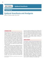
Pacing wire
fracture
Figure 7.3 Chest radiograph showing pacing wire fracture in mid-right atrium (arrowed).
Bradycardias, Pacing, the ICD, Biventricular Pacing for Heart Failure 315
is a particular possibility with patients who indulge in vigorous arm movements above the head as in the gym or with frequent golf.
Perforation
This is a rare complication of permanent pacing. It sometimes occurs in
patients who are temporarily paced for heart block complicating MI (particularly inferior MI affecting the RV). There may be loss of pacing plus signs and
symptoms of pericarditis.
The diagnosis can be confirmed by measuring the intracardiac electrogram
from the temporary wire. The temporary wire is connected to the V lead of a
standard ECG machine. With impaction against the RV wall there should be
an endocardial potential of 1.5–8 mV. This is lost with perforation and ST
depression and T-wave inversion are recorded (Figure 7.4). Repositioning is
necessary.
Battery Failure
Each permanent pacemaker has its own end-of-life characteristics. Premature
battery failure has been a problem with some lithium cell designs. Several
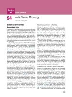
Figure 7.4 Endocardial recording from a pacemaker wire. Top strip shows satisfactory injury
current (ST elevation) as wire impacts against RV endocardium. Bottom strip shows loss of
injury current as a result of perforation.
316 Chapter 7
factors other than cell design may lead to early battery failure, some of which
may be avoided, e.g.:
• low lead impedance with large electrode tip
• wide pulse width
• constant pacemaker use or fast pacing rate
• complex circuitry in automatic pacemakers with two sensing and two
pacing circuits (DDD units); recent units have incorporated microprocessors
that drain current.
Thus the choice of electrode is important. If a pacemaker with hysteresis
mode is available, the takeover rate may be set lower than the basic pacing
rate, conserving battery life. Generally the more complex the pacemaker, the
shorter the expected battery life.
A pacemaker may have its battery life prolonged by reducing rate, pulse
width and output. However, reducing pulse width or output voltage should
not be performed until enough time has elapsed from implantation to allow
for the establishment of the chronic threshold (e.g. 3 months).
The end of life of most pacemaker batteries is indicated by:
• slowing of the basic pacing rate
• increasing pulse width
• decreasing output voltage.
Regular follow-up at a pacing clinic is necessary to determine the time for
elective pacemaker change. Telemetry may help in some areas.
EMG Inhibition (see Figure 7.6)
Electromyographic voltage (e.g. from use of the pectoral muscles) may be of
sufficient strength to be sensed by the permanent pacemaker, cause it to be
inhibited and hence fail to pace the ventricle. It may exceptionally cause
syncope when it is obviously self-limiting. In right-handed patients it is preferable to put the permanent unit on the left side. It is not a problem when a
bipolar wire is used and hence does not occur with temporary pacing systems,
or most modern permanent pacing systems where bipolar pacing can be
programmed. If it does occur in a unipolar system the problem may be
overcome by:
• waiting until any effusion around the unit has resolved
• reprogramming the unit to reduced sensitivity VOO (fixed rate ventricular
pacing) mode
• placing a non-conducting ‘boot’ around the pacemaker
• converting the system to a bipolar system with a new wire.
Sensing Failure
The pacemaker fails to notice an intrinsic cardiac impulse and is not inhibited.
This may be because the R wave of the intrinsic ECG is too small, the slew
Bradycardias, Pacing, the ICD, Biventricular Pacing for Heart Failure 317
rate is too slow or the pacing unit is too insensitive. In temporary pacing this
may be a problem in MI (with reduction in or loss of R waves), resulting in
stimulus-on-T phenomenon. The use of a subcutaneous indifferent electrode
as the second pole may help avoid this.
In permanent pacing the sensitivity of the unit may be changed in some
programmable units (e.g. R-wave sensitivity increased from 2 mV to 10 mV).
A porous tip electrode may offer better sensing capabilities.
False Inhibition (Oversensing) (Figures 7.5 and 7.6)
This is inhibition of the pacemaker by an electrical signal other than by the R
wave. EMG inhibition is an example. It may also occur with spurious signals
Figure 7.5 Examples of pacing ECGs.
318 Chapter 7
Figure 7.6 Common pacing problems (see also Figure 16.2).
Bradycardias, Pacing, the ICD, Biventricular Pacing for Heart Failure 319
from electrode fracture, or inadequate contacts or bad connections to the
internal or external unit. Occasionally, a large T-wave voltage may inhibit the
unit. Electromagnetic interference (e.g. leak from microwave ovens) is another
possibility. This used to cause false inhibition of early permanent pacing units,
but is not a problem now.
Complications of Wire Insertion
Pneumothorax
Following insertion of a pacing wire, the patient should have a chest radiograph to check the wire position and to exclude a pneumothorax.
Infection
Antibiotic prophylaxis is not required for temporary pacing and is indicated
only for clinical reasons. After insertion the wire should be anchored with silk
sutures to avoid movement and the entry site should be covered with a sterile
transparent dressing. If a patient with a temporary wire develops a swinging
pyrexia, this is probably the result of a staphylococcal septicaemia. Blood
cultures should be taken, the patient started on intravenous flucloxacillin
and gentamicin, and the temporary wire removed after a second wire has
been put in from the other side (assuming that temporary pacing is still
necessary).
Prophylactic antibiotics have been shown to help prevent permanent pacemaker infection. The simplest regimen is to give the patient flucloxacillin 1 g
i.v. just before the procedure itself. No further antibiotics are necessary. If the
patient has a prosthetic heart valve then the skin may well be colonized by
methicillin-resistant staphylococci and teicoplanin 400–800 mg i.v. and gentamicin 80–120 mg should be used (dosage dependent on renal function).
Once a permanent unit has been infected (e.g. extrusion of a corner of a box
through ulcerated skin), it should be removed, together with the wire (if possible). There is no point in trying to rescue the situation with antibiotics and
resuturing. A new system should be implanted on the other side.
Haemorrhage
This uncommon complication may result from puncture of the subclavian
artery with a haemothorax or widening mediastinum features appearing
on the chest radiograph. The subclavian artery lies posterior to the vein,
and arterial puncture occurs if the entry site is too posterior (supraclavicular
approach) or if the needle is directed too posteriorly (supra- and infraclavicular approach). Usually needle puncture of the subclavian artery does
not result in complications if the clotting screen is normal. Aspirin
and/or clopidogrel should also be stopped if possible 3–4 days before
implantation.
In elective permanent pacing, if the patient is on anticoagulants, these
should be discontinued where possible to allow the INR/prothrombin time
ratio to fall to ≤1.5 : 1. After box implantation heparin use will cause a
320 Chapter 7
haematoma around the box and warfarin should be restarted the evening of
the implant rather than continuing with heparin.
Thrombophlebitis, Subclavian Vein Thrombosis
This is usually only a problem with median cubital vein entry site, which
should be avoided where at all possible. Temporary pacing from the femoral
vein (other than at formal cardiac catheterization) should be avoided because
of the risk of infection and deep vein thrombosis. Very occasionally a subclavian vein thrombosis occurs with permanent pacing. Collateral veins develop
and dilate around the shoulder and the affected arm may become a little
swollen. If caught early enough (within the first 2 or 3 days) thrombolysis
given intravenously through the affected arm should be tried followed by
formal anticoagulation with heparin and then warfarin.
SVC Stenosis
This is fortunately a rare complication occurring at the junction of the innominate vein to the SVC, caused by the pressure of the pacing wires on the wall
of the vessel as they turn the corner into the SVC. It can be dealt with by
balloon dilatation (Figures 7.7 and 7.8). Stenting of the SVC has also been
Figure 7.7 Superior vena caval stenosis (arrowed) caused by pacing wires: right anterior and
left anterior oblique views. Note no reflux up innominate vein. Previous aortic xenograft valve
replacement.
Bradycardias, Pacing, the ICD, Biventricular Pacing for Heart Failure 321
Figure 7.8 Balloon dilatation of superior vena caval stenosis: the tight stenosis indents the
balloon even high pressure (arrowed). Right panel: final result. Mild residual tubular narrowing.
successful for this complication and the stent does not seem to harm the wire
insulation – possibly because the wires have become endothelialized.
Brachial Plexus Injury
This is rare and occurs also with the entry site being too posterior. If the needle
track is kept strictly subclavicular, this will be avoided.
Thoracic Duct Injury
This is rare. The main thoracic duct drains into the junction of the left subclavian and left internal jugular veins. Temporary pacing via the right subclavian
vein should therefore be attempted first.
Arrhythmias
Manipulation of the wire in the right atrium may produce atrial ectopics,
atrial tachycardia or AF. Manipulation in the right ventricle (especially postinfarction) may produce VT or VF. If the RV is very irritable, a lidocaine infusion should be set up (starting with 100 mg i.v. stat and 4 mg/min). Atrial
arrhythmias are usually transient and of less serious consequence, especially
if the wire is being inserted for complete AV block.
322 Chapter 7
Pacemaker Box Migration
With modern light generators this is now an unusual complication. Generators can slip from a routine prepectoral position into the axilla and become
uncomfortable. In this case repositioning of the unit may be necessary. The
problem is avoided by implanting the box beneath pectoralis major in thin
people.
Difficulties with Vein Access
Failure to Find a Subclavian Vein
This may be a result of the needle direction being too posterior. A few manoeuvres may help: keep the needle direction horizontal initially. Try bending the
needle at the hub slightly so that the needle points upwards/anteriorly.
Remove the patient’s pillow briefly to help open the gap between the clavicle
and the rib. Ask an assistant to pull on the ipsilateral arm while the subclavian
vein puncture is made. Inject dilute contrast through an arm vein to show up
the subclavian vein and freeze the image on a slave screen. Finally, if all this
fails, wire the subclavian vein retrogradely from the femoral vein and use the
wire as a marker.
Upgrading a Pacing System
This can be difficult because the existing lead has already possibly used up
the cephalic vein. Subclavian vein puncture is necessary under screening.
Keep the needle close to and parallel with the existing wire to access the
subclavian. The fear is injury to the existing wire’s insulation with the needle,
but fortunately this is unusual! If the subclavian or innominate veins is thrombosed switch to the other side with a new system.
Left SVC Draining into Coronary Sinus
This uncommon anomaly usually comes as an unpleasant surprise after successful subclavian or cephalic vein cannulation. The wire tracks down the left
side of the mediastinum reaching the right atrium via a dilated coronary
sinus. If this problem is encountered, switch to a long lead (64 cm rather than
the conventional 58 cm) with an active fixation (screw-in) tip. Once in the right
atrium, advance the lead and withdraw the stylet a few inches so that the lead
loops over itself into an ‘α’ formation and the tip can be negotiated down
into the RV apex (Figure 7.9).
Pacemaker Implantation in Patients on Anticoagulants
Pacemaker implantation should be performed with the INR <1.5 if possible,
and delayed if the INR >2.0. If the patient is taking warfarin only for AF, the
warfarin can be stopped 4–5 days before implantation, without the need
for additional heparin cover. The warfarin is restarted the night of the
procedure.
If the patient is on warfarin for a mechanical valve replacement,
heparin cover is advised even though the embolic risk is small for the time
Bradycardias, Pacing, the ICD, Biventricular Pacing for Heart Failure 323
Pacing wire
in left SVC
Figure 7.9 Permanent pacing (VVI unit) via left SVC. Previous aortic Starr–Edwards aortic valve
replacement and failed pacing via right SVC. The left SVC pacing wire reaches the right atrium
via characteristic course down a dilated coronary sinus and is looped over in the right atrium
to reach RV apex.
warfarin is stopped. Patients are told to stop warfarin and then admitted for
heparin injections once the INR falls below 2.5 (e.g. Fragmin 120 U/kg s.c.
twice daily). The low-molecular-weight heparin is stopped the morning of the
procedure and warfarin restarted with a loading dose (e.g. twice the maintenance dose) the night of the implantation. Heparin should not be given
immediately postoperatively as a wound haematoma is likely. If the INR
remains >2.5 48 h after implantation, the heparin could be restarted until the
INR rises >2.5.
7.3 Glossary of Pacing Terms in Common Use
Automatic Interval (Basic Interval)
This is the stimulus–stimulus interval during regular pacing.
Bipolar Pacing System
Most temporary wires use a bipolar pacing wire with two ring electrodes.
The proximal ring electrode (approximately 1 cm from electrode tip) is the
anode, and the distal (tip) electrode the cathode. Sometimes the position of
the anode may be higher up the wire (e.g. in the SVC). The pacing spike is
small on the surface ECG. Bipolar wires are also available for permanent
pacing and are used routinely now. A permanent bipolar system is immune
to external signals (see Section 7.9). In addition the bipolar system has the
324 Chapter 7
advantage that the pacing unit will continue to pace the heart when it has
been explanted (if still attached to the wire), which greatly facilitates the box
change procedure.
Blanking Period
This is the time interval after a pacing impulse during which the pacemaker
is insensitive to signals from the heart or from the other channel (avoiding
cross-talk).
Chronotropic Incompetence
This is the inability of the heart to increase its rate in response to exercise or
metabolic demand.
Committed
This is a dual-chamber pacing system in which the delivery of an atrial stimulus forces the delivery of a ventricular stimulus after a programmed AV
delay.
Cross-talk
This happens in DDD units sensing of electronic events from one channel by
the other channel, e.g. an atrial stimulus sensed by the ventricular channel
resulting in dangerous inhibition of the ventricular impulse. This is avoided
by the blanking period (see Figure 7.13).
Demand Pacing (Inhibited)
Unlike the fixed-rate mode, spontaneous cardiac activity is sensed and inhibits the pacemaker, which fires a stimulus only after a pre-set interval if no
further impulse is sensed. Thus pacing is inhibited by sensed impulses (atrial
or ventricular, see codes in Section 7.5).
Entrance Block
The failure of a pacemaker to sense cardiac events because the sensitivity of
the pacemaker is too low, the signals are of too low an amplitude or the lead
is fractured (see Figure 7.3).
Epicardial System
This is pacing wires attached to the epicardium either at thoracotomy or by
subxiphoid route. The permanent unit is usually intra-abdominal (beneath
the rectus muscle and extraperitoneal). It is used in the following:
• Recurrent failure of endocardial systems (infection, exit block, etc.)
• Small children where rapid growth makes transvenous pacing difficult (see
Section 7.12)
• Heart block developing during cardiac surgery
• Tricuspid mechanical valve prosthesis; the only exception is a tricuspid
Starr–Edwards valve (ball and cage) which can be crossed with a pacing wire
Bradycardias, Pacing, the ICD, Biventricular Pacing for Heart Failure 325
Figure 7.10 Chest radiograph: P/A and right lateral. Triple valve replacement. Starr–Edwards
valves. Pacemaker wire through tricuspid Starr valve cage.
(Figure 7.10); the wire obstructs complete ball closure resulting in mild tricuspid regurgitation.
Epicardial systems tend to be less reliable in the long term. Wire displacement and fracture may occur as a result of kinking and vigorous movement.
The need for epicardial pacing has diminished with the introduction of LV
leads implanted via the coronary sinus. (see Biventricular pacing – Figures
7.17–7.19).
Escape Interval
The interval between a spontaneous cardiac impulse that is sensed and the
next pacing stimulus. This is usually the same as the automatic pacing interval
unless the pacemaker is programmed to hysteresis mode, in which case the
escape interval is longer than the automatic interval.
Exit Block
This is failure of pacing caused by problems at the wire tip such as a fibrotic
reaction preventing transmission of the electrical impulse from wire to myocardial cells (see Figure 7.2).
Fixed-rate Pacing
This is constant stimulation of the heart at a fixed rate not influenced by
spontaneous cardiac activity.
Hysteresis
This is when the takeover rate of the pacemaker is lower than the pacing rate,
e.g. a pacemaker with a pacing rate of 72 beats/min and hysteresis mode set
326 Chapter 7
at 60 beats/min will not start pacing until the patient’s heart rate falls to
<60 beats/min, then the pacing rate jumps to 72 beats/min. Patients may
notice the abrupt change in rate, but it conserves battery life.
Lead Impedance
This is a vital factor in battery life. It includes the electrical resistance of the
electrode itself plus the impedance of the electrode tip–tissue interface. The
size of the electrode tip influences impedance of the wire (the larger the tip,
the lower the impedance). Low-impedance wires result in early battery depletion. Average lead impedance is 510 Ω. Development of newer electrodes has
resulted in smaller electrode tips (initially 12 or 14 mm2 now down to
4 mm2).
Magnet Rate
Application of a magnet over some VVI units converts them to a faster (fixed)
pacing rate. This is used to test battery life and satisfactory pacing if there is
competition at a slower demand rate.
Missing
This is the term used to denote failure of a pacing stimulus to capture and
depolarize atrial or ventricular myocardium. It may be caused by incorrect
lead positioning, too low an output voltage or too high a myocardial threshold. Initial management is to increase pacing voltage if a temporary system,
and then reposition the wire if this is not successful. Missing with a permanent
system cannot be ignored. The unit must be removed, the wire threshold
tested and either repositioned or changed.
Mode Switching
This is the ability of a dual chamber pacemaker to switch pacing modes. When
a patient with paroxysmal AF or atrial tachycardia goes into AF or SVT the
pacemaker switches to VVIR mode, thus avoiding atrial tracking with fast
ventricular rates, e.g. rates of >175 for 5–10 cycles or even less in some units
will trigger the mode switch. The unit switches back to DDDR mode when
sinus rhythm reappears or the atrial rate falls. In patients with regular atrial
arrhythmias, some units can mode switch to DDIR mode, thus avoiding atrial
tracking.
Myopotential (EMG) Inhibition (see Figure 7.6)
This is an electrical signal from skeletal muscle (usually pectoral), which is
sensed by the pacemaker, incorrectly interpreted as cardiac in origin and
falsely inhibits the pacemaker impulse.
Non-committed
This is a dual-chamber pacemaker in which the sensing of ventricular activity
during the AV interval can inhibit the delivery of a ventricular impulse.
Bradycardias, Pacing, the ICD, Biventricular Pacing for Heart Failure 327
Oversensing (False Inhibition) (see Figures 7.5 and 7.6)
This is inhibition of the pacemaker by non-physiological electromagnetic
interference or physiological myopotential signals. In this instance pacemaker
sensitivity must be reprogrammed to a lower setting.
Paired Pacing
A double impulse fired in rapid succession to the ventricle results in an
increased force of contraction, but a much greater myocardial oxygen consumption and a risk of inducing VT. It is not used in clinical pacing.
Pulse Width/Pulse Duration
This is the duration of the pacing stimulus (usually between 0.5 and 1.0 ms).
The broader pulse width may capture the ventricle and pace it when narrower
pulse widths fail, but this will drain more current and shorten battery life of
permanent units. The same applies to atrial pacing.
Rate-responsive Pacing (Adaptive Rate Pacing)
This is a permanent pacing system in which the pacemaker speeds up and
slows down in response to certain physiological stimuli. It may be singlechamber (AAIR or VVIR) or dual-chamber (DDDR) (see Section 7.5).
Relative Threshold
Some pacing units have an analysable threshold once implanted permanently.
The relative threshold is the minimum percentage of total available voltage
required to pace the heart. Thus a relative threshold of 25% is with maximum
unit voltage of, say, 5.2 V is 1.3 V.
Sequential Pacing
This is pacing of the atrium followed at a pre-set interval by pacing of the
ventricle. This allows physiological atrial transport (see Section 7.6).
Slew Rate
This is the rate of rise of the endocardial potential (dV/dt). Potentials with a
low slew rate may not be sensed.
Telemetry
This is a pacemaker facility to transmit a radiofrequency signal containing
information about battery life, programmable functions, frequency of pacemaker use, etc.
Tilt Testing
This is used to provoke syncope in patients with possible cardioneurogenic
syncope. Patients lie flat for 20–30 min and are then tilted head-up to 60° for
45 min. Continuous ECG and blood pressure recordings (ideally from a radial
artery line) are needed.
328 Chapter 7
Triggered Pacing (see Figure 7.5)
A sensed spontaneous R wave results in immediate pacing stimulus fired into
the R wave (the heart obviously refractory and not paced). Triggered pacing
units have a built-in refractory period to protect against fast electrical interference inducing VT. Ventricular triggered pacing may be used:
• to avoid EMG inhibition
• when a temporary wire is inserted to cover a failing permanent unit. Stimuli
from the failing implanted unit trigger the external unit to fire an impulse. This
falls in the absolute refractory period (if the internal unit’s impulse depolarized the heart) or alternatively paces the heart if the internal/permanent unit
impulse fails to depolarize the heart. It is thus a fail-safe mechanism.
Unipolar Pacing System
The earliest permanent units were unipolar: using the pacing box as the anode
(+) and the pacing wire as the cathode (–). The pacing spike was large on the
surface ECG. Bipolar pacing leads are now used routinely with a distal tip
electrode (cathode) and the anode electrode about 1 cm proximal to the tip.
The advantage of this system is that it avoids EMG inhibition.
Voltage Threshold
This is the minimum voltage that will pace the heart.
7.4 Permanent Pacing for Bradyarrhythmias
There has been an enormous increase in pacemaker technology since the first
pacemaker was implanted by the Karolinska Hospital team in 1958. Permanent pacing is one of the most cost-effective forms of treatment in the whole
of medicine. Numbers of implants are increasing, but the implant rate in the
UK is among the lowest in Europe, resulting partly from the lack of pacing
centres and partly from the low referral rate for pacing. Data from the HRUK
registry (see Appendix 5) show a gradual increase in number of pacemakers
implanted in the UK with an increase in dual chamber and rate responsive
systems (Table 7.1).
Indications for Permanent Pacing
These vary from country to country, but certain definite categories are
recognized.
Chronic Complete AV Block with Stokes–Adams Episodes
This is usually the result of central bundle-branch fibrosis (Lenegre’s disease),
often with normal coronary arteries in the older group. The QRS complex is
wide. Pacing should abolish symptoms and prolong life (1-year mortality rate
of 35–50% unpaced, 5% paced). Symptoms other than frank syncope, which
may result from AV block, include giddiness, transient amnesia and misdiagnosed epilepsy.
Bradycardias, Pacing, the ICD, Biventricular Pacing for Heart Failure 329
Table 7.1 The changing practice of pacing in the UK
Parameter
1989
1998
2002
2005
Pacing centres (n)
Patients paced (n)
Implants/million population (n)
VVI units (%)
VVIR units (%)
DDD units (%)
DDDR units (%)
AAIR units (%)
138
10 500
178
79
2.5
16
1
0.36
177
24 000
406
34.9
14.1
36.9
11.8
0.71
164
27 737
466
18
19
37
25
1
191
36 303
603
15
24
27
27
1
In the younger age group coronary artery disease may be an additional
prognostic factor.
Chronic Complete AV Block with No Symptoms
This is a smaller group of patients who should also be paced because life
expectancy is increased, and the first Stokes–Adams episode may be fatal:
ECG monitoring for 24 hours usually reveals very slow idioventricular rhythm
at night (e.g. <20 beats/min).
Congenital Complete AV Block (see Figure 7.1)
In this condition the level of block is higher up in the His bundle or AV node.
The QRS complex is narrow and the idioventricular rhythm faster, and it may
respond slightly to exercise or other autonomic stimuli. Asymptomatic children may survive into adult life, when a permanent transvenous system is
easier to insert. Indications for pacing in congenital complete AV block are:
• development of any rate-related symptoms
• wide QRS
• other cardiac lesions and cardiac surgery
• early presentation
• failure of AV node to respond to exercise (‘lazy junction’), etc.
• 24-hour monitoring evidence of functional exit block or paroxysmal
tachyarrhythmias
• a daytime mean functional rate <50/min: because this carries a higher longterm risk of syncope and sudden death.
Mobitz Type II AV Block (see Figure 7.1 and Chapter 16, Figure 16.5)
This type of AV block is characterized by a constant PR interval and the
sudden failure of conduction of an atrial impulse through the AV node. There
is a high incidence of complete AV block developing and patients with this
type of AV block should be paced permanently.
It should be noted that Wenckebach type I AV block is not an indication
for permanent pacing. It may result from high vagal tone in athletes or
330 Chapter 7
children, and may be a transient phenomenon in acute inferior infarction
(involving the AV nodal artery). It may result from drug toxicity (digoxin,
β blockade, verapamil). Generally it is a benign, transient rhythm
disturbance.
Post-MI
After inferior infarction, second- or third-degree AV block is normally transient, and permanent pacing does not need to be considered for 2–3 weeks
post-infarct.
After anterior infarction, complete AV block usually represents massive
septal necrosis, and mortality from LVF is high. Persistent complete AV block
is permanently paced. More difficult is an AV block that regresses during
hospital stay. This is still a subject for debate, but 24-hour Holter monitoring
may help identify those at risk who need permanent pacing. The ventricular
myocardium is often very irritable in the post-infarct period and if possible
permanent pacing should be avoided in the first 3–4 weeks.
Chronic Bundle-branch Block
Early work to suggest that His bundle electrograms (Figure 7.16) would identify patients at risk has not been substantiated. Theoretically a prolonged H–V
interval in the presence of bifascicular block would indicate the third fascicle
at risk. However, this does not seem to be prognostically useful. The incidence
of chronic asymptomatic patients with bifascicular block developing complete
AV block is low. It does not seem to be precipitated by general anaesthesia.
Again 24-hour Holter monitoring may be helpful. Generally, asymptomatic
patients with bifascicular block do not merit permanent pacing. Pacing is
indicated for patients with symptoms plus bifascicular block, e.g. symptoms
plus:
• RBBB + LAHB
bifascicular disease (see Figures 16.7 and 16.8)
• RBBB + LPHB
}
• RBBB with alternating LAHB/LPHB
• LBBB with alternating RBBB
• LBBB + long PR interval
}
‘trifascicular’ disease
Sick Sinus Syndrome
Sick sinus syndrome (SSS) is also known as sinoatrial disease, tachycardia–
bradycardia syndrome or generalized conduction system disease. Although
primarily involving the sinus node and atrial myocardium, it may develop
into a condition including AV node disease, or even be associated with a cardiomyopathy. Systemic emboli are a recognized complication (possibly related
to prolonged periods of sinus arrest).
Common ECG abnormalities include the following (often switching from
one to another) (Figure 7.11):
• Sinus arrest: chronic or paroxysmal
Bradycardias, Pacing, the ICD, Biventricular Pacing for Heart Failure 331
Figure 7.11 Sinoatrial disease: segments of a single 24-hour monitored ECG in a patient with
this condition (also known as sick sinus syndrome). The ECG shows episodes of wandering
atrial pacemaker and sinus arrest (first line), junctional escape rhythm and AF (second line),
sinus arrest (third line), sinus rhythm and supraventricular tachycardia (fourth line) and
junctional bradycardia moving into sinus rhythm (fifth line).
• Sinus bradycardia: not necessarily responding to effort or atropine
• Sinus exit block
• Paroxysmal atrial tachycardia, atrial flutter, AF
• Carotid sinus hypersensitivity
• AV block: usually in the older age group, who may have AF with complete
AV block and a slow idioventricular rhythm.
Permanent pacing in SSS does not prolong life. The following are the indications for permanent pacing:
• Symptoms with a documented bradycardia
• Symptoms caused by drug-induced bradycardia (used to control the
tachyarrhythmias). AAI pacing will maintain atrial transport while AV nodal
conduction is still normal. However, the development of AV block may require
a change to DDDR pacing (see Section 7.6).
332 Chapter 7
7.5 Pacemaker Codes
With increasing complexity of permanent pacemakers, codes have been
developed to enable operators to identify the capabilities of individual
units.
The initial three-letter code was introduced by Parsonnet in 1974 and is
currently in use on the European Pacemaker card. This has been agreed by
the International Association of Pacemaker Manufacturers. The four-letter
code is now in general use, but already likely to be superseded by a five-letter
code, to cope with facilities available on newer programmable units. A sixth
letter may one day be included to cope with telemetric capabilities.
As Table 7.2 shows, the first letter of the code always relates to the chamber
paced, the second to the chamber sensed. The third letter indicates the pacemaker response to the sensed impulse. Formerly, this third letter was replaced
by a ‘fraction’, e.g. T/I or TI/I, because the more complex pacemaker
responded in different ways to stimuli from atrium and ventricle.
The most frequently used pacemaker in the UK has the code DDD (37% of
UK implants in 1998 – see Section 7.6).
Individual Pacing Codes
These are shown diagrammatically with a schematic ECG alongside each.
VOO
This is fixed-rate ventricular pacing only, and is now rarely used, i.e. ventricular pacing, no sensing and no response. The pacemaker is not inhibited
by spontaneous ventricular impulses, and there is a small risk of stimulus on
T phenomenon causing ventricular tachycardia.
VVI
This is ventricular pacing that is inhibited by sensed ventricular impulses. It
is the unit of choice in patients with AV block and AF, and SSS with atrial
paralysis.
Bradycardias, Pacing, the ICD, Biventricular Pacing for Heart Failure 333
However, patients with AV block and persistent sinus node function will lose
atrial contribution to ventricular filling because often the atria contract against
closed AV valves. There will be cannon waves in the JVP, and intermittent
reversal of atrial flow. Retrograde AV conduction compounds the problem.
Programmable VVI units may partly overcome this by being programmed
to a lower rate, or with hysteresis.
AAI
This is only atrial pacing that is inhibited by sensed P waves. This type of
pacemaker is used in patients with SSS who have normal AV node function.
(It does not matter if they have retrograde AV conduction.) It may be used in
patients with profound sinus bradycardia or in drug-induced sinus bradycardia (in the SSS) (see Figure 16.6). Atrial transport is preserved.
However, this pacing relies on normal AV node function, and patients with
SSS may develop abnormalities in AV conduction after the unit has been
implanted (≤30% in one series). Also it is obviously unsuitable for patients
with SSS and intermittent AF, which may develop after the unit has been
implanted.
The are following contraindications to AAI pacing:
• AV block or Wenckebach block with atrial pacing up to 150/min
• Bifascicular block on 12-lead ECG
• Atrial flutter, AF or paralysis
• Carotid sinus syndrome
• H–V interval > 55 ms or prolonging with high atrial rates.
Thus His bundle electrograms and atrial pacing studies are necessary before
choosing to implant an AAI unit.
AOO
This is asynchronous atrial pacing. Rarely used except in patient-activated
bursts to overdrive atrial tachycardias. In using rapid atrial stimulation bursts, it
is important to be certain that there is no pre-excitation pathway to the
ventricle.
334 Chapter 7
VAT
This is ventricular pacing triggered by a sensed atrial impulse. Two leads are
required. This is P-wave synchronous pacing with normal sinus node function. It cannot be used in patients with atrial dysrhythmias, AF or atrial
flutter.
Its major disadvantage is that it does not sense ventricular impulses,
and hence will compete with spontaneous ventricular activity. If the patient
has frequent ventricular ectopics there is the risk of stimulus-on-T
phenomenon.
It is the simplest way of preserving atrial transport in patients with AV
block (se Chapter 16, Figure 16.6) but rarely used now.
DVI
This is atrial and ventricular pacing, but only spontaneous ventricular
activity is sensed. Spontaneous atrial activity is ignored. Two leads are
required. After a spontaneous ventricular impulse is sensed the pacemaker
resets to one V–A interval and fires an atrial impulse, followed by a ventricular impulse. Spontaneous P waves occurring within this V–A interval are not
sensed.
It can be used in complete AV block or sinus bradycardia. It cannot be used
in AF. Although atrial synchrony is maintained at a basal rate, it will not
follow an increase in sinus rate with exercise, and competes with atrial rates
faster than the pacemaker rate. It is useful in patients with retrograde VA
conduction.