Ebook Ultrasound-Guided liver surgery (edition): Part 2
Bạn đang xem bản rút gọn của tài liệu. Xem và tải ngay bản đầy đủ của tài liệu tại đây (31.76 MB, 91 trang )
Part IV
Liver Transplantation
Liver Transplantation from Deceased
Donors
10
Matteo Cescon, Fabio Piscaglia, Alessandro Cucchetti,
and Antonio Daniele Pinna
Doppler ultrasonography (US) provides an accurate assessment of the hepatic vasculature in liver
transplantation (LT). It can be performed perioperatively or at the bedside. The evaluation of
the hepatic vessels includes color and spectral
Doppler analysis. ColorDoppler provides information regarding the presence and direction of
flow, as well as the location of turbulent flow in a
post-stenotic segment. Spectral analysis describes
the direction, velocity, and phasicity of flow.
10.1
Hepatic Artery Complications
There are several possible sites of hepatic artery
(HA) anastomosis. In orthotopic whole LT, the
most frequent anastomosis is between the donor
celiac or common HA, and the recipient HA at
M. Cescon (&) Á F. Piscaglia Á A. Cucchetti Á
A. D. Pinna
General Surgery and Transplantation Unit,
Department of Medical and Surgical Sciences,
University of Bologna,
Via Massarenti 9, 40138 Bologna, Italy
e-mail:
F. Piscaglia
e-mail:
A. Cucchetti
e-mail:
A. D. Pinna
e-mail:
either the bifurcation into left and right hepatic
arteries or the origin of the gastroduodenal
artery. When the recipient HA cannot be used,
the anastomosis can be performed on the recipient aorta with a donor artery interposition
graft, on the recipient splenic artery or on an
accessory HA. The presence of a donor accessory artery requires a second anastomosis. In
split LT, the anastomosis is variably performed
between the donor right, left, proper or common
HA, and the recipient right, left, proper or
common HA, with or without interposition
vascular grafts. Knowledge of the type of anastomosis is important because stenosis frequently
occurs at this site. HA complications include
thrombosis, stenosis, and pseudoaneurysm. Biliary ischemia is often the consequence of HA
thrombosis or stenosis [1, 2], with development
of non-anastomotic biliary strictures or leaks.
On Doppler US, the normal HA has a low
resistance waveform with continuous diastolic
flow and a resistance index (RI, defined as peak
systolic velocity minus end-diastolic velocity,
all divided by peak systolic velocity) ranging
between 0.60 and 0.80. The systolic peak has a
rapid, almost vertical shape, with an early peak
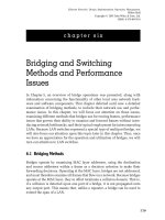
and a highest peak (Fig. 10.1). For the measurement of systolic acceleration time, the early
peak is to be used. For the measurement of RI,
the highest peak is to be used (Figs. 10.2 and
10.3). An RI lower than 0.50 in any hepatic
arterial vessel indicates HA thrombosis or
stenosis, with a sensitivity of 60 % and a
specificity of 77 % [3, 4]. A prolonged systolic
G. Torzilli (ed.), Ultrasound-Guided Liver Surgery,
DOI: 10.1007/978-88-470-5510-0_10, Ó Springer-Verlag Italia 2014
185
186
Fig. 10.1 Arterial Doppler ultrasound waveform showing both early and highest systolic peaks (early and
highest systolic peaks may be coincident or not coincident, as represented in this instance)
acceleration time ([0.08 s) is also predictive of
stenosis, with a sensitivity/specificity of 53 and
86 %, respectively [3, 4]. A low RI and/or a long
acceleration determine the tardus parvus waveform (Figs. 10.4, 10.5, 10.6, 10.7, 10.8). At the
site of stenosis, an increased peak systolic
velocity ([200 cm/s) can be detected. This is the
most specific sign of hepatic arterial stenosis
and, if present, is predictive in 96 % of the cases
[3, 4].
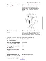
Fig. 10.3 Normal
Doppler US waveform of
the right hepatic artery
detected at its entrance into
the right liver lobe,
alongside and anteriorly to
the right portal branch. The
systolic acceleration time
is clearly normal
(corresponding to a rapid
rise of systolic velocity)
and the RI is not decreased,
namely the end diastolic
velocity is relatively low
with respect to peak
velocity (numeric data not
measured in this image)
M. Cescon et al.
Fig. 10.2 US arterial wave with representation of early
and highest peaks. For the measurement of systolic
acceleration time, the early peak is to be used. For the
measurement of Resistance Index (RI, i.e., systolic
velocity minus end-diastolic velocity/systolic velocity),
the highest peak is to be used
10.1.1 Thrombosis
Absent arterial flow in all arteries on a technically adequate Doppler imaging study is nearly
always indicative of thrombosis. False positives
may occur due to severe hepatic edema,
10
Liver Transplantation from Deceased Donors
187
Fig. 10.4 A case of cholangitis with mild bile duct dilatation and inhomogeneous liver echotexture, particularly in
the left lobe, visualized through a subcostal epigastric scan. The patient presented with fever and malaise
systemic hypotension, or in a suboptimal ultrasound study. Reduced flow, whether secondary
to spasm or to low cardiac output, can also cause
non visualization of flow at Doppler US. A loss
of diastolic flow or diastolic flow reversal has
been suggested as a sign of impending thrombosis [5, 6], especially if it occurs in the main
HA.
Fig. 10.5 Same case as Fig. 10.4. Right hepatic artery
was detectable at both color and pulsed wave Doppler,
but showed a ‘‘tardus parvus’’ flow trace, corresponding
to a low RI (below 0.50, in this instance RI = 0.47) and
prolonged systolic acceleration time (over 100 ms, in
this instance 128 ms; data not shown)
188
M. Cescon et al.
Fig. 10.6 Hepatic artery tracing with normal RI (0.60) but prolonged acceleration time (T1 = 200 ms) detected
12 years after LT
Fig. 10.7 Same case as Fig. 10.6. Angio CT shows elongated narrowing of the proper hepatic artery due to
atherosclerosis (yellow frame)
Microbubble contrast material-enhanced US
may help to improve flow visualization in the
HA [7]. In patients in whom no flow is identified
in the HA, angiography, computed tomography
(CT), or magnetic resonance (MR) angiography
are usually required to definitely diagnose
10
Liver Transplantation from Deceased Donors
189
Fig. 10.8 A case of kinking of the hepatic artery shown
by angiography (on the left) determining a hemodynamic
stenosis indicated by Doppler US (on the right), with
downstream tardus parvus waveform (RI = 0.40), and
markedly turbulent and accelerated flow at the site of
kinking (peak flow velocity approximately 3 m/s)
thrombosis. The treatment of HA thrombosis
usually consists of emergent thrombectomy or
retransplantation.
10.1.3 Pseudoaneurysms
10.1.2 Stenosis
HA stenosis occurs in 2–11 % of transplantations [8, 9]. The most common site of stenosis is
the anastomosis, which is often difficult to detect
by US, being frequently obscured by bowel. In
the very early postoperative period (\72 h after
transplantation), increased HA RI ([0.8) is frequently observed, although it usually returns to
normal within a few days [10]. Increased RI is
associated with fibrotic livers and a prolonged
period of ischemia [10]. HA stenosis may be
treated with percutaneous angioplasty or surgical intervention [11].
HA pseudoaneurysm is an uncommon complication and can be classified as either extrahepatic
or intrahepatic. Extrahepatic pseudoaneurysm
most commonly occurs at the arterial anastomosis or arises as a complication of angioplasty,
whereas intrahepatic pseudoaneurysm may result
from percutaneous biopsy, biliary procedures, or
infection [12, 13].
A pseudoaneurysm is identified on US as a
cystic structure in communication with the HA
with a disorganized ‘‘to and fro’’ color and
spectral Doppler pattern as the arterial blood
flows into and out of the pseudoaneurysm
(Fig. 10.9).
US detection of a fluid collection near the
arterial anastomosis requires further evaluation with pulsed Doppler US to rule out
190
M. Cescon et al.
Fig. 10.9 Hepatic artery
aneurysm, close to the
anastomotic site (diameter
of the hepatic
artery = 4 mm, maximum
diameter of the dilated
tract = 12 mm)
pseudoaneurysm. Contrast-enhanced CT demonstrates a focal lesion with central enhancement that follows arterial blood-pool
attenuation. Treatment consists of embolization
for both types of aneurysms, as well as stent
placement or surgical resection for an extrahepatic pseudoaneurysm [13, 14]. A ruptured
intrahepatic pseudoaneurysm can lead to a portal
or biliary fistula.
10.1.4 Arterioportal Fistula
Intrahepatic arterioportal fistula is usually
secondary to liver biopsy of other invasive procedures. On US, the inflowing hepatic arterial RI
will be lower than the contralateral normal
vessel on the opposite side. In addition, reversed
flow in particular portal vein (PV) radicals
(considered a rare finding), arterialized PV
waveform as well as a focus of turbulence with
aliasing at the site of the arterioportal fistula can
also be seen [12, 15–17].
10.2
(Fig. 10.10). In split grafts, the anastomosis is
usually performed between the donor and recipient right or left portal branches. In the case of
preoperative PV thrombosis and/or portal
hypoplasia, PV thrombectomy (Fig. 10.11) and
anastomosis on different recipient sites are possible solutions. In this latter case, the anastomosis can be performed on enlarged tributaries
of the PV, on the superior mesenteric vein
through a donor vascular graft, on the left renal
vein or on the recipient inferior vena cava (IVC)
(cavoportal hemitransposition). PV complications are less common than arterial complications. They occur in 1–13 % of whole
transplantations, and include thrombosis and
stenosis [18]. Technical errors, insufficient
Portal Vein Complications
In orthotopic whole LT, the PV anastomosis is
usually performed in an end-to-end fashion
between the donor and the recipient portal trunks
Fig. 10.10 End-to-end portal vein anastomosis in
orthotopic whole LT
10
Liver Transplantation from Deceased Donors
Fig. 10.11 Thrombectomy for partial occlusion of the
portal vein during LT
thrombectomy, discrepancy between the sizes of
the donor and recipient PVs, hypercoagulable
state, and insufficient flow due to spontaneous
portosystemic shunts are the main causes of
191
Fig. 10.13 Same case as Fig. 10.12. A hemi-portocaval
shunt between the recipient right branch of the portal
vein and the inferior vena cava (IVC) is shown in this
surgical field. The creation of the shunt was mandated
following persistence of graft congestion and excessive
portal flow not withstanding the attempt to resolve this
circulatory abnormality by splenic artery ligation
Fig. 10.12 Portal flow of 25 cm/s, associated with congestion of a left lobe graft (segments II–III), a few minutes
after portal reperfusion, due to portal hyperflow in a small-for-size graft
192
M. Cescon et al.
Fig. 10.14 Same case as Figs. 10.12 and 10.13, but after creation of the hemi-portocaval shunt. The portal flow
decreased to normal values and became phasic with caval flow changes related to the cardiac cycle
complications [18]. Intraoperatively, a scarce
portal flow can be increased with ligation of
collaterals of PV or of the left renal vein, in
order to reduce the flow through portosystemic
shunts. Postoperatively, angioplasty, thrombolysis, thrombectomy, redo anastomosis or retransplantation can be required.
In split LT, the use of small-for-size grafts
(especially left-sided grafts) is often associated
with liver congestion and dysfunction. This
condition is attributable to excessive portal flow
in relationship with the reduced hepatic mass,
causing endothelial disruption, and secondarily
parenchymal injury with cholestasis. The portal
flow can be reduced with splenic artery ligation,
splenectomy, or creation of a hemi-portocaval
shunt (Figs. 10.12, 10.13, 10.14).
Fig. 10.15 Visualization of the end-to-end portal vein
anastomosis after LT through an intercostal transcutaneous approach, which appears as white indentations
along the main portal trunk at conventional gray-scale
US (a frame on the right), and not producing any change
in flow velocity, as depicted by color Doppler US
(b frame on the left). In another case, the portal
anastomosis is visualized through a right upper abdominal quadrant subcostal approach (b)
10.2.1 Thrombosis
On US, there is either total absence of flow in the
PV on color Doppler, or a mass filling in a
portion of the PV and partially occluding it.
Contrast-enhanced CT or MR appearance is
c
10
Liver Transplantation from Deceased Donors
193
194
similar. In the acute phase, the vessel is distended. Subsequently, PV tends to narrow and
scar, while the thrombus becomes more echogenic. Hematoma or fluid collections can cause
the PV compression, with symptoms similar to
thrombosis and absence of PV visualization on
US.
M. Cescon et al.
10.3
Inferior Vena Cava and Hepatic
Vein Complications
PV stenosis usually occurs at the anastomosis
[19] (Figs. 10.15, 10.16, 10.17). US findings
include peak anastomotic velocity higher than
125 cm/s or an anastomotic-to-preanastomotic
velocity ratio of 3:1 [20] (Figs. 10.16, 10.17).
Focal narrowing of the PV on US, CT, or MR
may represent discrepancy between donor and
recipient PV vein size, or may indicate a true
stenosis [19].
There are different anastomotic options for the
IVC in orthotopic whole LT. With the conventional technique, the recipient retrohepatic IVC
is removed with the native liver, and the donor
and recipient IVCs are anastomosed superiorly
and inferiorly in an end-to-end fashion
(Fig. 10.18). Otherwise, the recipient IVC can
be preserved. In this case, the so-called ‘‘piggyback’’ technique involves the anastomosis of
the donor IVC to the stump of the main recipient
HVs (left and middle HVs, with or without right
HV) (Figs. 10.19, 10.20). Another technique is
represented by the end-to-side or side-to-side
anastomosis between the donor and the recipient
IVC. In split grafts (Figs. 10.21, 10.22), HVs are
usually anastomosed to the recipient IVC or to
the stump of recipient major HVs. The
Fig. 10.16 Flow disturbance with turbulences (indicated by the aliasing phenomenon, corresponding to the
mixture of blue, yellow, and red colors at color Doppler
in the left frame) at the site of lumen narrowing at the
portal anastomotic site (black arrow, right frame) and
immediately downstream from it. In this instance, a
pulse Doppler flow trace sampling is mandatory to
ascertain whether a focal acceleration occurs
(over 9 3–4 the upstream velocities), suggesting a
hemodynamic stenosis
10.2.2 Stenosis
10
Liver Transplantation from Deceased Donors
Fig. 10.17 Portal vein
flow in the case of
hemodynamic stenosis.
White arrow indicates a
color Doppler pattern of
aliasing (see legend to
Fig. 10.16). Doppler flow
trace on the pre-stenotic
portal trunk (black arrow)
shows low velocity,
whereas at the site of
stenosis a focal aliasing
with flow acceleration
(over 9 4) is demonstrated
(arrowhead)
195
196
M. Cescon et al.
Fig. 10.19 Intraoperative view of piggyback caval
anastomosis
Fig. 10.18 End-to-end inferior IVC anastomosis (longitudinal view)
Fig. 10.20 Piggyback anastomosis between the donor suprahepatic IVC and the cuff of recipient major hepatic veins
(lateral view); hepatic vein (HV)
10
Liver Transplantation from Deceased Donors
197
stump of the donor IVC and the recipient IVC,
or retransplantation can be required.
In split LT, HV flow can lack the phasic
pattern due to insufficient size of the venous
outflow, inappropriate positioning of the graft,
or its postoperative regeneration (Figs. 10.25,
10.26).
10.3.2 IVC Stenosis or Thrombosis
Fig. 10.21 Intraoperative view of a left split graft
(including hepatic segments II and III, and the left
hepatic vein)
knowledge of the type of anastomosis is essential because stenosis or thrombosis usually occur
at the anastomotic site. Complications include
IVC and HV stenosis and thrombosis, which
occur in 1–2 % of transplantations [21].
10.3.1 HV Stenosis or Thrombosis
The Doppler waveform in a normal HV is typically triphasic, but after transplantation the
waveform is often biphasic even without any
other signs of flow obstruction [22]. Doppler
examinations in a patient with HV stenosis will
show decreased mean velocities in both the HVs
and PV. Moreover, in the case of outflow
obstruction the HV waveform is altered, and
when significant stenosis develops it usually
shows a monophasic pattern [20] (Figs. 10.23,
10.24). Other findings may include reversal of
HV flow, accelerated flow with aliasing just
beyond the stenosis, and direct visualization of
the stenosis. Direct visualization of the stenosis
is often detectable by CT, sometimes with
parenchymal perfusion abnormalities. HV
thrombosis appears as an intraluminal filling
defect and a lack of blood flow. Treatment may
be unnecessary in the absence of symptoms;
otherwise, balloon angioplasty, reoperation with
an additional anastomosis between the inferior
IVC stenosis is caused by anastomotic narrowing [14] or extrinsic compression secondary to
graft swelling [19], fluid, or hematoma. US
demonstrates a three- to fourfold increase in
velocity compared to the prestenotic tract
(Fig. 10.27), and associated color Doppler aliasing. Indirect findings include distention of
the HVs with dampening and loss of phasicity of
the HV waveform when the stenosis is in the
suprahepatic IVC. Chong et al. [20] used the
venous pulsatility index, defined as the peak
venous velocity minus the minimum venous
velocity all divided by the peak velocity. Normal
vessels had an index of 0.75, while stenoses
were associated with a low index, with a mean
value of 0.39 [20]. CT and MR venography
demonstrate focal narrowing of the IVC, and
there may be imaging features of Budd-Chiari
syndrome or portal hypertension. The treatment
of IVC stenosis usually consists of angioplasty
and stenting [18].
The appearance of thrombosis is similar to
that in PV, with a space-occupying mass obliterating (in the case of complete thrombosis) or
narrowing (in partial thrombosis) either the
colorized portion of the vessel on color Doppler,
or the contrasted lumen on CT or MR.
10.3.3 Domino Transplantation
Domino transplantation (DT) involves the use of
a liver retrieved from recipients of LT with
metabolic diseases for a second recipient. It is a
198
M. Cescon et al.
Fig. 10.22 Split liver (left lobe transplantation). Regular triphasic tracing in the middle hepatic vein, which lies
along the border of the split graft; left portal vein (LPV); left hepatic vein (LHV); middle hepatic vein (MHV)
10
Liver Transplantation from Deceased Donors
199
Fig. 10.23 Piggyback caval anastomosis complicated by stenosis (most commonly encountered at the outflow tract
of the right hepatic vein) (transversal subcostal view, stenosis outlined by aliasing at color Doppler)
Fig. 10.24 Piggyback caval anastomosis complicated
by stenosis (transversal view). a The flow in the middle
hepatic vein (preanastomotic site) is monophasic and
rather slow. b At the site of stenosis, the flow is turbulent
and markedly accelerated
200
M. Cescon et al.
Fig. 10.25 Flattened flow trace in the left hepatic vein in a left lobe graft (segments II–III) after anastomosis between
the donor left hepatic vein and the recipient stump of left and middle hepatic veins (intraoperative Doppler US)
10
Liver Transplantation from Deceased Donors
201
Fig. 10.26 Same case as Fig. 10.25. A better positioning of the graft with its rotation to the left-hand side led to a
practically normal phasic flow in the left hepatic vein
202
M. Cescon et al.
Fig. 10.27 In a patient with abundant right pleural and
abdominal effusion, Doppler US shows a narrowed
suprahepatic vena cava (end-to-end anastomosis), with
limited phasic flow oscillations and high flow velocity
(over 1 m/s). Since no focal stenosis is visible, a
suspicion of caval stenosis due to graft rotation and
caval torsion (consistent with technical surgical situation) is raised
well-recognized tool for expanding organ
availability. Since the preservation of the IVC in
the donor determines a short stump of main HVs
in the domino graft, the caval anastomosis in DT
recipients is challenging and its technique is not
well defined. We devised a technique for outflow
reconstruction, which is now routinely used in
our Institution [23].
DT donor hepatectomy is performed with
preservation of the IVC. Short veins draining the
caudate lobe are sutured or clipped. In order to
keep the HV cuff long enough to perform a
piggyback reconstruction, no attempt is made to
obtain a long caval stump in the native liver, and
the orifices of major HVs of the amyloidotic liver
do not have sufficient tissue to perform a direct
anastomosis with the caval cuff of the DT
recipients (Fig. 10.28). At the back table, a vascular graft including the lower portion of the IVC
in continuity with the left or right common iliac
vein harvested from a deceased donor is used.
The conduit is opened longitudinally and placed
upon the above-mentioned venous stumps with
its inferior wall, which is opened circularly in
correspondence and anastomosed with each
venous orifice (Fig. 10.29). A venoplasty
between the stumps of the amyloidotic graft is
performed whenever possible.
10
Liver Transplantation from Deceased Donors
Fig. 10.28 Preparation of the caval anastomosis (piggyback type) in domino transplantation. Amyloidotic
liver graft with the orifices of the caudate lobe hepatic
vein (CLHV), left hepatic vein (LHV), middle hepatic
vein (MHV), right hepatic vein (RHV), and superficial
right hepatic vein (SRHV)
Fig. 10.29 Preparation of the caval anastomosis (piggyback type) in domino transplantation. Venous patch
anastomosed to the orifices formed by the caudate lobe
hepatic vein (CLHV), left hepatic vein (LHV) and middle
hepatic vein (MHV), and by the right hepatic vein (RHV)
and superficial right hepatic vein (SRHV)
The external edge of the vascular graft is
trimmed in order to obtain a circular stump,
which is anastomosed end-to-end with the recipient cuff formed by the right, middle, and left
HVs (Figs. 10.30, 10.31). No venous outflow
complications were recorded with this technique
in our series (Fig. 10.32).
203
Fig. 10.30 Preparation of the caval anastomosis (piggyback type) in domino transplantation. Scheme of the
caval anastomosis with interposition of a venous patch in
domino transplantation
Fig. 10.31 Preparation of the caval anastomosis (piggyback type) in domino transplantation. Intraoperative
aspect of the caval anastomosis with interposition of a
venous patch in domino transplantation with piggyback
technique
10.4
Biliary Complications
The biliary anastomosis is usually performed
between the common bile duct of donor and
recipient, with or without placement of a T-tube;
more rarely, a choledocho-jejunal anastomosis is
performed. Biliary complications are the most
frequent after LT (up to 25 %) [24], and include
anastomotic stenosis, bile duct stricture, stone
formation, bile leak , biloma, biliary necrosis,
204
M. Cescon et al.
Fig. 10.32 Postoperative color Doppler showing normodirected venous flow in the three major hepatic veins in the
domino grafts after caval anastomosis with interposition of a venous patch
abscesses, and cholangitis. In general, US has a
lower sensitivity (around 50 %) compared to
other imaging techniques for detecting biliary
complications [25]. Biliary complications are
more common after split LT, which is more
technically challenging [26].
Complications can be managed with percutaneous transhepatic cholangiography, endoscopic retrograde cholangiography, surgical
correction, or retransplantation [25].
Biliary obstruction can be secondary to
anastomotic stricture and choledocolithiasis. US
usually demonstrates intrahepatic bile duct
dilation. However, nonobstructive dilatation of
the extrahepatic donor and recipient ducts can be
present without intrahepatic biliary dilatation.
Nonobstructive biliary dilatation can be
secondary to papillary dyskinesia or to a discrepancy between the size of the donor and
recipient ducts, being often clinically insignificant. Conversely, liver grafts may not develop
biliary dilatation despite severe stenosis. Nonanastomotic biliary stricture occurs due to
ischemia, often as a result of HA thrombosis or
stenosis (Fig. 10.4), cholangitis, or recurrent
sclerosing cholangitis [24, 25].
Bile leaks are most commonly located at the
biliary anastomosis or the T-tube exit site [24,
25], thus identifiable with cholangiography.
Leaks are usually caused by technical errors or
dehiscence secondary to ischemia. Persistent,
untreated bile leaks can cause bilomas, which
appear as rounded and hypoechoic fluid collections at US (Figs. 10.33, 10.34). However, US
10
Liver Transplantation from Deceased Donors
Fig. 10.33 Bile collection (biloma) in a LT patient
previously submitted to percutaneous transarterial
chemoembolization of recurrent hepatocellular carcinoma (US and contrast-enhanced US images, left and
right frames, respectively). The contrast images better
205
depict the nonperfused areas (corresponding to the
biloma, 7.49 and 5.91 cm in cross-sectional diameters),
and better distinguish necrotic from vital areas, not well
demarcated at conventional US, which apparently shows
a smaller size of the lesion
may not be able to help differentiate bile leaks
from non-biliary postoperative fluid collections
such as ascites, abscess, hematoma, or from
bowel limbs [24, 25].
As mentioned above, liver abscesses consequent to biliary injury may occur due to HA
thrombosis or stenosis (Fig. 10.35). Bilomas or
abscesses must be differentiated from other
lesions with liquid content (Fig. 10.36).
Fig. 10.34 Same case as Fig. 10.33. The contrast
medium injection through the abdominal catheter positioned to drain the biloma shows a communication of the
biloma with the biliary tree
206
M. Cescon et al.
Fig. 10.35 In a patient seen for fever, malaise and right
upper abdominal quadrant pain, and tenderness with
rapid onset 7 years after transplantation, B-mode grayscale US shows a rather patchy, inhomogeneous echotexture of the hepatic parenchyma (left panel), with
possible gas formation (red arrow). Contrast-enhanced
US (right panel) much more clearly demarcates the
devascularized (echo-free) necrotic area (yellow arrows,
no contrast perfusion at all), corresponding to hepatic
abscesses and biliary tract damage with bile casts, due to
late arterial obstruction
Fig. 10.36 Small subcapsular lesion of the posterior
face of the left lobe; a longitudinal epigastric scan at
gray-scale B-mode US; the lesion is suspected to be a
hematoma; b a liquid nature is confirmed by contrast
enhanced US, which shows the absence of any perfusion
(echo-free = black lesion, in the right frame of the dual
display in b)
10
Liver Transplantation from Deceased Donors
207
References
14.
1. Singh AK, Nachiappan AC, Verma HA et al (2010)
Postoperative imaging in liver transplantation: what
radiologists should know. Radiographics 30:339–351
2. Orons PD, Sheng R, Zajko AB (1995) Hepatic artery
stenosis in liver transplant recipients: prevalence and
cholangiographic appearance of associated biliary
complications. Am J Roentgenol 165:1145–1149
3. Saad WEA, Lin E, Ormanoski M et al (2007)
Noninvasive
imaging
of
liver
transplant
complications. Tech Vasc Interv Rad 10:191–206
4. Dodd GD 3rd, Memel DS, Zajko AB et al (1994)
Hepatic artery stenosis and thrombosis in transplant
recipients: Doppler diagnosis with resistive index and
systolic acceleration time. Radiology 192:657–661
5. Nolten A, Sproat IA (1996) Hepatic artery
thrombosis after liver transplantation: temporal
accuracy of diagnosis with duplex US and the
syndrome of impending thrombosis. Radiology
198:553–559
6. Garcia-Criado A, Gilabert R, Salmeron JM et al
(2003) Significance of and contributing factors for a
high resistive index on Doppler sonography of the
hepatic artery immediately after surgery: prognostic
implications for liver transplant recipients. Am J
Roentgenol 181:831–838
7. Hom BK, Shrestha R, Palmer SL et al (2006)
Prospective evaluation of vascular complications
after
liver transplantation:
comparison
of
conventional and microbubble contrast-enhanced
US. Radiology 241:267–274
8. Wozney P, Zajko AB, Bron KM et al (1986)
Vascular complications after liver transplantation: a
5-year experience. Am J Roentgenol 147:657–663
9. Sánchez-Bueno F, Robles R, Ramírez P et al (1994)
Hepatic
artery
complications
after
liver
transplantation. Clin Transplant 8:399–404
10. Caiado AH, Blasbalg R, Marcelino AS et al (2007)
Complications of liver transplantation: multimodality
imaging approach. Radiographics 27:1401–1417
11. Abbasoglu O, Levy MF, Vodapally MS et al (1997)
Hepatic artery stenosis after liver transplantation:
incidence, presentation, treatment, and long term
outcome. Transplantation 63:250–255
12. Glockner JF, Forauer AR (1999) Vascular or
ischemic complications after liver transplantation.
Am J Roentgenol 173:1055–1059
13. Sheng R, Orons PD, Ramos HC et al (1995)
Dissecting pseudoaneurysm of the hepatic artery: a
15.
16.
17.
18.
19.
20.
21.
22.
23.
24.
25.
26.
delayed complication of angioplasty in a liver
transplant. Cardiovasc Interv Radiol 18:112–114
Nghiem HV, Tran K, Winter TC 3rd et al (1996)
Imaging of complications in liver transplantation.
Radiographics 16:825–840
Saad WEA, Davies MG, Rubens DJ et al (2006)
Endoluminal management of arterio-portal fistulae in
liver transplant recipients: a single center experience.
Vasc Endovasc Surg 40:451–459
Chavan A, Harms J, Pichlmayr R et al (1993)
Transcatheter coil occlusion of an intrahepatic
arterioportal fistula in a transplanted liver.
Bildgebung 60:215–218
Strodel E, Eckhauser FE, Lemmer JH et al (1987)
Presentation and perioperative management of
arterioportal fistulas. Arch Surg 122:563–571
Nghiem HV (1998) Imaging of hepatic
transplantation. Radiol Clin N Am 36:429–443
Quiroga S, Sebastià MC, Margarit C et al (2001)
Complications of orthotopic liver transplantation:
spectrum of findings with helical CT. Radiographics
21:1085–1102
Chong WK, Beland JC, Weeks SM (2007)
Sonographic evaluation of venous obstruction in
liver transplants. Am J Roentgenol 188:W515–W521
Uzochukwu LN, Bluth EI, Smetherman DH et al
(2005) Early postoperative hepatic sonography as a
predictor of vascular and biliary complications in
adult orthotopic liver transplant patients. Am J
Roentgenol 185:1558–1570
Fujimoto M, Moriyasu F, Someda H et al (1995)
Recovery of graft circulation following percutaneous
transluminal angioplasty for stenotic venous
complications in pediatric liver transplantation:
assessment with Doppler ultrasound. Transpl Int
8:119–125
Cescon M, Grazi GL, Ravaioli M et al (2007)
Modified out flow reconstruction with a venous patch
in domino liver transplantation. Liver Transpl
13:1756–1757
Crossin JD, Muradali D, Wilson SR (2003) US of
liver
transplants:
normal
and
abnormal.
Radiographics 23:1093–1114
Zemel G, Zajko AB, Skolnick ML et al (1988) The
role of sonography and transhepatic cholangiography
in the diagnosis of biliary complications after liver
transplantation. Am J Roentgenol 151:943–946
Cescon M, Spada M, Colledan M et al (2006)
Feasibility and limits of split liver transplantation
from pediatric donors: an Italian multicenter
experience. Ann Surg 244:805–814
Liver Transplantation from Living
Donors
11
Kiyoshi Hasegawa, Yasuhiko Sugawara, and Norihiro Kokudo
Abbreviations
LDLT
Living Donor Liver Transplantation
transection plane and division points. Below we
11.1 Introduction
describe the surgical maneuvers and the role of
intraoperative ultrasonography by using a right
Living donor liver transplantation (LDLT)
liver graft harvesting operation as an example.
requires the simultaneous fulfillment of two
conflicting demands [1]: (i) ensuring adequate
vascular channels and residual liver volume
needed to be able to maintain the liver function
11.2 Intraoperative
in the donor, and (ii) in order to facilitate the
Ultrasonography Immediately
surgical maneuvers in the recipient and make the
After the Laparotomy
postoperative course favorable, ensuring the
maximal liver volume and diameter and length
After performing the laparotomy through an
of vascular channels within a range that fulfills.
upper midline incision and confirming the
Consequently, it is necessary to decide on the
absence of any findings in the abdominal cavity
plane of the liver transection and where to divide
that would contraindicate surgery in the living
the vascular channels in a way that always
donor, a thoracotomy is performed by making an
maintains a balance between the conditions of
oblique incision toward the right ninth interthe donor and the recipient, and therein lies the
costal space (depending on the circumstances in
difficulty of the LDLT donor operation. Intrathe individual case, we have not performed a
operative ultrasonography is an essential examthoracotomy in some recent cases). The first
ination method for determining the optimal
intraoperative ultrasonography examination is
performed at this point. The absence of any
tumor lesions is confirmed, and, first, the course
K. Hasegawa Á Y. Sugawara Á N. Kokudo (&)
of the right hepatic vein and inferior right
Artificial Organ and Transplantation Division,
hepatic vein is checked, and the diameter of their
Department of Surgery, Graduate School of
roots is measured (Fig. 11.1). Attention is then
Medicine, University of Tokyo, 7-3-1, Hongo,
turned to the branching pattern of the middle
Bunkyo-ku, Tokyo 113-0033, Japan
e-mail:
hepatic vein, and it is examined carefully while
drawing a planned line of transection in the
K. Hasegawa
e-mail:
surgeon’s head. We preoperatively obtain threedimensional imaging constructed by a computer
Y. Sugawara
e-mail:
G. Torzilli (ed.), Ultrasound-Guided Liver Surgery,
DOI: 10.1007/978-88-470-5510-0_11, Ó Springer-Verlag Italia 2014
209