Ebook Alat of sonoanatomy for regional anesthesia and pain medicine: Part 2
Bạn đang xem bản rút gọn của tài liệu. Xem và tải ngay bản đầy đủ của tài liệu tại đây (6.64 MB, 288 trang )
CHAPTER 6
Sonoanatomy Relevant for Ultrasound-Guided Injections
of the Cervical Spine
Introduction
Injections of the cervical spine are frequently used for pain management in chronic pain
medicine. The concentration of bony structures and nerves in the cervical spine, each of
which can be a cause of pain, as well as vessels, requires an intimate knowledge of the
anatomy. The relevant procedures in the cervical spine include facet joint and medial branch
blocks, selective nerve root injection, third occipital nerve block, epidural steroid injection,
and stellate ganglion block. In this chapter we discuss the anatomy relevant for these
procedures.
Basic Cervical Spine Anatomy
The cervical spine (Figs. 6-1 to 6-3) is a column of seven vertebrae supporting the skull and
neck structures. The atlanto-occipital and atlantoaxial joints are unique. The former is an
ellipsoid joint, and the atlantoaxial joint is a rotatory joint. The atlantoaxial joint is bordered
by the C2 dorsal root ganglion and vertebral artery. The cervical vertebrae are identified by
the presence of the foramen transversarium (transverse foramen) for the vertebral artery.
276
FIGURE 6-1
Cervical spine – lateral view.
FIGURE 6-2
Cervical spine – anterior view. VB, vertebral body.
277
FIGURE 6-3
Cervical spine – posterior view.
Typical Cervical Vertebra (C3 to C6)
The third to sixth cervical vertebra are considered typical cervical vertebra (Fig. 6-4),
whereas the first, second, and seventh cervical vertebra are atypical with certain unique
features (Figs. 6-5 and 6-6). The general characteristics of a typical cervical vertebra are
described next. The upper five cervical vertebrae (C3 to C7) each have a concave superior
surface and are convex on the inferior surface. They articulate with the adjacent vertebrae via
uncovertebral joints (joints of Luschka). These are thought to be due to degenerative tears in
the annulus of the intervertebral disc, leading to creation of the uncovertebral joint.
Uncovertebral joint osteophytes can contribute to narrowing of the exit foramina. The spinal
canal (vertebral canal) in the cervical spine is larger than the size of the body. It is also
triangular shaped because the pedicles are directed backwards and laterally (Fig. 6-4). The
superior and inferior vertebral notches are usually equal sized. The laminae are relatively
long and narrow and thinner above than below. The superior and inferior articular processes
form the articular pillars and project laterally at the junction of the pedicle and transverse
process. The superior articular facets are directed backwards and upwards, whereas the
inferior articular facets are directed forwards and downwards (Fig. 6-1). The transverse
process of each vertebra is pierced by the foramen transversarium (Fig. 6-4) to allow for the
passage of the vertebral arteries on their upward course to the foramen magnum (Fig. 6-7).
Each transverse process has an anterior and a posterior tubercle with the groove for the spinal
nerve between them (Figs. 6-1 and 6-2). The anterior tubercle of the sixth cervical vertebra is
large and called the “carotid tubercle” (tubercle of Chassaignac). The posterior tubercles of
C3 to C5 are located lower and laterally (Figs. 6-1 and 6-2). The spinous processes of C3 to
C6 can be bifid (Figs. 6-3 and 6-8), and the two divisions can be of unequal size. The first
bifid spinous process is C2, and this landmark is used to identify the remaining cervical
vertebrae. The facet joints are oriented at 45 degrees to the axial plane and allow sliding of
one articular facet on another (Figs. 6-9 and 6-10).
278
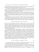
FIGURE 6-4 A typical cervical vertebra (C4 - fourth cervical vertebra). SAF, superior
articular facet; SAP, superior articular process; VB, vertebral body; IAF, inferior articular
facet; IAP, inferior articular process.
279
FIGURE 6-5 Atlas (superior, anterior, and lateral view). Note the kidney-shaped SAFs.
SAF, superior articular facet; IAF, inferior articular facet.
FIGURE 6-6 Axis (superior, anterior, and lateral view). SAF, superior articular facet; VB,
vertebral body; IAF, inferior articular facet; AAF, anterior articular facet; IAP, inferior
articular process; PAF, posterior articular facet.
280
FIGURE 6-7 Cervical spine (anterior view) showing the relationship of the cervical spinal
nerves and the vertebral artery to the transverse processes of the vertebra. Note the transverse
processes of the C7 vertebra lack an anterior tubercle and the relationship of the vertebral
artery to the C7 spinal nerve and the transverse processes.
FIGURE 6-8 Cross-sectional cadaver anatomic section through the C2 vertebral body
showing the bifid spinous process of C2. This is an anatomical landmark used to identify the
C2 vertebra as it is the first cervical vertebra with a bifid spinous process. The spinous
process may be tilted to the right or left. Gentle left and right angulation of the probe in the
longitudinal sagittal plane may be required to visualize these spinous processes.
281
FIGURE 6-9 Paramedian sagittal cadaver anatomic section through the cervical spine
demonstrating the lamina of the cervical vertebrae. VB, vertebral body.
FIGURE 6-10 Cross-sectional cadaver anatomic section through the cervical spine
demonstrating the facet joints. Note that the facet joints are orientated at about 45 degrees to
the horizontal plane in transverse section.
The cervical spinal canal measures about 14 to 20 mm in the mediolateral dimension and
15 to 20 mm in the anteroposterior dimension. The spinal nerves (formed by the anterior and
posterior nerve roots) exit through the neural foramina. These foramina are largest at C2 to
C3 and progressively decrease in size to the C6 to C7 levels. The spinal nerve and ganglion
take up about 33% of the foraminal space. The foramen is bordered anteromedially by the
uncovertebral joints and posterolaterally by the facet joints. The pedicles border the exit
foramina superior and inferiorly. The spinal nerves exit above their corresponding vertebral
bodies. The C1 nerve exits above the C1 vertebra (atlas). The next spinal nerve is C2, exiting
above the C2 vertebra (axis). Following this naming convention, the last cervical nerve root is
C8, and it exits between the C7 and T1 vertebrae (Figs. 6-11 and 6-12).
282
FIGURE 6-11 Cross-sectional cadaver anatomic section through the cervical spine
demonstrating the exiting C5 nerve root. The C5 nerve root exits the neural foramen and is in
close relation to the vertebral artery posteriorly. Both these structures are bound by the larger
anterior tubercle and the smaller posterior tubercle. TP, transverse process.
FIGURE 6-12 Sagittal cadaver anatomic section of the exit neural foramina demonstrating
the C5 nerve root exiting between the transverse processes (TP) of C4 superiorly (C4 TP) and
C5 (C5 TP) inferiorly. The bulk of sternocleidomastoid muscle lies anteriorly and may be
traversed during procedures in the cervical spine.
The anterior spinal artery is located in the central sulcus of the cord, with paired posterior
arteries running on the posterolateral aspect of the cord dorsally. The anterior spinal artery is
an important artery: it supplies the anterior two-thirds of the cervical spinal cord. The artery
283
receives blood supply from the paired anterior spinal branches that arise from the
cervicomedullary junction portion of the vertebral arteries. This anatomy is relevant for
epidural steroid injections. The radicular arteries also supply the nerve roots and spinal cord.
These radicular arteries arise from the aorta. In the lower cervical spine, they arise from the
vertebral arteries and run in an anteromedial direction with respect to the neural foramina. In
the lower cervical spine, large radiculomedullary branches contribute blood supply to the
anterior spinal artery as well. Branches of the ascending and deep cervical arteries
anastomose with the vertebral artery branches and contribute to the anterior spinal artery. The
ascending cervical artery arises from the thyrocervical trunk or subclavian artery.
The posterior subclavian artery also gives off the deep cervical artery and the superior
intercostal artery. The deep cervical artery gives spinal branches from levels C7 to T1, known
as the cervical radiculomedullary arteries. As mentioned earlier, these arteries can contribute
supply to the anterior spinal artery. These radiculomedullary arteries are found along the
length of the intervertebral foramina and can be compromised during injection, potentially
leading to damage to the anterior spinal artery. The posterior third of the cervical spinal cord
is supplied by small paired posterior spinal branches.
Atlas (C1)
The atlas is the first cervical vertebra (Fig. 6-5) and forms the joint that connects the spine to
the skull (Fig. 6-13). It is ring shaped and lacks both a vertebral body and spinous process
(Fig. 6-5). It also lacks a true facet joint and has two arches: anterior and posterior. The
posterior arch is usually quite small. A thick anterior arch, lateral masses, and transverse
processes on either side make up the rest of the atlas ring. It also has a rudimentary posterior
tubercle. On each lateral mass is a facet (zygapophyseal) joint. The superior articular facets
are kidney shaped (Fig. 6-5), concave, and face upwards and inwards (imagine your hands
cupping water from a running tap). The inferior articular facets are flat and face downwards
and outwards. The transverse processes project laterally from each lateral mass and are longer
than all the others (Figs. 6-2 and 6-3).
FIGURE 6-13 Median sagittal cadaveric anatomic section through the cervical spine
demonstrating C1 in relation to the occiput and the rest of the cervical vertebrae. Note how
284
closely the dura and the cervical spinal cord are to the spinous processes. The vertebral
bodies (VB) are labeled as anterior complex to demonstrate that sonographically, the
individual components (including the posterior longitudinal ligament complex) are difficult to
distinguish individually. SP, spinous process.
Axis (C2)
The second cervical vertebra (Fig. 6-6) is recognized by the presence of the dens (odontoid
process), which is a strong toothlike process that projects upwards from the body (Fig. 6-6).
The dens is believed to represent the body (centrum) of the atlas, which has fused with the
body of the axis. The odontoid process articulates with the atlas to form the rotatory
atlantoaxial joint. The joint is strengthened by periarticular ligaments (the apical, alar, and
transverse ligaments). The axis is made up of a vertebral body, pedicles, lamina, and
transverse and spinous processes. The atlas articulates with the axis (Fig. 6-2) at the superior
articular facets of C2. In order to meet the inferior articular processes of C1, the C2 superior
articular facets face upwards and outwards. There is an extensive and densely packed
network of blood vessels around the dens. These are supplied by the paired anterior and
posterior ascending arteries (which arise from the vertebral arteries at the C3 level, carotid
wall vessels, and the ascending pharyngeal arteries).
The transverse ligament secures the odontoid process to the posterior atlas and acts to
prevent subluxation of C1 on C2. Accessory ligaments arise posterior to the transverse
ligament and insert on the lateral aspects of the atlantoaxial joint. The apical ligament, part of
the accessory ligaments mentioned earlier, connect the anterior lip of the foramen magnum to
the tip of the dens. Paired alar ligaments also attach the tip of the dens to the anterior foramen
magnum. The tectorial membrane is a cranial continuation of the posterior longitudinal
ligament, attaching to the anterior lip of the foramen magnum. A broad accessory atlantoaxial
ligament connects C1 and C2 and connects to the occiput. They contribute to craniocervical
stability. The lack of bony borders at the atlantoaxial joint results in wider acoustic windows
at this level, but this is countered by the tortuous course of the ascending vertebral arteries.
Seventh Cervical Vertebra (C7)
This is also known as the “vertebral prominence” because it has a long and prominent
spinous process (Fig. 6-1) that is palpable from the skin surface. The spinous process is also
thick, nearly horizontal, and is not bifid but ends in a tubercle. The transverse process of C7
is relatively large and lacks an anterior tubercle (Fig. 6-7). The foramen transversarium on the
transverse processes of C7 are small but may be duplicated or even absent.
Computed Tomography Anatomy of the Cervical Spine
Figs. 6-14 to Fig. 6-21
285
FIGURE 6-14 Transverse CT section through the cervical spine demonstrating the facet
joints at the C5 to C6 level. The inferior articular pillar of the C6 (vertebra inferior to the
joint) is located anterior to the joint space. The superior articular pillar of the C5 (vertebra
superior to the joint) is located posterior to the joint space.
FIGURE 6-15 Transverse CT section through the cervical spine demonstrating the facet
joints at the C6 to C7 level. Note the relatively horizontal orientation of the facet joint as
opposed to the obliquity of the C5 to C6 facet superiorly.
286
FIGURE 6-16 Transverse CT section through the cervical spine. The lamina on the
posterolateral aspect of the vertebra flows into the transverse process. The longus colli
muscle lies on the anteromedial aspect of the transverse process.
FIGURE 6-17 Transverse CT section through the body of the seventh cervical spine
demonstrating its large and prominent spinous process (vertebra prominence). VB, vertebral
body.
287
FIGURE 6-18 Sagittal CT section of the cervical spine demonstrating the posterior arch of
C1 and the corresponding laminae of the vertebrae inferiorly.
FIGURE 6-19 Sagittal CT section of the cervical spine more laterally in the cervical spine
demonstrating the overlapping articular pillars that form the facet joints. In the same cut,
transverse processes may also be visualized on CT. The transverse processes may be
obscured on ultrasound by the bony reflections of the facet joints.
288
FIGURE 6-20 Sagittal CT section of the cervical spine in the midline demonstrating the
spinous processes aligned with the occiput. The tips of the spinous processes are echogenic
on ultrasound. Starting with the broad echogenic base of the occiput, these echogenic points
can be used to identify the levels of the cervical spine. Note that the spinous process of C1 is
hypoplastic relative to C2 and recessed. It is important to identify this recess to avoid
mislabeling C2 as the first cervical vertebra on ultrasound.
FIGURE 6-21 Sagittal CT section of the cervical spine demonstrating the relationships of
the articular pillars, facet joints, and the vertebral artery within the foramen transversarium.
Also note the oblique angulation of the facet joints in the sagittal plane. In order for
successful facet joint injection, the needle should be parallel to the angulation of the joint.
289
Magnetic Resonance Anatomy of the Cervical Spine
Figs. 6-22 to 6-38
FIGURE 6-22 Sagittal T2-weighted MRI section of the cervical spine demonstrating the
posterior arch of C1 and the corresponding laminae of the vertebrae inferiorly. Note the slight
overlap of the laminae, which is seen on ultrasound as a “horse head” configuration.
Cerebrospinal fluid (hyperintense signal) bathes the small nerve roots in the spinal canal.
FIGURE 6-23 Sagittal T2-weighted MRI section of the cervical spine more laterally in the
cervical spine demonstrating the overlapping articular pillars that form facet joints.
290
FIGURE 6-24 Sagittal MRI section of the cervical spine demonstrating the vertebral artery
within the foramen transversarium. The exiting nerve roots are well demonstrated as ovoid
hypointense foci as they are seen en face. The nerve roots are closely related to the vertebral
artery.
FIGURE 6-25 Sagittal MRI section of the cervical spine in the midline demonstrating the
spinous processes aligned with the occiput. The tips of the spinous processes are echogenic
on ultrasound. Starting with the broad echogenic base of the occiput, these echogenic points
can be used to identify the levels of the cervical spine. Note that the spinous process of C1 is
hypoplastic relative to C2 and recessed. It is important to identify this recess to avoid
mislabeling C2 as the first cervical vertebra on ultrasound. MRI demonstrates the relationship
of the cervical spine relative to the dura, with surrounding cerebrospinal fluid.
291
FIGURE 6-26 Sagittal MRI section of the cervical spine demonstrating the broad base of
the occiput. Note that the spinous process of C1 is hypoplastic relative to C2 and recessed. It
is important to identify this recess to avoid mislabeling C2 as the first cervical vertebra on
ultrasound.
FIGURE 6-27
Sagittal oblique MRI section of the cervical spine demonstrating the
292
epidural space and the dura posteriorly. The epidural space in the cervical spine is a potential
space (unlike the lumbar spine, where fat fills the epidural space).
FIGURE 6-28 Transverse MRI section through the cervical spine demonstrating the
laminae of C2. The cervical spinal cord is well visualized centrally, with nerve roots exiting
on either side of the cord, extending beyond through the exit foramina.
FIGURE 6-29 Transverse MRI section through the cervical spine demonstrating the facet
joints. The facets are angled posteriorly at this level and gradually assume a more horizontal
orientation in the lower cervical spine. The vertebral body and anterior and posterior
longitudinal ligaments are collectively referred to as the anterior complex in sonography as
they are not separately distinguishable.
293
FIGURE 6-30 Paramedian sagittal MRI of the cervical spine demonstrating the almost
vertical oblique course of the cervical nerve roots of C4 and C5 as they plunge toward the
interscalene groove. The large overlying sternocleidomastoid muscle is demonstrated.
FIGURE 6-31 Paramedian sagittal MRI section of the cervical spine demonstrates the C5
nerve root beyond the exit foramen. It runs between the transverse processes of C4 and C5 en
route to the interscalene groove (between the anterior and middle scalene muscles).
294
FIGURE 6-32 Transverse MRI section through the cervical spine demonstrating the
exiting C5 nerve root. The C5 nerve root exits the neural foramen and is in close relation to
the vertebral artery posteriorly. Both these structures are bound by the larger anterior tubercle
and the smaller posterior tubercle.
FIGURE 6-33 Transverse MRI section through the cervical spine demonstrating the facet
joints at the C5 to C6 level. The inferior articular pillar of the C6 (vertebra inferior to the
joint) is located anterior to the joint space. The superior articular pillar of the C5 (vertebra
superior to the joint) is located posterior to the joint space. Note that at C5 to C6, the facets
remain oblique relative to the horizontal plane. They take a more horizontal course from the
C6 to-C7 and C7 to T1 levels.
295
FIGURE 6-34 Transverse MRI section through the cervical spine demonstrating the
prominent anterior tubercle of C6 (Chassaignac’s tubercle). This is a sonoanatomical
landmark to identify C6 and the exiting C6 nerve root immediately posterior to the tubercle.
The longus colli muscle lies anteromedial to the Chassaignac tubercle in close relationship
with the carotid artery on its lateral aspect.
FIGURE 6-35 Transverse MRI section through the cervical spine demonstrating the C6 to
C7 facet joints. In comparison with the C5 to C6 level, the facets are orientated in a more
horizontal plane.
296
FIGURE 6-36 Transverse MRI section through the cervical spine at the C6 to C7 foramen
demonstrating the exiting C7 nerve root running immediately posterior to the vertebral artery.
The nerve root is en route between the anterior and middle scalene to form the brachial
plexus. Note the presence of the internal jugular vein (IJV), carotid artery, and the vertebral
artery.
FIGURE 6-37 Transverse MRI section through the cervical spine demonstrating the C7
transverse processes. The anterior complex (vertebral body) is flanked by the vertebral
arteries on both sides.
297
FIGURE 6-38 Transverse MRI section through the cervical spine demonstrating the
longus colli muscles running anterior to the transverse processes. Note that the vertebral
arteries lie immediately posterior to the longus colli at the C7 level. The carotid artery is
located on the anterolateral aspect of the muscle, and the thyroid gland forms the anterior
border of the muscle. With ultrasound, a safe trajectory between the artery and thyroid gland
toward the longus colli can be planned. The sternocleidomastoid muscle overlies the
anterolateral aspect of the neck and may be traversed during a stellate ganglion block.
Ultrasound for Cervical Facet Joint Injection
Ultrasound Scan Technique
1a. Patient position:
a.Lateral approach: The patient is placed in the lateral decubitus position. The head is
placed on a pillow so that the shoulders are square to the examination couch. Hair
should be tied and lifted clear from the side of the neck to prevent contamination
during the procedure (Fig. 6-39).
298
FIGURE 6-39 Position of the patient and ultrasound transducer during a paramedian
sagittal scan of the cervical facet joints. The transducer is placed about 1 to 2 cm away from
the midline and angulated medially toward the facet joints. A similar position is used for
performing third occipital nerve blocks (refer to text).
b.Posterior approach: The posterior approach has the distinct advantage of allowing the
patient to be placed prone and both joints being accessible without having to change
position. It can be uncomfortable to the patient if multiple levels are blocked, so this
position is suited for faster access to both sides of the neck (Fig. 6-40).
FIGURE 6-40 Position of the patient and ultrasound transducer during a paramedian
sagittal scan of the cervical facet joints. The transducer is placed about 1 to 2 cm away from
the midline and angulated medially toward the facet joints. The posterior approach allows
more room to maneuver the needle and probe. It also allows simultaneous access to both
sides of the spine, but is generally more uncomfortable for patients.
299
1b. Position of operator and ultrasound machine:
The operator sits or stands facing the patient’s back in the lateral position or on the side of
the patient for the posterior approach. It is more comfortable for the operator if the
nondominant hand anchors the transducer and the dominant hand manipulates the needle.
2.Transducer selection:
Due to the density of muscular structures around the cervical spine, a curvilinear probe
(5–2 MHz) is used for imaging and blocks in the cervical spine (facet blocks and occipital
nerve blocks). The in-plane resolution of the images is reduced compared with a linear
probe, but this is often necessary due to the depth of the facet joints in relation to the skin.
The probe footprint is often large, and maneuvering the transducer into the correct
position requires practice. Although visualization of small (2 mm and below) structures is
compromised by using a curvilinear probe traditionally, processing techniques such as
spatial compound imaging and tissue harmonic imaging on new ultrasound machines
enable us to examine tissues at those depths with reasonable clarity. Beam steering
technology (which is an offshoot of compound imaging) enhances needle visualization,
and color B-mode imaging (such as indigo or sepia hue) aids the human eye for image
visualization when image contrast is poor.
3.Scanning technique for facet joint blocks:
A sagittal plane scan is performed in the midline, using the spinous processes to identify
the level to inject. Align the transducer in a craniocaudal direction with respect to the
cervical spine, starting at the occiput and sliding inferiorly. C1 has a very small or absent
spinous process (Figs. 6-41 and 6-42), and the first bifid spinous process will be C2. The
transducer can be slid inferiorly until the desired level for the injection is reached. Having
identified the level, the transducer should be shifted slightly laterally along the lamina by
about 1 to 2 cm from the midline. From there, a slight lateral shift of the transducer will
reveal facet joints, which appear with a characteristic “saw sign.” The probe may have to
be angled medially to produce a slightly paramedian sagittal oblique image. The needle is
inserted in a posterior-to-anterior plane and followed in real time (Fig. 6-43).1
FIGURE 6-43 Paramedian sagittal sonogram of the cervical spine lateral to the laminae
demonstrating the overlying echogenic “hills” of the facet joints.
300