mạng máy tính06b ethernet fundamentals sinhvienzone com
Bạn đang xem bản rút gọn của tài liệu. Xem và tải ngay bản đầy đủ của tài liệu tại đây (3.68 MB, 57 trang )
Networking Basics
ETHERNET
FUNDAMENTALS
Version 3.0
Cisco Regional Networking Academy
SinhVienZone.com
/>
Objectives
• Describe the basics of Ethernet technology.
• Explain naming rules of Ethernet technology.
• Define how Ethernet and the OSI model interact.
• Describe the Ethernet framing process and frame
structure.
• List Ethernet frame field names and purposes.
• Identify the characteristics of CSMA/CD.
• Describe the key aspects of Ethernet timing, interframe
spacing and backoff time after a collision.
• Define Ethernet errors and collisions.
• Explain the concept of auto-negotiation in relation to
speed and duplex.
SinhVienZone.com
/>
Table of Content
1
2
Ethernet Fundamentals
Ethernet Operarion
SinhVienZone.com
/>
ETHERNET FUNDAMENTALS
SinhVienZone.com
/>
Introduction to Ethernet
• In 1970’s
– CSMA/CD developed at the University of Hawaii
• In 1980’s
– First experimental Ethernet system at Xerox PARC
• In 1985, IEEE 802.3 released
• Digital Equipment, Intel, and Xerox jointly develop
& release Ethernet Version 2.0
• Substantially compatible with IEEE 802.3
• In 1995, IEEE announced a standard for a 100Mbps Ethernet. This was followed by standards for
Gigabit ethernet in 1998 and 1999.
SinhVienZone.com
/>
The success of Ethernet is due to the following factors
• Simplicity and ease of maintenance
• Ability to incorporate new technologies
• Reliability
• Low cost of installation and upgrade
SinhVienZone.com
/>
IEEE Ethernet naming rules
• 10Base-2:
50Ω Thin cable, 185m.
• 10Base-5:
50Ω Thick cable, 500m.
• 10Base-T:
100Ω UTP cable, 100m.
• 10Base-F:
Fiber optic cable, 1000m.
• 100Base-TX: 100Ω UTP/STP cable, 100m.
• 100Base-T4: 100Ω UTP (4p) cable, 100m.
• 100Base-FX: Fiber optic cable, 400m.
• 1000Base-T: 100Ω UTP/STP cable, 100m.
SinhVienZone.com
/>
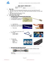
Ethernet and the OSI model
SinhVienZone.com
/>
A Repeater
• Standards guarantee minimum bandwidth and
operability by specifying the maximum number of
stations per segment, maximum segment length,
maximum number of repeaters between stations,
etc.
• Stations separated by repeaters are within the same
collision domain. Stations separated by bridges or
routers are in different collision domains.
SinhVienZone.com
/>
Layer 1 vs Layer 2
• Layer 1 cannot organize streams of bits.
• Layer 2 uses framing to organize or group the bits.
• Layer 1 cannot name or identify computers.
• Layer 2 uses an addressing process to identify computers.
• Layer 1 cannot communicate with the upper-level layers.
• Layer 2 uses Logical Link Control (LLC) to communicate
with the upper-level layers.
• Layer 1 cannot decide which computer will transmit binary
data.
• Layer 2 uses Media Access Control (MAC) to decide which
computer will transmit.
SinhVienZone.com
/>
Ethernet and the OSI mode
SinhVienZone.com
/>
Naming
• Every computer has a unique way of identifying
itself : MAC address or physical address.
• The physical address is located on the Network
Interface Card (NIC).
• MAC addresses have no structure, and are
considered flat address spaces. MAC addresses are
sometimes referred to as burned-in addresses
(BIAs) because they are burned into read-only
memory (ROM) and are copied into random-access
memory (RAM) when the NIC initializes.
• 0000.0c12.3456 or 00-00-0c-12-34-56.
SinhVienZone.com
/>
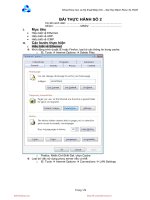
MAC address format
The first six hexadecimal
The remaining six
digits, which are administered
hexadecimal digits comprise
by the IEEE, identify the
the interface serial number.
manufacturer or vendor.
SinhVienZone.com
/>
Using MAC addresses
Data A D Data A D Data A D Data A D
Destination Address
Source Address
SinhVienZone.com
/>
Layer 2 framing : Why framing is necessary?
• Which computers are communicating with one
another.
• When communication between individual
computers begins and when it terminates.
• A record of errors that occurred during the
communication.
• Whose turn it is to ―talk‖ in a computer
―conversation‖.
SinhVienZone.com
/>
Frame format diagram
SinhVienZone.com
/>
Frame format diagram
• The frame format diagram shows different
groupings of bits (fields) that perform other
functions.
• Read them from left to right.
SinhVienZone.com
/>
Generic frame format
• There are many different types of frames
described by various standards.
SinhVienZone.com
/>
Start frame field
• The Start Frame field tells other devices
on the network that a frame is coming
down the wire.
SinhVienZone.com
/>
Address field
• The Address field stores the source and
destination MAC addresses.
SinhVienZone.com
/>
Length/Type field
•
•
•
•
The Type/Length field is an optional field
Exact length of frame, or
Layer 3 protocol making the sending request, or
Not used
SinhVienZone.com
/>
Data field
• The Data field is the actual information
being sent by the upper layer protocols.
Therefore, it will be all upper layer data.
SinhVienZone.com
/>
FCS field
•
•
•
Cyclic Redundancy Check (CRC) - performs polynomial
calculations on the data
Two-dimensional parity - adds an 8th bit that makes an 8 bit
sequence have an odd or even number of binary 1's
Internet checksum - adds the values of all of the data bits to
arrive at a sum
SinhVienZone.com
/>
Stop frame field
• The Stop Frame field, also called the
Frame Trailer, is an optional field that is
used when the length of the frame was
not specified in the Type/Length field.
SinhVienZone.com
/>
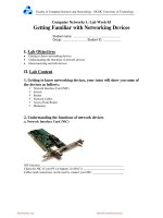
Ethernet frame structure
Ethernet-II( DIX 2.0)
7+1
6
6
2
46-1500
4
Preamble
Dest.
Address
Source
Address
Type
Data
FCS
IEEE 802.3
1
6
6
Preambl
e
Start
Frame
Delimiter
Dest.
Address
Source
Address
SinhVienZone.com
2
64-1500
4
Length
7
802.2
Header &
Data
FCS
/>