Improving Performance of the Asynchronous Cooperative Relay Network with Maximum Ratio Combining and Transmit Antenna Selection Technique
Bạn đang xem bản rút gọn của tài liệu. Xem và tải ngay bản đầy đủ của tài liệu tại đây (510.44 KB, 9 trang )
VNU Journal of Science: Comp. Science & Com. Eng., Vol. 33, No. 1 (2017) 28-36
Improving Performance of the Asynchronous Cooperative
Relay Network with Maximum Ratio Combining
and Transmit Antenna Selection Technique
The Nghiep Tran∗, Van Bien Pham, Huu Minh Nguyen
Faculty of Radio-Electronics, Le Quy Don Technical University,
236 Hoang Quoc Viet Street, Cau Giay, Hanoi, Vietnam
Abstract
In this paper, a new amplify and forward (AF) asynchronous cooperative relay network using maximum
ratio combining (MRC) and transmit antenna selection (TAS) technique is considered. In order to obtain a
maximal received diversity gain, the received signal vectors from all antennas of the each relay node are jointly
combined by MRC technique in the first phase. Then, one antenna of each relay node is selected for forwarding
MRC signal vectors to the destination node in the second phase. The proposed scheme not only offers to reduce
the interference components induced by inter-symbol interference (ISI) among the relay nodes, but also can
effectively remove them with employment near-optimum detection (NOD) at the destination node as compared
to the previous distributed close loop extended-orthogonal space time block code (DCL EO-STBC) scheme. The
analysis and simulation results confirm that the new scheme outperforms the previous cooperative relay
networks in both synchronous and asynchronous conditions. Moreover, the proposed scheme allows to reduce
the requirement of the Radio-Frequency (RF) chains at the relay nodes and is extended to general multi-antenna
relay network without decreasing transmission rate.
Received 17 October 2016; Revised 22 March 2017; Accepted 24 April 2017
Keywords: Maximum ratio combining, transmit antenna selection, near-optimum detection, distributed
space-time coding, distributed close-loop extended orthogonal space time block code.
1. Introduction*
node, and (2) decode and forward (DF) [7-12],
that decodes the received signal from the
source, re-encode the decoded data, and
transmit to the destination node. This paper
focuses on simple relaying protocols based on
amplify and forward strategy since it is easier to
implement them in the small relay nodes and
moreover, it does not require the knowledge of
the channel fading gains at the relay nodes.
Therefore, we can avoid imposing bottlenecks
on the rate by requiring some relays to decode.
The distributed close loop extended
orthogonal space time block code (DCL
EO-STBC) [1] and distributed close loop
quasi-orthogonal space time block code (DCL
Space-time block coding (STBC) can be
employed in the distributed manner, referred as
a distributed STBC (DSTC), to exploit the
spatial diversity available more efficiently and
provide coding gain in these networks.
Generally, there are two types of relaying
methods that were discussed in the literatures:
(1) amplify and forward (AF) [1-6], that is
linear process, in which the received signals are
amplified then transmitted to the destination
_______
*
Corresponding author. E-mail.:
/>
28
T.N. Tran et al. / VNU Journal of Science: Comp. Science & Com. Eng., Vol. 33, No. 1 (2017) 28-36
QO-STBC) [2] are proposed for two
dual-antenna relay nodes in the AF strategy. It
has been shown that both the DCL EO-STBC and
29
DCL QO-STBC achieve cooperative diversity
order of four with unity data transmission rate
between the relay nodes and the destination node.
G
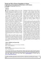
Figure 1. Example number of ISI components for DCL EO-STBC [1] and DCL QO-STBC [2].
However, the existing research on DSTC
schemes [1-3], and [8], where each relay
antenna processes its received signal
independently, so that this received signal
combining is not optimal for multi-antenna
relay networks because the co-located antennas
of the each relay are treated as distributed
antennas.
Additionally, due to the distributed nature
of cooperative relay nodes, the received DSTC
symbols at the destination node will damage the
orthogonal feature by introducing inter-symbol
interference (ISI) components and degrade
significantly the system performance. In the
asynchronous cooperative relay networks, the
number of ISI components depends on both the
structure of the DSTC and the number of the
imperfect synchronous links [11]. The Fig. 1
illustrates a representation of ISI components at
the received symbols for the DCL EO-STBC [1]
and DCL QO-STBC [2]. It could be evident that
the DCL EO-STBC scheme has less number of
ISI
components
than
the
DCL
QO-STBC one. Note that, they have the similar
configuration network and the imperfect
synchronous channel assumptions. Moreover, the
destination node uses the detection of interference
cancellation, called near-optimum detection
(NOD) [1, 9] and parallel interference
cancellation detection [2], to eliminate ISI
components, which is only solution at
the receiver.
As mentioned earlier, although a lot of
phase feedback schemes can be proved to
improve the distributed close loop system
performance, other problems of these systems
have to use all antennas of the relay node for
forwarding the signals to the destination node.
This improvement comes along with an
increase in complexity, size, and cost in
hardware design [5]. Moreover, the previous
DSTC schemes can not be directly applied on
the multi-antenna relay networks, where each
relay has more than two antennas.
30
T.N. Tran et al. / VNU Journal of Science: Comp. Science & Com. Eng., Vol. 33, No. 1 (2017) 28-36
In this paper, we propose the asynchronous
cooperative relay network using optimal MRC
technique for jointly combining received
signals from the source node. In the second
phase, the TAS technique utilizes at the relay
nodes which chooses the best antenna to
retransmit the resulting signals to the
destination. Different with all of the abovementioned papers, our proposed scheme uses
TAS technique to reduce the number of the ISI
components and the requirement of the RF
chains. Moreover, the destination node utilizes
the NOD to remove the ISI components
effectively.
The rest of the paper is organized as
follows: In the Sec. 2, we describe a new
asynchronous cooperative relay network with
the MRC and TAS technique (MRC/TAS) at
the relay nodes; the Sec. 3 represents the
application of the near-optimum detection
(NOD) at the destination node for the proposed
scheme; simulation results and performance
comparisons are represented in Sec. 4; finally,
the conclusion follows in Sec. 5.
Notations: the bold lowercase 𝑎 and bold
uppercase 𝐴 denote vector and matrix,
respectively; [. ]𝑇 , [. ]∗ , [. ]𝐻 and ‖. ‖2 denote
transpose, conjugate, Hermitian (complex
conjugate) and Frobenius, respectively; 𝐴
indicates the signal constellation.
2.fTheproposedasynchronouscooperativerela
ynetworkwith MRC/TAS technique
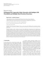
Figure 2. The proposed cooperative relay network
with MRC/TAS technique.
In this paper, a new asynchronous
cooperative relay network with MRC and TAS
technique is considered as shown in Fig. 2. This
model consists of a source node, a destination
node and two relay nodes. Each terminal node,
i.e. the source node and the destination node, is
equipped with a single antenna while each relay
node is equipped with 𝑁𝑅 antennas. It is
assumed that there is no Direct Transmission
(DT) connection between the source and the
destination due to shadowing or too large
distance. The relay node operating is assumed
in half-duplex mode and AF strategy. The
channel coefficient from the source node to 𝑖𝑡ℎ
the antenna of the 𝑘𝑡ℎ relay node and the
channel coefficient from the 𝑖𝑡ℎ antenna of the
𝑘𝑡ℎ relay node to the destination node indicate
𝑓𝑖𝑘 and 𝑔𝑖𝑘 (for 𝑘 = 1,2; 𝑖 = 1, . . . , 𝑁𝑅 ),
respectively. The noise terms of the relay and
destination node are assumed AWGN with
distribution 𝐶𝑁(0,1). The total transmission
power of one symbol is fixed as 𝑃 (dB). Thus,
the optimal power allocation is adopted as
follows [12]
𝑃
𝑃
𝑃1 = , 𝑃2 = ,
(1)
2
4
where 𝑃1 and 𝑃2 are the average
transmission power at the source and each relay
node, respectively.
2.1. In the first phase (broadcast phase)
The information symbols are transmitted
from the source node to the destination node via
two different phases. In the first phase, the
source node broadcasts the sequence of
quadrature phase-shift keying (QPSK), which is
grouped
into
symbol
vector
𝐬(𝑛) =
[𝐬(1, 𝑛) −𝐬 ∗ (2, 𝑛)]𝑇
The received symbol vector at 𝑖𝑡ℎ antenna
of the 𝑘𝑡ℎ relay node is given by
𝐫𝑖𝑘 (𝑛) = √𝑃1 𝑓𝑖𝑘 𝐬(𝑛) + 𝐯𝑖𝑘 (𝑛),
for 𝑘 = 1, 2; 𝑖 = 1, . . . , 𝑁𝑅 (2)
where 𝐯𝑖𝑘 (𝑛) is the additive Gaussian noise
vector at each antenna of each relay node.
In the conventional DSTC scheme [1, 2], the
transmitted symbols from each relay antenna at
the same relay node is designed to be a linear
function of the received signal and its conjugate.
T.N. Tran et al. / VNU Journal of Science: Comp. Science & Com. Eng., Vol. 33, No. 1 (2017) 28-36
This paper uses distributed matrices 𝐀𝑘 , 𝐁𝑘
with Alamouti DSTC [13] to obtain a unity
transmission rate and linear complexity
detection. Note that, the factor √𝑃2 /(𝑃1 + 1) in
the equation (4) ensures that the average
transmission power at each relay node is 𝑃2 .
It is clear that this is not optimal for networks
whose relays have multiple antennas because the
co-located antennas of the same relay are treated
as distributed antennas. In order to achieve the
optimal received diversity gain, the received
symbols at the each relay node are combined by
using MRC technique as follow
𝐫𝑘 (𝑛)
∗
𝑓1𝑘
1
[𝑟1𝑘 (𝑛) ⋯ 𝑟𝑁𝑅 𝑘 (𝑛)] [⋮
=
],
‖𝑓𝑘 ‖𝐹
𝑓𝑁∗𝑅 𝑘
for 𝑘 = 1, 2; 𝑖 = 1, . . . , 𝑁𝑅 ,
(3)
where 𝐫𝑘 (𝑛) is received symbol vector at 𝑘𝑡ℎ
relay node after using MRC process and ‖𝑓𝑘 ‖𝐹 =
2.2. In the second phase (cooperative phase)
In the second phase, the transmit antenna of
each relay node can be selected by below
criterion [14], which achieves a maximal
transmitted diversity gain
𝑢(𝑘) = max |𝑔𝑖𝑘 |2 ; for 𝑘 = 1, 2; 𝑖 =
𝑖=1,...,𝑁𝑅
1, . . . , 𝑁𝑅 ,
(5)
where 𝑢(𝑘) is the selected transmit antenna
index of the 𝑘𝑡ℎ relay node. 𝑔𝑘 (𝑘 = 1, 2)
denotes the channel gain from the selected
transmit antenna of the 𝑘𝑡ℎ relay node to the
destination node. The TAS technique allows to
achieve the transmitted diversity gain in the
second phase.
2
√|𝑓1𝑘 |2 + ⋯ + |𝑓𝑁𝑅 𝑘 | . The transmitted symbol
vector from selected transmit antenna 𝐭 𝑘 (𝑛) is
described by a linear function of 𝐫𝑘 (𝑛) and its
conjugate 𝐫𝑘∗ (𝑛) as follow
𝑃2
(𝐀𝑘 𝐫𝑘 (𝑛) +
𝑃1 +1
𝐭 𝑘 (𝑛) = √
31
𝐁𝑘 𝐫𝑘∗ (𝑛)).(4)
G
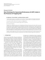
Figure 3. Representation of ISI components between the selected transmit relay antenna
and the destination antenna.
As the previous mention in [1, 2], the
transmitted signals from the cooperative relay
nodes to the destination will undergo different
time delays due to different locations of the
relay nodes. Therefore, the received symbols at
the destination node may not align. Without
loss of generality, we assume that both antennas
of the first relay node (denotes 𝑅1 ) and the
destination node are synchronized perfectly,
whereas both antennas of the second relay node
(denotes 𝑅2 ) and the destination node are
synchronized imperfectly (𝑒. 𝑖. 𝜏2 = 𝜏12 =
𝜏22 ≠ 0) as shown in Fig.3. The received
symbols at the destination are written as follow
𝐲(1, 𝑛) = 𝐭1 (1, 𝑛)𝑔1 (𝑛) + 𝐭 2 (1, 𝑛)𝑔2 (𝑛)
+𝐭 2 (2, 𝑛 − 1)𝑔2 (𝑛 − 1) + 𝐳(1, 𝑛), (6)
32
T.N. Tran et al. / VNU Journal of Science: Comp. Science & Com. Eng., Vol. 33, No. 1 (2017) 28-36
𝐲(2, 𝑛) = 𝐭1 (2, 𝑛)𝑔1 (𝑛) + 𝐭 2 (2, 𝑛)𝑔2 (𝑛) +
𝐭 2 (1, 𝑛)𝑔2 (𝑛 − 1) + 𝐳(2, 𝑛), (7)
where 𝐳(𝑛) is the additive Gaussian noise
vector at the destination. By substituting (4)
into (6) and (7), then taking the conjugate of
𝐲(2, 𝑛), the received symbols at the destination
can be rewritten as
𝐲(1, 𝑛) =
𝑃2 𝑃1
√1+𝑃 (‖𝑓1 ‖𝐹 𝑔1 (𝑛)𝐬(1, 𝑛) +
1
‖𝑓2 ‖𝐹 𝑔2 (𝑛)𝐬(2, 𝑛))
𝑃2 𝑃1
‖𝑓 ‖ 𝑔 (𝑛 − 1)𝐬 ∗ (1, 𝑛 − 1)
+√
1 + 𝑃1 2 𝐹 2
𝑃2
(𝑔 (𝑛)𝐯1 (1, 𝑛) − 𝑔2 (𝑛)𝐯2∗ (2, 𝑛))
+√
1 + 𝑃1 1
+𝐳(1, 𝑛),
‖𝑓 ‖ 𝑔 (𝑛 − 1)𝐬 ∗ (1, 𝑛 − 1)
= [ 2 𝐹 2∗
],
‖𝑓1 ‖𝐹 𝑔2 (𝑛 − 1)𝐬 ∗ (2, 𝑛)
and
𝐰(𝑛)
𝑃2 𝑔1 (𝑛)𝐯1 (1, 𝑛) − 𝑔2 (𝑛)𝐯2∗ (2, 𝑛)
=√
[
]
1 + 𝑃1 𝑔1∗ (𝑛)𝐯1∗ (2, 𝑛) + 𝑔2∗ (𝑛)𝐯2 (1, 𝑛)
𝐳(1, 𝑛)
+[ ∗
].
𝐳 (2, 𝑛)
As similar literatures, the effects of ISIs
from the previous symbols in (8) and (9) are
represented by 𝑔2 (𝑛 − 1). The strengths of
𝑔2 (𝑛 − 1) can be expressed as a ratio as [1]:
𝛽 = |𝑔2 (𝑛 − 1)|2 /|𝑔2 (𝑛)|2 .(11)
(8)
𝑃2 𝑃1
(‖𝑓2 ‖𝐹 𝑔2∗ (𝑛)𝐬(1, 𝑛)
𝐲 ∗ (2, 𝑛) = √
1 + 𝑃1
− ‖𝑓1 ‖𝐹 𝑔1∗ (𝑛)𝐬(2, 𝑛))
𝑃2 𝑃1 ∗
+√
𝑔 (𝑛 − 1)𝐬 ∗ (2, 𝑛)
1 + 𝑃1 2
𝑃2
(𝑔∗ (𝑛)𝐯1∗ (2, 𝑛) + 𝑔2∗ (𝑛)𝐯2 (1, 𝑛))
+√
1 + 𝑃1 1
+𝐳 ∗ (2, 𝑛), (9)
The equation (8) and (9) can be rewritten in
vector form as
𝐲′(𝑛) = [
𝐈i𝑛𝑡 (1, 𝑛)
𝐈i𝑛𝑡 (𝑛) = [
]
𝐈i𝑛𝑡 (2, 𝑛)
𝐲(1, 𝑛)
]
𝐲 ∗ (2, 𝑛)
𝑃2 𝑃1
𝑃2 𝑃1
=√
𝐇𝐬′(𝑛) + √
𝐈 (𝑛)
1 + 𝑃1
1 + 𝑃1 i𝑛𝑡
+𝐰(𝑛), (10)
where
‖𝑓 ‖ 𝑔 (𝑛) ‖𝑓2 ‖𝐹 𝑔2 (𝑛)
𝐇 = [ 1 𝐹 1∗
];
‖𝑓2 ‖𝐹 𝑔2 (𝑛) −‖𝑓1 ‖𝐹 𝑔1∗ (𝑛)
𝐬(1, 𝑛)
𝐬′(𝑛) = [
],
𝐬(2, 𝑛)
The second term of (10), i.e. 𝐈𝑖𝑛𝑡 (, 𝑛) called
ISI components, and the Fig. 3 give that the
received symbols at the destination have two
ISI components. The ISI components of
proposed scheme are reduced in compared to
the previous DSTC schemes [1, 2] (See Fig. 1
in Section 1). It is important that the number of
ISI components of the proposed scheme always
equals two and is independent of the number of
the transmitted relay-antennas. Moreover, the
above analyses show that the TAS technique
not only allows to reduce the requirement of RF
chains at the relay nodes, but also increases at
twice the transmit power at each transmitted
antenna as comparison to the previous
cooperative relay networks. However, the
number of feedback bits of the proposed
scheme is quite larger than the DCL EO-STBC
scheme. It is a reasonable price for the
advantages of the proposed scheme.
3.
Near-Optimumdetection
fortheproposedscheme
(NOD)
As remarked above, although the number of
ISI components have been reduced by using
TAS technique, the ISI components have still
existed in the received symbol vector at the
T.N. Tran et al. / VNU Journal of Science: Comp. Science & Com. Eng., Vol. 33, No. 1 (2017) 28-36
destination node. The existing ISI components
can lead to substantial degradation in system
performance. To the end this lack of the
asynchronous cooperative relay network, the
near-optimum detection (NOD) scheme is
employed at the destination node before the
information detection. In fact, the symbol
𝐬(1, 𝑛 − 1) is known through the use of pilot
symbols at the start of the packet. Therefore, the
interference
components
𝐈𝑖𝑛𝑡 (1, 𝑛) =
∗
‖𝑓2 ‖𝐹 𝑔2 (𝑛 − 1)𝐬 (1, 𝑛 − 1) in the equation
(10) caneliminate as follows:
Step 1: Remove the ISI components
𝐲′(1, 𝑛) − 𝐈𝑖𝑛𝑡 (1, 𝑛)
](12)
𝐲′(2, 𝑛)
Step 2: Apply the matched filter by
multiplying the signals removed the ISI
components in (12) by 𝐇 𝐻 . Therefore, the
estimated signals can be represented as
𝐲′′(1, 𝑛)
𝐲′′(𝑛) = [
] = 𝐇 𝐻 𝐲̂(𝑛)
𝐲′′(2, 𝑛)
𝐲̂(𝑛) = [
𝑃1 𝑃2
(Δ𝐬′(𝑛) +
𝑃1 +1
=√
Λ𝐬 ∗ (2, 𝑛)) + 𝐰𝐷 (𝑛),
(13)
where 𝐲′′(1, 𝑛) and 𝐲′′(2, 𝑛) are given by
𝑃1 𝑃2
𝐲′′(2, 𝑛) = √
(𝜆𝐬(2, 𝑛)
𝑃1 + 1
+ Λ(2, 𝑛)𝐬 ∗ (2, 𝑛))
+𝐰𝐷 (2, 𝑛), (14)
𝑃1 𝑃2
𝐲′′(1, 𝑛) = √
(𝜆𝐬(1, 𝑛)
𝑃1 + 1
+ Λ(1, 𝑛)𝐬 ∗ (2, 𝑛))
+𝐰𝐷 (1, 𝑛), (15)
with
𝜆 0
Δ = 𝐇𝐻 𝐇 = [
],
0 𝜆
Step 3: Apply the Least Square (LS) at the
destination to estimate the transmitted signals
from the source node.
As seen the equation (14) 𝐲′′(2, 𝑛) is only
related to 𝐬(2, 𝑛). In addition, it can be proved
that 𝐰𝐷 (2, 𝑛) is a circularly symmetric
Gaussian random variable with zero-mean and
2
covariance 𝜎𝐖
. Assuming the CSI at the
destination node, 𝐬̃(2, 𝑛)can be detected as
follow
𝐬̃(2, 𝑛) = arg min |𝐲′′(2, 𝑛)
𝐬(2,𝑛)∈𝐴
𝑃1 𝑃2
−√
(𝜆𝐬(2, 𝑛)
𝑃1 + 1
+Λ(2, 𝑛)𝐬 ∗ (2, 𝑛))|2 .
(16)
where 𝐬(2, 𝑛) ∈ 𝐴 is possible transmitted
symbol.
Similarly, substituting 𝐬̃(2, 𝑛) back to the
equation (15), 𝐲′′(1, 𝑛) also is only related to
𝐬(1, 𝑛). Therefore, 𝐬̃(1, 𝑛) can be detected by
𝐬̃(1, 𝑛) = arg min |𝐲′′(1, 𝑛)
𝐬(1,𝑛)∈𝐴
𝑃1 𝑃2
−√
(𝜆𝐬(1, 𝑛)
𝑃1 + 1
+Λ(1, 𝑛)𝐬̃ ∗ (2, 𝑛))|2 .
(17)
Due to the presence of the interference
component 𝐈𝑖𝑛𝑡 (𝑛) in (10), which will destroy
the orthogonality of the received signal causing
a degradation in the system performance when
the conventional detector, e.g., the maximum
likelihood without interference cancellation,
uses at the destination node [1]. However, the
received symbol 𝐲′′(2, 𝑛) in the equation (14)
has no ISI component via the using NOD. It is
noticeable from this equation that the
application of the NOD at the destination
effectively
removes
the
interference
components due to the impact of imperfect
synchronous among the relay nodes.
2
𝜆 = ∑ ‖𝑓𝑘 ‖2𝐹 |𝑔𝑘 (𝑛)|2 ,
𝑘=1
0
Λ = 𝐇 [‖𝑓 ‖ ∗
],
∗
1 𝐹 𝑔2 (𝑛 − 1)𝐬 (2, 𝑛)
𝐻
and 𝐰𝐷 (𝑛) = 𝐇 𝐰(𝑛).
𝐻
33
4. Comparisonresults
In this section, we present some numerical
results to demonstrate the performance of our
proposed cooperative relay network with MRC
and TAS technique. In all figures, the bit error
34
T.N. Tran et al. / VNU Journal of Science: Comp. Science & Com. Eng., Vol. 33, No. 1 (2017) 28-36
rates (BER) are shown as a function of the total
transmit power in the whole network. The
transmit information symbols are chosen
independently and uniformly from QPSK
constellation. It is assumed that all channels are
quasi-static Rayleigh fading channels. The
destination node completely acquires the
channel information states from the source to
the relays and from the relays to the destination.
Figure 4. BER performance comparison
of the proposed MRC/TAS and DCL EO-STBC
scheme [1] in the perfect synchronous case.
Firstly, Fig. 4 illustrates the BER
performance of the proposed MRC/TAS DSTC
and DCL EO-STBC scheme [1] in the perfect
synchronous case where each relay node equips
two antennas. As seen the Fig. 4, the proposed
scheme outperforms the previous DCL
EO-STBC scheme. For example, to achieve a
BER = 10−3 we need 𝑃 of ~17 dB for the
proposed MRC/TAS DSTC scheme and ~21
dB for the DCL EO-STBC scheme. Secondly,
the system performance of the MRC/TAS
DSTC is simulated in the perfect synchronous
assumption and using three antennas at each
relay. The left curve of the Fig. 4 shows that the
system performance of proposed scheme is
improved considerably with increasing the
number of antennas of each relay node. The
improvement of the proposed scheme is
because that our scheme achieves both maximal
received diversity gain in the first phase and
cooperative transmit diversity gain in the
second phase. Moreover, the proposed scheme
has less requirement of RF chains of the relay
than the previous works and remains unity
transmission rate between the relay and the
destination.
The impact of imperfect synchronization is
performed by changing the value of 𝛽 = 0, −6
dB, which means adjusting the effect of
different time delays. Fig. 5 shows the BER
performance comparisons of the proposed
MRC/TAS DSTC scheme and the previous
DCL EO-STBC scheme [1] with the utilizing
NOD at the destination node. In this case, the
MRC/TAS DSTC scheme has similar
configuration network as comparison with DCL
EO-STBC scheme [1]. The BER performance
of the proposed scheme outweighs the previous
cooperative relay network. As shown in Fig. 5,
when the BER is 10−3 (at 𝛽 = −6 dB), the
proposed scheme can get an approximate 5 dB
gain over the DCL EO-STBC scheme. It could
be noticeable that the proposed MRC/TAS
DSTC scheme is more robust against the effect
of the asynchronous.
Figure 5. BER performance comparison of the
MRC/TAS DSTC (𝑁𝑅 = 2) and the DCL
EO-STBC [1] with the utilizing NOD scheme.
In order to examine the advantages of
increasing the number of the relay-antennas, the
BER of the proposed scheme is performed with
three antennas at each relay node and various
asynchronous channel conditions. The Fig. 6
demonstrates that the MRC/TAS DSTC scheme
owning three relay-antennas has greater system
performance than, in the similar asynchronous
condition, the DCL EO-STBC one using two
antennas at each relay node. For example, at the
T.N. Tran et al. / VNU Journal of Science: Comp. Science & Com. Eng., Vol. 33, No. 1 (2017) 28-36
BER of 10−3 (at 𝛽 = −6 dB), the proposed
scheme can obtain about 9 dB gain over the
DCL EO-STBC one. The enhancing
performance is achieved as the MRC/TAS
DTSC scheme can get a higher gain including
both received and transmitted diversity.
Figure 6. BER performance comparison of the
MRC/TAS DSTC (𝑁𝑅 = 3) and the DCL
EO-STBC [1] with the utilizing NOD scheme.
5. Conclusions
This paper proposes the AF asynchronous
cooperative relay network using MRC and TAS
technique. The use of MRC technique for
combining multiple received symbols is proved
to obtain maximal received diversity gain in
compared to conventional DSTC scheme [1,2].
In the second phase, the TAS technique allows
to reduce the ISI components among the relay
nodes. The analyses and simulation results
demonstrate that the proposed scheme with the
employment of the NOD works effectively in
various synchronization error levels. In other
words, the MRS/TAS DSTC scheme is more
robust against the effect of the asynchronous.
The proposed scheme has less requirement of
RF chains at the relay and exploits the the
advantage of multi-antennas more effectively in
comparison to the previous one. We believe that
the MRC/TAS DSTC scheme can be useful for
the distributed relay networks using multiantennas at the relay nodes like sensor wireless
network or Ad hoc network under the
asynchronous conditions.
35
References
[1] W. Qaja, A. Elazreg, and J. Chambers,
“Near-Optimum Detection for Use in ClosedLoop Distributed Space Time Coding with
Asynchronous Transmission and Selection of
Two Dual-Antenna Relays," in Proc. Wireless
Conference (EW), Guildford, UK, Apr. 2013,
pp. 1-6.
[2] W. M. Qaja, A. M. Elazreg, and J. A. Chambers,
“Distributed Space Time Transmission with
Two Relay Selection and Parallel Interference
Cancellation
Detection
to
Mitigate
Asynchronism," in Proc. European Symposium
on Computer Modeling and Simulation (EMS),
Valetta, Malta, Nov. 2012, pp. 220-225.
[3] Astal M-T EL, Abu-Hudrouss, Ammar M, and
Olivier Jan C, “Improved signal detection of
wireless relaying networks employing space-time
block codes under imperfect synchronization,”
Wireless Personal Communications, vol.82, no.1,
2015, pp. 533-550.
[4] Alageli, Mahmoud, Aissa Ikhlef, and Jonathon
Chambers, “Relay selection for asynchronous
AF relay networks with frequency selective
channels,” in Proc. Inter. Workshop on Signal
Processing Advances in Wireless Communi.,
Aug. 2016, pp. 1-5.
[5] Gonzalez, Diana Cristina, Daniel Benevides da
Costa, and Jose Candido Silveira Santos Filho,
“Distributed TAS/MRC and TAS/SC Schemes
for Fixed-Gain AF Systems With Multiantenna
Relay: Outage Performance,” IEEE Transac. on
Wireless Communications, vol.15, no.6,
pp.4380-4392, 2016.
[6] Y. Jing and B. Hassibi, “Distributed space-time
coding in wireless relay networks," IEEE Trans.
on Wireless Comm., vol. 5. no. 12, pp. 35243536, Dec. 2006.
[7] Desouky, Ahmed, and Ahmed El-Mahdy,
“Asynchronous
down-link
cooperative
communication scheme in Rayleigh fading
wireless environment,” in Proc. Signal Processing:
Algorithms, Architectures, Arrangements, and
Applications, 2016, pp.142-146.
[8] A. Elazreg and A. Kharaz, “Sub-Optimum
Detection Scheme for Distributed Closed-Loop
Quasi Orthogonal Space Time Block Coding in
Asynchronous Cooperative Two Dual-Antenna
Relay Networks," in Proc. Wireless Internet,
Lisbon, Portugal, 2015, pp. 217-228.
[9] W. M. Qaja, A. M. Elazreg, and J. A. Chambers,
“Near-optimum detection scheme with relay
selection
technique
for
asynchronous
36
T.N. Tran et al. / VNU Journal of Science: Comp. Science & Com. Eng., Vol. 33, No. 1 (2017) 28-36
cooperative relay networks," IET Comm., vol. 8,
no. 8, pp. 1347-1354, May 2014.
[10] B. Kumbhani and R. S. Kshetrimayum, “Error
performance of two-hop decode and forward
relaying systems with source and relay transmit
antenna selection," Electronics Letters, vol. 51,
no. 6, pp. 530-532, 2015.
[11] M. T. O. E. Astal and J. C. Olivier, “Distributed
Closed-Loop Extended Orthogonal STBC:
Improved
performance
in
imperfect
synchronization," in Proc. Personal Indoor and
Mobile Radio Communications (PIMRC),
London, England, Sept. 2013, pp. 1941-1945.
G
h
[12] J. Harshan and B. S. Rajan, “Co-ordinate
interleaved distributed space-time coding for
two-antenna-relays networks," IEEE Trans. on
Wireless Comm., vol. 8, no. 4, pp. 1783-1791,
Apr. 2009.
[13] Y. Jing and H. Jafarkhani, “Using Orthogonal
and Quasi-Orthogonal Designs in Wireless
Relay Networks," IEEE Trans. on Infor. Theory,
vol. 53, no. 11, pp. 4106-4118, 2007.
[14] D. A. Gore and A. J. Paulraj, “MIMO antenna
subset selection with space-time coding," IEEE
Trans. on Signal Processing, vol. 50, no. 10, pp.
2580-2588, 2002.