Ebook Design of Vertical breakwaters
Bạn đang xem bản rút gọn của tài liệu. Xem và tải ngay bản đầy đủ của tài liệu tại đây (5.97 MB, 110 trang )
DESIGN OF VERTICAL
BREAKWATERS
By Shigeo TAKAHASHI
PORT and AIRPORT RESEARCH INSTITUTE, JAPAN
August 31, 1996 (Revised in Jully, 2002 Version 2.1)
Revised Version of Reference Document No.34, PHRI
DESIGN OF
VERTICAL BREAKWATERS*
by S. TAKAHASHI**
1. INTRODUCTION
1
2. TYPES OF BREAKWATERS AND THEIR HISTORICAL
DEVELOPMENT
2.1 Structural Types
2.2 Historical Development of Breakwaters
3
3. RECENT FAILURES OF VERTICAL BREAKWATERS
26
4. DESIGN OF CONVENTIONAL VERTICAL BREAKWATERS
4.1 Example of Vertical Breakwaters
4.2 Wave Transmission and Reflection of Vertical Walls
4.3 Wave Forces on Vertical Walls
4.4 Design of Rubble Mound Foundations
4.5 Evaluation of Sliding Distance
34
5. DESIGN OF NEW VERTICAL BREAKWATERS
5.1 Perforated Walls
5.2 Inclined Walls
68
6. DESIGN OF HORIZONTALLY COMPOSITE BREAKWATERS
6.1 Typical Cross Section of Horizontally Composite Breakwaters
6.2 Wave and Block Forces on a Vertical Walls
6.3 Stability of Wave Dissipating Concrete Blocls
73
7. PERFORMANCE DESIGN OF COPMOSITE BREAKWATERS
7.1 History and Definition of Performance Design
7.2 New Framework for Performance Design
7.3 Deformation-Based Reliability Design
7.4 Extended Performance Design
87
REFERENCES
96
* A lecture note for Coastal Structures Short Course, 25t h International Conference on Coastal
Engineering, Orlando, USA, September 31, 1996. Revised as the version 2.1 for Short Course of
Hydraulic Response and Vertical Walls, 28th International Conference on Coastal Engineering,
Cardiff, Wales, UK, July 7,2002
** Director of Marine Environment and Engineering Department, Port and Airport Research
Institute, Independent Administrative Agency, Japan, 3-1-1, Nagase, Yokosuka, Japan 239-0826
Phone +81-468-44-5036 Fax +81-468-44-1274, email.
1. INTRODUCTION
Breakwaters are constructed to provide a calm basin for ships and to protect harbor facilities.
They are also sometimes used to protect the port area from the intrusion of littoral drift. In fact,
for ports open to rough seas, breakwaters play a key role in port operations.
Since sea waves have enormous power, the construction of structures to mitigate such power is not
easily accomplished. The history of breakwaters, therefore, can be said to be one of much damage
and many failures. On the other hand, maritime technology has progressed a great deal, especially
since 1945, and this has gradually made it possible to construct breakwaters having high stability
against waves.
There are two main types of breakwaters: rubble mound and composite breakwaters. Rubble
mound breakwaters have a rubble mound and an armor layer that usually consists of
shape-designed concrete blocks. Due to the development of these blocks, modern-day rubble
mound breakwaters can strongly resist the destructive power of waves, even in deepwaters.
Composite breakwaters consist of a rubble foundation and vertical wall, and are therefore classified
as vertical breakwaters. By using caissons as the vertical wall, composite breakwaters provide an
extremely stable structure even in rough, deep seas. Such strength has led to their use throughout
the world.
In this book, different types of breakwaters are introduced and their historical development is
described in order to understand the advantages and disadvantages associated with each type of
breakwater. The failures of breakwaters are then discussed to demonstrate crucial points in their
stability design. Finally, the design methods used for vertical are explained including a new design
concept of performance design for vertical breakwaters. Since the design methodology for rubble
mound breakwaters has been addressed in many textbooks, the design of vertical breakwaters will
be concentrated on here.
Sincere gratitude is extended to the authors of many references, especially the following:
1) Ito, Y. : A treatise on historical development of breakwater design, Technical Note of Port and
Harbour Research Institute, No. 69, 1969, 78 p. Gn Japanese).
2) Horikawa, K. : Coastal Engineering, University of Tokyo Press, 1978,402 p.
3) Goda Y. : Random Seas and Design of Maritime Structures, University of Tokyo Press, 1985,323
p.
4) Tanimoto, K. et al.: Structures and Hydrodynamic Characteristics of Break waters, Report of Port
and Harbour Research Institute, Vol. 25, No. 5. 1987, pp. 11-55.
5) Burcharth, H. F. : The Design of Breakwaters, Coastal and Harbour Engineering Reference Book
(edited by M. B. Abbott and W. A. Price), Chapter 28, E & FN SPON, 1993.
6) Brunn P. : Design and Construction of Mound for Breakwater and Coastal Protection, Elsevier,
1985,938 p.
7) Proceedings of International Workshop on Wave Barriers in Deepwaters, Port and Harbour
Research Institute, 1994, 583 p.
8) Proceedings of International Workshop on Advanced Design of Maritime Structures in the 21st
1
Century (ADMS21), Port and Harbour Research Institute, 2001, 392 p.
9) Technical Standards for Port and Harbour Facilities in Japan: The Overseas Coastal Area
Development Institute of Japan (OCD!), 2002, 599p.
10) Manual on the Use of Rock in Coastal and Shoreline Engineering, ClRA special publication 83,
CUR Report 154, 1991,607 p.
11) Shore Protection Manual: Coastal Engineering Research Center, U.S. Army Corps of Engineers,
1984.
12) Losada, M. A. : Recent Developments in the Design of Mound Breakwaters, Handbook of
Coastal and Ocean Engineering (edited by J. B. Herbich), Chapter 21, Gulf Publishing Co., 1990.
13) Tsinker, G.P.: Handbook of Port and Harbor Engineering,Chapman &Hall, 1996,1054p.
2
2. TYPES OF BREAKWATERS AND THEIR HISTORICAL DEVELOPMENT
2.1 Structural Types
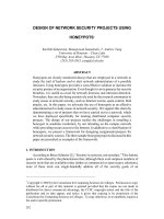
There are many types of breakwater structures used throughout the world. As shown in Table
2.1, breakwaters can be classified into three structural types: (1) the sloping or mound type, (2)
the vertical type which includes the basic (simple) vertical type and the composite and horizontally composite types, and (3) special types. Figure 2.1 shows conceptual diagrams of the different types of breakwaters.
Table 2.1 Structural types of breakwaters
Sloping (mound) type
Vertical (upright) type
Composite type
Rubble mound breakwaters
Rubble mound breakwaters (multi-layer)
Rubble mound breakwaters armored with blocks
Concrete block breakwaters
Reshaping rubble mound breakwaters (berm breakwaters)
Reef breakwaters (submerged breakwaters)
Monolith concrete breakwaters
Block masonry breakwaters
Cellular block breakwaters
Concrete caisson breakwaters
New caisson breakwaters
Horizontally composite type
Special (non-gravity) type
Curtain wall breakwaters
Steel pile breakwaters
Horizontal plate breakwaters
Floating breakwaters
Pneumatic breakwater
Hydraulic breakwater
(1) Sloping or mound type
The sloping or mound type of breakwaters basically consist of a rubble mound as shown in Fig.
2.1(1). The most fundamental sloping type breakwater is one with randomly placed stones (a).
To increase stability and decrease wave transmission, as well as to decrease material costs, the
multi-layered rubble mound breakwater was developed having a core of quarry run (b). The
stability of the armor layer can be strengthened using shape-designed concrete blocks, while
wave transmission can be reduced using a superstructure (wave screen or wave wall), which can
also function as an access road to the breakwater (c).
Breakwaters comprised of only concrete blo~ks (d) are also being constructed, especially for use
as a detached breakwater providing coastal protection. Although wave transmission is not reduced so much for this breakwater type, its simple construction procedure and the relatively
high permeability of the breakwater body are advantageous features. Recently, reef breakwaters
or submerged breakwaters (e) have been constructed for coastal protection, while not to interrupting the beautiful "seascape."
3
Reshaping breakwaters (f) utilize the basic concept of establishing an equilibrium between the
slope of the rubble stone and wave action, i.e., the
rubble mound forms an Se-shape slope to stabilize
itself against wave actions. This breakwater has a
large berm in front, which will ultimately be
reshaped due to wave actions, and therefore it is
called the berm breakwater or dynamically stable
breakwater. It should be noted that this concept is
not new, since ancient rubble mound breakwaters
were all of this type, being naturally reshaped by
damage and subsequent repairs.
(QI~
(d)
;ill
v
(2) Vertical type
(e)
(composite and horizontally composite types)
The original concept of the vertical breakwater
was to reflect waves, while that for the rubble
(f)
mound breakwater was to break them. Figure
2.1(2) shows four vertical type breakwaters having
different mound heights. The basic vertical wall
Fig. 2.1 (1) Sloping type breakwaters
breakwater is shown in (a), while the others are
(0)
H.wL.S7~.
composite breakwaters with a rubble mound foundation,
_~L."",:,
"Z
namely, the low-mound (b) and high-mound composite
---'-----breakwaters (d). By convention, the high-mound composite breakwater has a mound that is higher than the low
water level (L.W.L.).
The former breakwater does not
cause wave breaking on the mound, while the latter one
does. Since the high-mound composite type is unstable due
to wave-generated impulsive pressure and scouring caused
HWL. S7
(c)
by breaking waves, composite breakwaters with a lowLWL.
"7
mound are more common. The composite breakwater with
a relatively high mound (c) that is lower than L.W.L. occasionally generates impulsive wave pressure due to wave
breaking.
~
To reduce wave reflection and the breaking wave force on
the vertical wall, concrete blocks are placed in front of it.
Fig. 2.1 (2) Vertical type
This is called a composite breakwater covered with wavebreakwaters
dissipating concrete blocks, which is now called the
horizontally composite breakwater. Such breakwaters are not new, however, since vertical wall
breakwaters suffering damage to the vertical walls were often strengthened by placing large
stones or concrete blocks in front of them so as to dissipate the wave energy and reduce the
wave force, especially that from breaking waves. Modern horizontally composite breakwaters
employ shape-designed concrete blocks such as tetrapods.
4
The horizontally composite breakwater is very similar to
a rubble mound breakwater arrnored with concrete blocks.
Figure 2.1(3) shows how its cross section varies with
mound height, where as the mound height increases, the
breakwater becomes very similar to rubble mound
breakwaters. In particular, a breakwater with core stones
in front of the vertical wall (d) is nearly the same as the
rubble mound breakwater. They are basically different,
however, since the concrete hlocks of the rubble mound
breakwater act as the armor for the rubble foundation,
while the concrete blocks of the horizontally composite
breakwater function to reduce the wave force and size of
the reflected waves. Thus, horizontally composite
breakwaters are considered to be an improved version of
the vertical types.
(0 )
(b)
(d)
Fig. 2.1 (3) Horizontally
composite breakwaters
Figure 2.1(4) shows several kinds of composite breakwaters having different upright sections. An upright wall
with block masonry (b) was initially most popular, in
which many different methods were applied to strengthen
the interlocking between the blocks. Cellular blocks (c)
have also been used to form the upright wall of vertical
breakwaters. However, the invention of caissons (d) made
these breakwaters more reliable, and many were subsequently constructed around the world. Caisson breakwaters have been improved using sloping top caissons (e)
or perforated walls (f).
(0)
(b)
(c)
It should be noted that the rubble mound/rubble foundation of composite breakwaters is vital to prevent the
failure of the upright section by scouring, as well as stabilizing the foundation against the wave force and caisson
weight.
(el
(3) Special types
Special type breakwaters are those employing some kind
of special feature. Although they are not commonly used,
their history is long, and in fact, some were constructed
in ancient times. Special breakwaters, however, do not
always remain special, because some of them later
become a standard breakwater, e.g., the perforated caisson breakwater has become very popular in some countries and is now considered to be a standard breakwater
there.
5
If)
Fig. 2.1 (4) Composite
breakwaters
Common special type breakwaters are non-gravity type
ones, such as the pile, floating, or pneumatic types. These
breakwaters also have a long history, and some are still
being currently employed. Their uses though, are limited
to special conditions.
Figure 2.1(5) shows some special breakwaters. The curtain wall breakwater (a) is commonly used as a secondary
breakwater to protect small craft harbors, and the vertical
wall breakwater having sheet piles or continuous piles (b)
is sometimes used to break relatively small waves. A horizontal plate breakwater (c) can reflect and break waves, and
as shown, it is sometimes supported by a steel jacket. A
floating breakwater (d) is very useful as a breakwater in
deepwaters, but its effect is limited to relatively short
waves. The pneumatic breakwater (e) breaks the waves due
to a water current induced by air bubble flow, and it is
considered effective for improving nearby water quality,
though only being effective for waves having a short
length.
(0)
(b)
(c)
~
~
(e)
(4) Breakwater selection
Breakwaters are selected based on considering the
items listed in Table 2.2. Their influence on the
surrounding topography due to wave reflection and
on the environmental water conditions also help
determine which type of breakwater structure
should be used.
(5) Comparison of sloping and vertical types
Each type of breakwater has advantages and disadvantages. Lamberti and Franco (1994) discussed
the advantages and disadvantages of using a caisson breakwater (composite breakwater) in comparison with a rubble mound breakwater armored by
concrete blocks. The advantages are summarized as
follows:
t
...::<::..:. ~.~.:.4.~'"
.. .
,~
.",
,"
.'
b
Fig. 2.1 (5) Special
breakwaters
Table 2.2 items to be considered
in the selection of breakwaters
(1) Layout of breakwaters
(2) Environmental conditions
(3) Utilization conditions
(4) Executive conditions
(5) Costs of construction
(6) Construction terms
(7) Importance of breakwaters
(8) Available construction materials
(9) Maintenance
a) A smaller body width/quantity of material
This is one of the biggest advantages of using a composite breakwater, which makes the breakwater construction more economical, especially in deep water. In addition, a small breakwater
width limits the impact on seabed life and increases the usable water area.
b) Reduced maintenance
6
The composite breakwater requires less maintenance because the blocks of rubble mound
breakwaters require relatively frequent maintenance efforts.
c) Rapid construction, reduction of failure during construction, and smaller environmental
impact during construction
The composite breakwater can be rapidly constructed and is fully stabilized once its caissons are
filled with sand. In comparison, the rubble mound breakwater is more unstable since a longer
period occurs in which its inner layers may be subjected to the damage during construction. In
addition, since not much quarry work or damping is required, the general public is not disturbed
as much and the environment is damaged less.
d) Miscellaneous
Reuse of the dredged material, potential removability, and fewer underwater obstacles are also
considered to be advantages of using composite breakwaters. Moreover, use of a vertical breakwater may be only the choice if the availability of rubble stones is limited.
The advantages associated with using rubble mound breakwaters are summarized as follows:
a) Use of natural material
The use of natural material is a big advantage for the rubble mound breakwater since this reduces
material costs, especially when a large supply of rubble stones is readily available.
b) Use of smaller construction equipment
The construction of rubble mound breakwaters can be done from land, and does not usually
require large-scale construction equipment such as work barges.
c) Less environmental impact due to smaller reflected waves and more water exchange
Waves are absorbed by the rubble mound breakwater and long period waves such as tidal waves
are transmitted through it, which reduces the harm done to the environment.
d) Creation of a natural reef
The slope of the rubble mound breakwater provides an suitable place for sea life to live.
It should be noted that some of the disadvantages of composite breakwaters can be improved by
using horizontally composite breakwaters or perforated wall caissons.
7
2.2 Historical Development of Breakwaters
The value of "lessens learned" in actual breakwater design and construction methodology
cannot be stressed enough. It is for this reason that the historical development of breakwaters
will be described next, being a brief review of the work by Ito (1969) concerning the history of
breakwaters, as well as including additional recent developments.
2.2.1 Historical Breakwaters
(1) Breakwaters in ancient times
Breakwaters constructed in ancient times were presumably simple mounds made from stones.
However, as early as 2000 B.C., a stone masonry breakwater was constructed in Alexandria,
Egypt. Figure 2.2 shows a rubble mound breakwater located in Civitavecchia, Italy, which was
constructed by the Roman Emperor Trajanus (A.D. 53-117) and is recognized as being the
oldest existing rubble mound breakwater. This breakwater reached its equilibrium slope after a
long history of damage and subsequent repairs.
1--270--~j
\.8
Fig. 2.2 Rubble mound breakwater in Civitavecchia
(2) Modern breakwaters
The age of modern breakwaters is thought to have started in the latter half of the 18th century,
corresponding to the industrial revolution. The breakwaters built in Cherbourg, Plymouth, and
Dover are considered to be the pioneers of modern-day breakwaters.
a) Breakwater at Cherbourg
The construction of a bay-mouth breakwater at Cherbourg Port, France, which faces the mainland V.K. began in 1781. The breakwater's initial design was a rock-filled breakwater with a
50-m cone-shaped crib. However, the large cones failed soon after installation, and so in 1978
its design was changed to a rubble mound breakwater. The slope was 1/3 in the initial plan,
although after frequent damage and repairs, it leveled out at 1/8. The upper part, above L.W.L.,
suffered frequent damage, and in 1830 a vertical wall was erected above this level. It is probably
the first high-mound composite breakwater. Changes in the breakwater's cross section are
shown in Fig. 2.3.
HWL. v
LWL.~_
-100
Fig. 2.3 Cherbourg breakwater
8
(3) Rubble mound breakwater at Plymouth
The breakwater in Plymouth Port, U.K., which runs along the English Channel facing Cherbourg
Port, was started in 1812. It was a rubble mound type which copied the rubble mound breakwater
at Cherbourg. The initial cross section is shown in Fig. 2.4, where the crown elevation is +3 m
and the slope 1/3. The crown elevation was later changed to +6 m to reduce wave overtopping.
The cross section of the breakwater was changed after suffering various damage and repairs. The
slope wasleveled to 1/5 in 1824, and stone pitching was added above L.W.L. Its cross section in
1841 is also shown in Fig. 2.4, having a berm near L.W.L. and a width of 110 m. This breakwater continued to require a great amount of additional stones even after the work done in 1841.
The slope reached 1/12 in 1921, which is close to the equilibrium slope. Dedicated maintenance
has ensured the breakwater's existence.
(a)
1812
+3.0
+5.7
:!: 0
-13.7
Fig. 2.5 Dover breakwater
;/,
Fig. 2.4 Plymcuth breakwater
(4) Vertical wall breakwater at Dover
Figure 2.5 shows the original design (1847) of the vertical wall breakwater located at Dover,
U.K. Factored into the design were the lessens learned from the Cherbourg and Plymouth rubble
mound breakwaters, as well as the limited supply of quarry-stones available near Dover. Erection of this vertical wall breakwater was extremely difficult; thus its construction was slow and
performed at great expense. This appeared to "payoff" since the breakwater experienced only
slight damages after completion. A half century later, the construction speed was significantly
improved when another vertical wall breakwater was built in the adjacent area.
2.2.2 Composite Breakwater (from high- to low-mound)
Many high-mound composite breakwaters were built after the construction of the Cherbourg
breakwater. In the U.K., composite breakwaters were also built in places such as St. Catherine
and Alderney.
Wave action on the rubble mound causes scouring of the mound and makes the vertical wall
unstable. To avoid this type of damage, the scouring area may be covered with large stones or
blocks, or the wall may be placed at a lower level. The breakwater in Alderney was changed
9
from a high-mound breakwater to a lowmound one, while the river-mouth breakwater in Tyne was also changed from a
high- to a low-mound composite breakwater, and finally in the 1890's, to a vertical
breakwater without a rubble foundation. The
breakwater in Peterhead is a very lowmound composite breakwater with a mound
level of -13.1 m. Figure 2.6 shows cross
sections of these breakwaters.
St Catherine
(0 )
-;- 9,3'7
Alderney (- 95m)
(b)
Alderney (- 2o.0m)
Such composite breakwater technology was
applied throughout the world, with lowmound composite breakwaters being subsequented erected in the ports of British
colonies, e.g., Karachi, Colombo, and
Madras.
(c)
2.2.3 Rubble Mound Breakwater Armored
with Blocks
In parallel with the development of comFig. 2.6 Change of mound height
posite breakwaters, rubble mound breakwafrom high to low
ters showed very impressive developments
owing to the invention of concrete blocks.
The primitive cement that appeared
around 3000 B.C. was significantly Algiers North
1"5,0
improved in the 18th and 19th centuries. One major improvement occurred in 1824 when J. Aspdin
invented portland cement.
(1) Breakwaters in Algeria
The historical port of Algiers dates
- 33,0
back to the 16th century. The port's
breakwater was a rubble mound
Fig. 2.7 Algiers north breakwater
breakwater which required continuous maintenance. In 1833, a French engineer, Poirel, carried out reinforcement work using 6000
m 3 of 2- to 3-m 3 stones, but the stones ended up being unstable. The breakwater was later
successfully reinforced using 20-m 3 rectangular concrete blocks.
Figure 2.7 shows the cross section of the north breakwater in Algiers in 1840. Its cross
section then was similar to modern breakwaters, having core stones armored with 15rn' concrete blocks. The concrete blocks, with a slope of 1/1, saved much materials
compared to the Plymouth type of rubble mound breakwaters.
10
(0 )
1859
Rubble mound breakwaters armored with
concrete blocks were built in ports in Algeria
(Algers, Oran, Philippeville, etc.) from the
middle to the end of the 19th century. These
breakwaters, however, suffered from damage
due to the steep slope, insufficient weight of
concrete blocks, insufficient depth of the armor
layer, and rough placing of blocks.
1869
(Damage)
(b)
-12.4
-16.0
'/1
1869
Figure 2.8 shows changes in the cross section
of the breakwater at Oran, which suffered from
damage in 1869 because its armor layer was
not extended to a sufficient depth. Even though
the arm or layer depth was changed to -9.5 m
in the improved cross section, the breakwater
still experienced much subsequent damage. A
Marseille type cross section was therefore
adopted as the extension part, which will be
described later.
(c)
(Redesigned)
(d)
Extension
-9.5
Fig. 2.8 Breakwater at Gran
Figure 2.9 shows changes in the cross section
of the breakwater built at Philippeville. It
experienced much damage, even during construction, which gradually led to improving the
cross section. To increase its stability, a large
superstructure was incorporated.
1860
(0)
1865 (bl
+45
s
~'
Al?;;;~O
(2) Marseille type
Extension of the outer port of Marseille,
France, started in 1845. Both vertical and
rubble mound breakwaters were constructed
there. Its rubble mound breakwater (Fig. 2.10)
was very strong and included the following
special features:
.";>
, 'f/
1869 (e)
1878 (d)
a) The stones of the breakwater core vary in
weight, with lighter stones being placed in the
inner core.
b) An armor layer of concrete blocks is included and extends to a sufficient depth. The armor
layer above sea level has a gentle slope that
dissipates waves, and the superstructure is
placed at distance away from the water with
most of it being covered with armor blocks.
-16.0
1890
(e)
Fig. 2.9 Breakwater at Phillippeville
11
+8.4
Marseille
- 6.0 "-L.L'
-'-=-¥
-14.0
Fig. 2.10 Marseille breakwater
c) The slope of the lower level is relatively steep.
d) The armor blocks are installed carefully.
(a)
+95
Many breakwaters copied the cross section of the
Marseille breakwater, and they are called the
Marseille type.
+4.0
(3) Shape-designed concrete blocks
The Marseille type breakwater was not only
popular for use in the Mediterranean but also in
other seas. Its design, however, has drawbacks,
e.g., the armor concrete (rectangular) block is
very heavy and the cross section tends to be large
because of the mild slope above sea level.
Shape-designed concrete blocks such as the
tetrapod, which was conceived by P. Danel in
Fig. 2.11 Change of armor blocks at Safi
1949, were subsequently invented to improve the
rubble mound breakwater.
Figure 2.11 shows cross sections of the Marseille type rubble mound breakwater and a rubble
mound breakwater in Safi, Morocco, annored with 25-t tetrapods. It is considered that the latter
breakwater reduced the required amount of concrete by 70% and stones by 5%. This breakwater
showed its solid construction when it withstood a heavy storm in 1957 that produced 9-m
waves.
2.2.4 Step-Type Breakwater and Composite Breakwater
(1) Step-type and composite breakwaters in Italy
Another type of rubble mound breakwater was developed in Italy (Fig. 2.12), namely, a rubble
mound breakwater having a step-type arrnor layer was designed by Parodi and constructed as the
Galliera breakwater in Genoa, Italy. This step-type annor layer was considered to be more stable
owing to the interlocking network of uniformly piled concrete blocks. Many breakwaters of this
type were built in the 1880's and 1890's, but they were not so successful. In fact, the Galliera
breakwater suffered damage in 1898, with one of the causes being due to settlement, especially
differential settlement of the rubble mound.
12
(a)
Genoa·Gall iera
+37
2
':-
+85
.
Naples- St. Vincenzo
~
'
\
'Z-
-6,= -
•
?
~,
Catania
+74
" Cyclopean
Naples' Granil i
(Head)
+8.5
<"0'
J',J.-~7~.o~'~'i1i~i~~
.~
' oS
~'7,c.'~~w
- 22.5,
-..-.-,,4J~~il~_:2.~_~~~::,,,,- 35.0
../ ,:;;;::;;Y;;
(e)
(b)
Steep Slope.
Cellular
(d)
Naples (detached)
+70
(c)
Composite
type
J
Fig. 2.12 Change from step-type to composite breakwater.
In Naples, a step-type breakwater was adopted as the breakwater head of the St. Vincenzo
breakwater. The breakwater had a steep stepped wall to increase stability. If the step becomes
very steep, it looks similar to the vertical wall of a composite breakwater. Many composite
breakwaters were constructed at that time in the U.K., and the associated technology was transferred to Italy; thereby making this composite breakwater the predominant one after 1900. One
noteworthy composite breakwater was a detached (island) breakwater erected in Naples (Fig.
2.12).
(2) Cyclopean blocks and caissons
To increase the stability of the vertical wall, large blocks were used to build it. The Granill
breakwater in Naples employed cellular blocks, but their installation led to problems. For
example, these blocks were not stable during installation, and therefore, rapid construction was
required.
The composite breakwater at Catania, Italy, adopted huge 330-t Cyclopean concrete blocks as
the vertical wall. The word "Cyclopean" comes from "Cyclops," who according to Greek
mythology was a giant with a single eye in the middle of his forehead.
The composite breakwater built in Italy
affected later designs of other breakwaters in the Mediterranean. The Mustafa
breakwater constructed in Algiers in
1923 adopted the composite breakwater
design with cyclopean blocks. Sainflou
designed a cyclopean block composite
breakwater design to be used as the
outer breakwater in Marseille (Fig.
2.13), with each cyclopean block
weighing 450 t and interlocking with
-~~~'----I
Fig. 2.13 Cyclopean block breakwater
designed by Sainflou
13
each other through projections. This design,
however, was not adopted, although a similar
type composite breakwater was built from 1930
to 1953 in Marseille. Figure 2.14 shows changes
in the cross section of this breakwater. The interlocking network was further reinforced as a
design improvement.
+ 60
The vertical wall of a composite breakwater
can be constructed using a caisson, which
increases its stability. Walker proposed the use
of a caisson in the 1840's, and in 1886, Kinipple proposed using a concrete caisson reinforced by iron members. A metal caisson was
employed in Bilbao, Spain, in 1894, and was
later adopted in several other ports. Concrete
caissons were also erected in Barcelona,
Spain, and other ports, while reinforced concrete caissons were employed, vice using a
rock-fill crib, around 1901 in America's Great
Lakes. In Japan, the reinforced concrete caisson was used for the first time in Kobe in 1907.
It is clear that the caisson promoted further
development of composite breakwaters throughout the world.
1933"'35
(b)
1937
(c)
Fig. 2.14 Cyclopean block
breakwater at Marseille
(3) Wave-dissipating blocks
The composite breakwater can be reinforced by placing wave-dissipating blocks in front of the
vertical wall, with Fig. 2.15 showing such breakwaters. The wave-dissipating blocks are rectangular concrete blocks which are the same as those used for the armor layer of the rubble
M~
-::=z----Wove- dissipot ing
I
,.)1 yheod
(0 )
+135
-,
30
-
=
.,
Ymuiden
Mormugoo
+65
Colombo
+3.5
A=~:&:
Buffalo
(I)
Poli
(9 )
-+67
Civilovecchio
+92
(h)
05·~41-;.
_.:1&i{j}h~'~I-r---='-~'lfid;l'til~;:"..-L~m!i
-75
Fig. 2.15 Breakwaters with wave-dissipating blocks
14
mound breakwater.
Therefore,
the
breakwater cross section looks similar to
Agha (Alger)
l'
5.5
rubble mound breakwaters armored with
concrete blocks.
Although the concrete
blocks were usually placed after breakwater
damage occurred, in some breakwaters they
were incorporated into the initial design.
Fig.2.16 Wave screen at Agha breakwater
Figure 2.16 shows the Agha breakwater in
Algiers, which has a wave screen, i.e., a
vertical wall that reduces wave transmission
through the breakwater. This breakwater
and
a
composite
breakwater
with
wave-dissipating blocks are nearly identical,
but based on its design concept, this type of
breakwater is considered to be a rubble
mound breakwater having a large wave
crown (screen).
2.2.5
Revival of
Breakwater
the
Rubble
Old
+8.7+ 6.0
(~
Damage
1933
(b)
sz
Mound
Redesign
(c)
The development of breakwaters, which
started with the mild-slope rubble mound
breakwater, led to the prevailing worldwide
construction of the low-mound composite
breakwater.
However,
low-mound
breakwaters suffered from various types of
damage, and in Europe, damaged composite
breakwaters were changed into rubble
mound breakwaters.
+70
Reinforced
(d)
Fig.2.17 Revival of
breakwater at Catania
(1) Failure of the Catania breakwater
The composite breakwater built at Catania,
Italy, (Fig. 2.17) failed during construction
between1930 to 1931: a failure caused by
insufficient inter locking of the cyclopean
blocks. The breakwater was subsequently
reconstructed as a Marseille type rubble
mound breakwater.
15
rubble
mound
(2) Failure of the Leixoes breakwater
Figure 2.18 shows changes in the breakwater at Leixoes, Portugal. The original breakwater was a
Marseille type rubble mound breakwater. The breakwater, designed in 1932, was a composite type
breakwater which failed during construction between 1934 to 1936. The redesigned breakwater
was still a Marseille type, but the constructed breakwater was a rubble mound breakwater having
large concrete blocks
Old (1884--- 92)
(0)
====:;;;j
New Design (1932)
TI05
(b)~~o
Proposed (1936)
(cl
Fig.2.18 Revival of rubble mound breakwater at Leixoes
2.2.6 Recent Development of Rubble Mound Breakwaters
(1) Rubble mound breakwaters armored with shape'designed concrete blocks
The development of breakwaters up to the middle of the 20th century has been described. Recent
developments in rubble mound breakwaters are largely based on using shapedesigned concrete
blocks. Many successful rubble mound breakwaters were made using armor layers comprised of
such blocks. The design methods for rubble mound breakwaters were established and summarized
in books and manuals; e.g., the Shore Protection Manual, in which the Hudson formula was
introduced as the standard design method for the armor layer. In addition, high-speed,
computer-assisted numerical analysis and physical model experiment technology has also
supported the enhanced development of rubble mound breakwaters.
Figure 2.19(a) shows the cross section of the Sines breakwater built in Portugal. This is a typical
rubble mound breakwater constructed with shape-designed concrete blocks. Note that the cross
section is quite small even though the water depth is deeper than 30 m and the design significant
wave height is higher than 10 m. The employed shape-designed concrete block is the Dolos block,
which has high interlocking strength, and enables a more economical design by reducing the
amount of required materials.
It was very surprising that this breakwater suffered serious damage in 1978. The break down of
Dolos blocks is thought to be one of the main causes of failure, since they are relatively weak
16
although their interlocking strength is high.
occurred during those ages.
Several failures of rubble mound breakwaters also
\a)
Wave Wall
_ .._. __ ~ m
1/2-lt Stone
42t Dolos
3
~
16-20tStone
2
Care Moterial
--
9-20t 1/2-6t
4
-25.0m
4-3
Bed rock
fT
W
OLayers 90t Blacks
Battom LoyerRobloc'
150m _ Tap Layer "Anfifer"
-------l
(b)
One Layer 90t
"Robtoc-
+1500
.:!-700
I
1
0.00
IT·--t - - - - - 1.3
-20.00
Existing Slope
Fig.2.19 Sines breakwater (Brunn, 1985)
The redesigned cross section of the Sines breakwater has an armor layer made from
low-interlocking blocks and a mild slope (Fig. 2.19(b». Its cross section is very similar to that of
19th-century rubble mound breakwaters armored with concrete blocks.
After such failures, major efforts were directed at improving the design method ofthe rubble mound
breakwaters, as well as associated experimental techniques. These succeeded in reestablishing
the design method, which is summarized in recently published books and manuals, e.g.,
CIRAlCUR(1991), and includes van der Meer's new formula for designing the armorlayer.
(a)
Lake Side
Harbor Side
Test B7 Protile S
!---;-Test B7 Praflle2
(DeSign Profile
/
/
.(
I
/J
_~-
.-"
20
. ::..':"-i-~~
/"
•
.--/
///
L..-:='-_
~ Breakwater
1
~'O
<,
CORE
"'-
0
'-,
...........................................
---------
<,;::-
- - "'-=Existlng Horbor Bottom
May 1987 Survey Cross Section
200 fram North End of Federal Breakwater
May 1987 Survey Cross Section
100 from North End of Federal Breakwater
10
-':-':..-20
Elevatian
Feel Above
Lake Michigan
Low Water Datum (LWDJ
Horbor Side
Desion Water Leve~20
/45 FI.LW9L' 10
I
.....
CORE
,I
,,?
~'~Xisting Harbor Bottom
-e-
0
10
EI:Va~o~O
Feel Above
Lako Mlchgon
Low Water Datum(LWDJ
Fig.2.20 Berm breakwater at Rachine, Michigan (Montgomery et al., 1987)
17
(2) Berm breakwaters
Figure 2.20 shows the cross section of a breakwater built in Racine, Michigan. This breakwater
has a large berm in the front part of the breakwater, though the quarry stones are not very large.
Such a design allows for berm deformation which will end up forming an equilibrium slope. Berm
breakwaters like these have been built in North America, Europe, and other places, and many
studies have been carries out on them (Willis et al., 1987; Baird and Hall, 1984; Fournier et al.,
1990; Burcharth et al., 1987, 1988). Note that the berm breakwater resembles much older rubble
mound breakwaters, e.g., the Plymouth breakwater.
2.2.7 Recent Developments in Composite Breakwaters
Figure 2.21 shows one of the first modern breakwaters built in Japan in 1897: the north breakwater
at the Port of Otaru designed by Hiroi. Many breakwaters constructed in Europe around this time
were rubble mound breakwaters or composite breakwaters with block masonry. The technology
introduced into Japan was primarily related to the composite breakwater, which has been developed
into the currently used caisson composite breakwater. In Italy and other countries facing the
Mediterranean Sea, caisson breakwaters were gradually being developed based on the technology
available at the end of the 19th century. The development of composite breakwaters following
1945 was rapid due to the advancement ofthe design technology for concrete structures and that of
in-sea construction technology using large working vessels.
12 tf
unit: m
Fig.2.21 Otaru breakwater
The current status of composite breakwater technology is summarized as follows (Tanimoto et al.,
1994):
(1) Design method of conventional composite breakwaters
The design technique for composite breakwaters is nearly established, and includes the calculation
method for determining the wave forces acting on the breakwater and the design method used for
its caisson members.
(2) Horizontally composite breakwaters
The composite breakwater covered with wave-dissipating blocks is an improved version of the
conventional composite breakwater, and is now frequently being constructed, especially in breaker
zones.
18
(3) New caisson breakwaters
Many new types of breakwaters have been invented and commercialized in order to mitigate the
drawbacks associated with conventional composite breakwaters.
a)Perforated wall
One new caisson breakwater IS the
perforated wall caisson breakwater invented
by Jarlan (1961). Figure 2.22 shows this type
of breakwater in Comoeau bay(Cote and
Simard 1964). The caisson dissipates wave
energy by the front perforated wall and wave
chamber. Therefore the caisson is also called
the wave dissipating caisson. The perforated
wall caisson breakwater is usually employed
with in a bay having relatively small waves
since the forces on the caisson members are
relatively small in such area. This type of
construction also meets the need for
providing low reflectivity.
~
I
Jl
':~,
Fig.2.22 Perforated wall caisson breakwater in
Comeau bay
Many breakwaters of this type were subsequently constructed throughout the world. The first
perforated wall breakwater in Japan was constructed at Takamatsu Port in 1970(Fig. 2.23) Since
then, perforated wall caissons have often been employed as breakwaters or quaywalls, with much
effort having been made to improve their stability and function in breakwater applicationstOkada
et al. 1990) Establishing the design method has also been a key study area.
Figure 2.24 shows a perforated wall caisson breakwater incorporating a vertical slit wall. This
caisson was constructed at the Port ofYobuko, Japan, and is a modified version of a perforated wall
caisson having an opening that passes from the front to rear side; thus improving the efficiency of
seawater exchange.
Figure 2.25 shows the curved slit caisson breakwater at Funakawa Port. The caisson has a curved
slit wall as a perforated wall which is reinforced by prestressed concrete to be able to resist against
severe storm waves.
Figure 2.26 shows a cross section of the baymouth breakwater constructed in Kamaishi Bay. The
maximum depth at the bay-mouth is 63 m, making the breakwater there the deepest in the world.
The lower part ofthe caisson has a trapezoidal shape to obtain a wide bottom, which decreases the
eccentric load on the rubble mound. Its upper part has a wave-dissipating structure consisting of
double horizontal slit walls. In general, the trapezoidal caisson suits deep water sites.
Figure 2.27 shows the dual cylinder caisson breakwater being constructed at the Port of Shibayama,
which also has deep water, as well as large waves. This breakwater caisson consists of inner and
outer cylinders.
The cylinder wall is a kind of shell structure that can withstand large forces with
19
a relatively small cross section. Since the caisson is cylindrical as a whole, the total amount of
required construction material is reduced. The upper part of the outer cylinder consists of a
perforated wall, and the sections between the inner and outer cylinders constitutes a wave chamber
that forms the wave-dissipating structure. The design method for the dual cylinder caisson
breakwater is almost fully established, with much data being obtained from a demonstration
experiment carried out at Sakaiminato (Tanimoto et al. 1992). Figure 2.28 shows the dual cylinder
caisson breakwater at Nagashima, where the calm water area behind the breakwater is used for
recreational and aquaculture purposes.
9.90
3.9
HWL to 2.50 r'
A
~H.H.W.L+320
~
8-8
6.00
A-A
+4:51A
7
Z
o
o
..s; L.w.L + 0.20
Perforateol Wall
(!j
-7
.
Fig.2.23 Perforated wall caisson breakwater at Takamatsu Port
Seaward Side
10.5
Harbor Side
+4.3l0 4.51.04.51
4 H.WL~2.55 ~
LW L.! 0.00
.
Perforated Wal L,/
'\Z
Wave Chamber
.:5.0
~~,-,jj
-9.4
Fig.2.24 Perforated wall caisson breakwater at Yobuko Port
unit: m
Fig.2.25 Curved slit wall caisson breakwater at Funakawa Port
20
19.0
Seaward Side
lOO
H.W.L.+1.50
Harbor Side
+6.0 +3.0
-600
Fig.2.26 Deepwater breakwater at Kamaishi Port
Seaward Side
+8.5
;....r_--+
DO 0 0
00 0 0
-.¥~------_"":"":"'-to 0 0
0
0000
A,'
unit: m
Fig.2.27 Dual cylinder caisson breakwater at Shibavama Port
Fig.2.28 Dual cylinder caisson breakwater at Naaashima Port
21