A study on obstacle avoidance in autonomous robot system using robotics system toolbox
Bạn đang xem bản rút gọn của tài liệu. Xem và tải ngay bản đầy đủ của tài liệu tại đây (779.01 KB, 6 trang )
HAPPY NEW YEAR 2018
A STUDY ON OBSTACLE AVOIDANCE IN AUTONOMOUS ROBOT SYSTEM
USING ROBOTICS SYSTEM TOOLBOX
LUU HOANG MINH
Faculty of Electrical and Electronic Engineering, Vietnam Maritime University
Abstract
In robotics, obstacle avoidance is the task of satisfying some control objective subject to
non-intersection or non-collision position constraints. Normally obstacle avoidance is
considered to be distinct from path planning in that one is usually implemented as a reactive
control law while the other involves the pre-computation of an obstacle-free path which a
controller will then guide a robot along. In this paper, a TurtleBot, which is an open-source
personal research robot platform, will be introduced to create an obstacle avoiding system.
To control the robot avoid obstacles, the coordinate data from the laser sensor will be
received and calculated the distance from all obstacles to robot for finding the direction of
the closest obstacle. Based on that, robot direction control command will be decided by
using robotics system toolbox and MATLAB program.
Keywords: TurtleBot, obstacle avoiding, robotics system toolbox, MATLAB.
Tóm tắt
Trong robot học, tránh chướng ngại vật là nhiệm vụ phải thỏa mãn một số mục tiêu ràng
buộc trong điều khiển như tránh những vị trí giao cắt với các đối tượng di động hoặc tránh
va chạm với đối tượng cố định. Thông thường, phương pháp tránh chướng ngại vật khác
biệt với phương pháp bám quỹ đạo, tránh chướng ngại vật thường được thực hiện dưới
dạng một luật điều khiển các phản ứng của robot, trong khi phương pháp bám quỹ đạo liên
quan đến việc tính toán trước đường đi của robot. Trong bài báo này, tác giả sẽ giới thiệu
một phương pháp điều khiển robot tự hành tránh chướng ngại vật sử dụng TurtleBot. Để
điều khiển robot tránh chướng ngại, dữ liệu tọa độ từ cảm biến laser của robot sẽ được sử
dụng để tính khoảng cách từ tất cả các vật cản đến robot và xác định được hướng của vật
cản gần nhất. Dựa vào đó, một ứng dụng tự động điều khiển robot thay đổi hướng tránh
vật cản được lập trình bằng cách sử dụng MATLAB và bộ chương trình robotics system
toolbox của MATLAB.
Từ khóa: TurtleBot, tránh chướng ngại vật, robotics system toolbox, MATLAB.
1. Introduction
The ability to detect and avoid obstacles quickly is an important design requirement for all
application of autonomous robot system. In the past, a lot of solutions have been proposed for this
problem. But most of these solutions demand a heavy computational load, which makes them very
difficult and cannot use to control a low-cost robot system.
This paper presents the results of a research aimed to presented a new method for obstacle
avoidance relying on low cost robot with laser sensors, and involving a reasonable level of
calculations, so that it can be easily used in real time control applications. The Cartesian coordinates
signal from laser sensor will be used to calculate distance from robot to all obstacle, and the index
number of this signal will decide the signal to control the robot.
Besides this introduction, the structure of the present paper is as follows:
Section 2 introduces about TurtleBot and robot system configuration;
Section 3 contains a description of the obstacle avoidance solution to control robot by using
signal from laser sensor;
Section 4 presents the experimental results used for evaluating the system.
2. System configuration
TurtleBot is a low-cost, personal robot kit with open-source software. With TurtleBot, we can
build a robot that can drive around our house or our office, and have enough horsepower to create
exciting applications [1].
Journal of Marine Science and Technology
No. 53 - January 2018
15
HAPPY NEW YEAR 2018
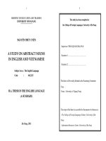
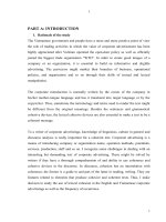
The Figure 1 shows the TurtleBot of Willow
Garage. TurtleBot is an open source hardware project
as described by the Open Source Hardware Statement
of Principles and Definition v1.0. Open source
hardware is hardware whose design is made publicly
available so that anyone can study, modify, distribute,
make, and sell the design or hardware based on that
design. The hardware's source, the design from which
it is made, is available in the preferred format for
making modifications to it. Ideally, open source
hardware uses readily-available components and
materials, standard processes, open infrastructure,
unrestricted content, and open-source design tools to
maximize the ability of individuals to make and use
hardware. Open source hardware gives people the
freedom to control their technology while sharing
knowledge and encouraging commerce through the
open exchange of designs. Hardware of TurtleBot is
shown as following table.
Figure 1. TurtleBot of Willow Garage
Table 1. TurtleBot technical specifications
MOBILE BASE AND POWER BOARD
Platform:
Yujin Kobuki
Battery:
Up to 4400mAh Ni-lon
User Power:
5V and 19V at 1A
12V at 1.5A
12V at 5A
TURTLEBOT HARDWARE
Mechanical:
Mounting hardware
TurtleBot structure
Module Plate with 1 inch spacing hole pattern
Electrical:
Modified Kinect cable for Kokuki access
ON-BOARD 3D SENSING
Sensor:
ASUS Xtion PRO
Specs:
640x480 @ 30 frames/sec
Range:
0.8 - 3.5m
Gyro:
110 degrees/sec, Factory Calibrated
ON-BOARD NETBOOK
Processors:
Intel Core i3-4010U
Memory:
4G
HDD:
500GB
Connectivity:
USB, Wi-Fi, Ethernet,VGA, HDMI, SD card
The robotic software of TurtleBot includes
Ubuntu OS and Robotic operation system (ROS).
ROS
is
a
collection
of
software
frameworks for robot software
development.
There are more than 2,000 packages, going from
diverse robotic platforms, and passing from
hardware drivers to many computer algorithms.
ROS is a collection of tools, libraries, and
conventions that aim to simplify the task of
creating complex and robust robot behavior
across a wide variety of robotic platforms.
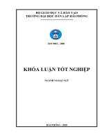
Figure 2 showed the hardware diagram. In
Figure 2. Hardware diagram
TurtleBot, the net-book is connected with Kobuki base and Kinect sensors by USB cables. Kinect
sensor contains a laser sensor, it measures the coordinates of obstacle. When battery is low, robot
can charge by direct power cable or through docking station.
To control TurtleBot, a master computer (host) is used. The host and TurtleBot must be
connected to the same wireless local area network.
There are two methods to control TurtleBot:
16
Journal of Marine Science and Technology
No. 53 - January 2018
HAPPY NEW YEAR 2018
The host is installed Ubuntu OS and ROS;
The host uses Window OS and MATLAB program with Robotics system toolbox.
In this research, the second method is used to build an application of obstacle avoiding system.
3. Obstacle avoidance algorithm
This part introduces an obstacle avoidance algorithm to control TurtleBot. The data from laser
sensor [2÷4] is used to control robot for avoiding obstacles. The coordinate data from the sensor will be
received by net-book of TurtleBot. After that, this data will be send to the host to calculate the distance of
all obstacles to the robot and obtain the minimum distance and index of minimum and maximum
distances. If the minimum distance is bigger than a fix distance, which is called threshold distance, the
robot will move forward. If the minimum distance is smaller than threshold, the robot will turn with spin
and back up slight velocities. The process will be repeated until the robot has other order.
Table 2. Laser sensor specification
Range
110 degrees with minimum distance is 50 cm
Data type
Array (Cartesian coordinates of obstacle)
Size of data
Over 500 scan points (depend on material of obstacle)
Table 2 and Figure 3 showed the laser sensor specification. Because the laser sensor cannot
detect a near distance object, about 20 cm from the robot to object, so in our program, the threshold
distance is 30cm, it means that when the robot moves to obstacle with distance from laser sensor to
obstacle is 30 cm, the robot will turn to other direction. The distance from sensor to obstacle can be
calculated as following:
distance = √x2 +y2
(1)
where, x and y is Cartesian coordinates of obstacle.
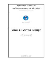
Besides that, the index of laser data increases from right position to left position, so the
obstacle avoiding program has three cases as follows:
Case 1: The robot approaches to obstacle from the right side (Figure 4). In this case the
minimum distance index is smaller than the maximum distance index; the robot will be controlled to
turn to the left side.
Figure 3. Laser data indexes
Figure 4. The robot approaches to obstacle
from right side
Case 2: The robot approaches to obstacle from the left side (Figure 5). In this case the
minimum distance index is bigger than the maximum distance index; the robot will be controlled to
turn to the right side.
Case 3: The robot moves to the corner (Figure 6). In this case the maximum distance index is
in the middle range of data size; the robot will be controlled to turn to the left side with big angle.
Figure 5. The robot approaches to obstacle
from left side
Journal of Marine Science and Technology
Figure 6. The robot moves to the corner
No. 53 - January 2018
17
HAPPY NEW YEAR 2018
An obstacle avoidance program was created with three cases above. The Figure 7 shows the
flowchart of obstacle avoidance program.
Begin
Begin
Enter
Enter TurtleBot
TurtleBot IP
IP address
address
Define
Define parameter
parameter for
for obstacle
obstacle avoiding
avoiding
(Angular
(Angular velocity;
velocity; forward
forward velocity;
velocity; Backward
Backward
velocity;
velocity; Distance
Distance threshold)
threshold)
Initialize
Initialize ROS
ROS
(Connect
(Connect to
to the
the TurtleBot)
TurtleBot)
Create
Create aa publisher
publisher for
for the
the robot's
robot's velocity
velocity and
and create
create aa message
message for
for velocity
velocity
robot
robot == rospublisher('/mobile_base/commands/velocity');
rospublisher('/mobile_base/commands/velocity');
velmsg
velmsg == rosmessage(robot);
rosmessage(robot);
Subscribe
Subscribe to
to the
the topic
topic /scan
/scan
laser
laser == rossubscriber('/scan');
rossubscriber('/scan');
Receive
Receive scan
scan data
data
scan
scan == receive(laser)
receive(laser)
Receive
Receive coordinates
coordinates from
from all
all obstacle
obstacle
data
data == readCartesian(scan)
readCartesian(scan)
Compute
Compute distances
distances from
from Robot
Robot to
to all
all obstacles
obstacles (dist)
(dist)
Compute
Compute size
size of
of distances
distances data
data (n)
(n)
Compute
Compute distance
distance of
of the
the closest
closest (MinDist)
(MinDist) and
and farest
farest
(MaxDist)
(MaxDist) obstacles
obstacles
and
and data
data indexes
indexes (Minindex,
(Minindex, Maxindex)
Maxindex) of
of thore
thore distances
distances
Closest
Closest distance
distance << Distance
Distance threshold
threshold
0
0
Control
Control robot
robot
continue
continue on
on forward
forward
path
path with
with forward
forward
velocity
velocity
1
MaxIndex<(n2/-50)
MaxIndex<(n2/-50) OR
OR MaxIndex>(n/2+50)
MaxIndex>(n/2+50)
(Not
(Not move
move to
to corner)
corner)
0
Control
Control robot
robot left
left spin
spin
with
with 44 times
times of
of Angular
Angular
velocity
velocity
1
MaxIndex>MinIndex
MaxIndex>MinIndex
(Robot
(Robot moves
moves to
to obst.
obst. from
from
right
right side)
side)
0
1
Control
Control robot
robot back
back up
up
slightly
slightly and
and left
left spin
spin with
with
Angular
Angular velocity
velocity
Control
Control robot
robot back
back up
up
slightly
slightly and
and right
right spin
spin with
with
negative
negative Angular
Angular velocity
velocity
Stop?
Stop?
1
End
End
Figure 7. The flowchart of obstacle avoidance algorithm
The control signal is created by using MATLAB program and tranfer to robot base on wifi
network. After communication between robot and the host succeeded, the TurtleBot can be
controlled by publishing a message. For example, the linear velocity is controlled by typing following
commands [5]:
18
Journal of Marine Science and Technology
No. 53 - January 2018
HAPPY NEW YEAR 2018
robot = rospublisher('/mobile_base/commands/velocity')
velmsg = rosmessage(robot)
velmsg.Linear.X = 0.1;
% meters per second
send(robot,velmsg);
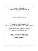
4. Experimental result
(a) The robot moves to the obstacle
(b) The robot turn to other direction
(c) Image from robot’s camera
Figure 9. TurtleBot avoids the wall
Figure 8 shows the way the robot escapes the corner. When the distance between laser sensor
and the door is 30 cm and the maximum distance index is in the middle range of data index, the robot
will automatic change its direction following the red line.
The second obstacle is the wall. The robot also avoids the wall perfect with the direction is the
red line in Figure 9.
(a) The robot moves to corner
(b) The robot finds the way to escape
(c) Image from robot’s camera
Figure 8.TurtleBot escapes the corner
Journal of Marine Science and Technology
No. 53 - January 2018
19
HAPPY NEW YEAR 2018
5. Conclusion
This paper presented the obstacle avoidance method using signal of laser sensor. From above
results these following conclusion are given:
(1) The method demands very low computational load, and can be implemented on low-cost
autonomous robot and can be easily adapted for other sensors, like sonar sensors, infrared sensors;
(2) The robot could avoid any kind of static obstacles, and even some moving obstacles with
low velocity;
(3) The robot performs very well on narrow zone (Figure 8);
(4) The method can be combined with some control theory such as fuzzy logic control or neural
networks, etc., to control robot more smoothly and exactly.
REFERENCES
[1] Willow Garage, “TurtleBot”, URL: .
[2] MediaWiki, "OpenKinect", URL: , 2013.
[3] Ayrton Oliver, Steven Kang, Burkhard C. Wünsche, Bruce MacDonald, "Using the Kinect as a
Navigation Sensor for Mobile Robotics", IVCNZ ’12, Dunedin, New Zealand, November 2012.
[4] K. Khoshelham. “Accuracy Analysis of Kinect Depth Data”. In ISPRS Workshop Laser Scanning,
volume 38, 2011.
[5] Luu Hoang-minh, Park Young_san. “A study on TurtleBot Controll using Matlab Program”, The
Korean Society of Marine Engineering, 10/2015.
Received:
Revised:
Accepted:
20
10 January 2018
22 January 2018
28 January 2018
Journal of Marine Science and Technology
No. 53 - January 2018