Thin film morphology of block copolymer PS-PMMA blends with homopolymer PLA
Bạn đang xem bản rút gọn của tài liệu. Xem và tải ngay bản đầy đủ của tài liệu tại đây (2.45 MB, 8 trang )
Research
THIN FILM MORPHOLOGY OF BLOCK COPOLYMER PS-PMMA
BLENDS WITH HOMOPOLYMER PLA
Nguyen Thi Hoa*, Nguyen Manh Tuong
Abstract: Blends of poly(styrene)-block-poly(methyl methacrylate) (PS-b-PMMA)
and poly(lactide) (PLA) were deposited in the form of thin films on the surface of
modified silicon wafers and exposed to tetrahydrofuran (THF) vapor annealing. It was
shown that in specific experimental conditions, a core-shell morphology consisting in
cylinders with a PMMA shell and a PLA core, within a continuous matrix of PS, was
formed. In this case, PLA naturally segregated in the core of the PMMA cylinders,
minimizing the PS/PLA interaction, which constitutes the most incompatible pair. The
selective extraction of the PLA yielded to porous domains with small dimensions (6±2.5
nm), reaching the performances that are currently attained in highly incompatible
block polymers with low molecular weight.
Keywords: Thin films, Homopolymer/block polymer blends, Solvent annealing, Core-shell morphology.
I. INTRODUCTION
The phase behavior of block polymers can be notably modified by the addition
of homopolymers. When the macrophase is avoided, when the homopolymer is
incorporated into the existing domains, changes in the dimensions can arise (one of
the domains is swollen) but also new morphologies can be formed. This has been
carefully investigated by numerous studies, from a theoretical point of view1-2 and
experimentally demonstrated in the bulk3-5 and in thin films6-10. Starting from a
given block polymer composition that normally dictates the type of morphology at
equilibrium, it is thus possible to tune the properties of the self-assembly by
homopolymer addition, expanding the possibility to generate various template
geometry with tailored dimensions. From a practical point of view, this is
particularly interesting in the field of the elaboration of nanoporous templates
where a simple costless homopolymer addition would render possible a fine tuning
of the morphology (instead of a cumbersome and costly library of block polymers
with various dimensions and compositions).
Among the various block polymer systems considered for applications within
such approach, PS-b-PMMA currently represents the industrial standard.20-24. For
this polymer, it has been well demonstrated that homopolymer addition such
PMMA6,7,8 or PEO9 in a cylinder-forming PS-b-PMMA was able to modify the
dimension of the domains formed. Interestingly, depending on the system
composition and molar weight of the added homopolymer, new core/shell
morphology could be formed and from such organization, Jeong et al demonstrated
the possibility to generate sub-10 nm porosity with selective extraction of the
PMMA.10 In this work, we have examined the possibility to modify the
morphology of a typical PS-b-PMMA system with PLA. Despite an abundant
literature devoted to block polymer/homopolymer blends, such system has not
been yet considered to our knowledge. Compared to other types of modifiers, PLA
represents a material with a growing interest due to its renewable sources and the
ease of its selective degradation with dilute base, that would leave totally
Journal of Military Science and Technology, Special Issue, No.51A, 11 - 2017
77
Chemistry & Environment
unaffected the PS and PMMA domains in contrast to PS-b-PMMA/PMMA blends
where the extraction of the PMMA would potentially results in surface
reconstruction due to the PMMA block swelling. In addition, PLA displays higher
level of incompatibility towards PS than PMMA, allowing for sharper behavior in
comparison to PS-b-PMMA/PMMA (or even PS-b-PMMA/PEO) system.
2. MATERIALS AND METHOD
2.1. Materials
Poly(lactide) (PLA), homopolymers and PS-b-PMMA, P(S-r-MMA) block
polymers were purchased from Polymer Source Inc. Tetra Ethyl Ortho Silicate
(TEOS) and all used solvents were purchased from Sigma Aldrich and used as
received. Si(100) substrates of 10*10 mm² were cleaned by sonication in
dichloromethane, methanol and distilled water for 10 minutes each.
2.2. Thin films preparation
PS-b-PMMA/PLA blend: a 10 mg.L-1 solution of PLA (16 kg.mol-1) in acetone
or toluene was prepared and mixed in appropriate amounts to a 20 mg.L-1 solution
of PS-b-PMMA (101 kg.mol-1, fPMMA=0.3) in toluene to prepare blends with
homopolymer concentrations (vol/vol %) of 1, 5, 10 and 15% in the dry state
(based on the density of each component). The resulting solution mixtures were
agitated overnight before being deposited by spin coating (2,500 rpm) onto
modified silicon wafers with a P(S-r-MMA) (14 g.mol-1) brush on top (to prepare
the modified substrates, a thin layer (approx.10 nm) of P(S-r-MMA) was firstly
deposited onto clean silicon wafers, heated under vacuum at 170°C for 48h and
rinsed in toluene). Homopolymer/block polymer thin films with a thickness
between 60 and 70 nm were obtained using this procedure (thicknesses were
measured by imaging a scratched area in AFM tapping mode). After deposition,
thin films were exposed at 25°C to THF vapors in a closed vessel (150 mL)
containing 5 mL of THF for 5 and 10 minutes (Fig.1).
Closed vessel
Thin film
5mL of THF
Fig.1. Schematic representation of solvent vapor annealing.
2.3. Atomic force microscopy (AFM)
AFM in the tapping mode was carried out in air at room temperature with a
Nanoscope III from Digital Instruments Corp in Department of Chemistry, NANO
Systems Institute, Seoul National University, Korea. Silicon cantilevers Tap300
from Budget Sensors with integrated symmetrical pyramidal tips (15 µm high)
with no Al coating backside, a nominal spring constant of 42 N.m-1 and a
78
N. T. Hoa, N. M. Tuong, “Thin film morphology of … with homopolymer PLA.”
Research
resonance frequency between 300–400 kHz were used. All the displayed AFM
images are height images taken in tapping mode. Characteristic lengths (diameter
and center-to-center distance) were extracted from 2D line cut. Each dimensions
provided is the result of multiple measurements.
2.4. Selective removal of the component
PLA was selectively degraded by placing the sample in a 0.5 M sodium
hydroxide solution containing 40/60 (by volume) methanol/water for 30 min. After
being removed from the solution, the samples were washed with a 40/60 (by
volume) methanol/water solution. PMMA was selectively removed by exposing
the thin films to UV radiation (254 nm) during 60 hours (lamp power: 0.10 mJ/s)
and further immersion of the irradiated films into concentrated acetic acid for 20
minutes and finally rinsed in distillated water.
2.5. Inorganic replication of the porous films
The silica precursor solution (TEOS:H2O:EtOH:HCl) with a molar proportion
of 1:5.5:21:0.005 was prepared by mixing 26.5 ml EtOH, 1mL deionised water,
1.25 mL HCl 0.1M and 5 ml TEOS and stirring at least during 16 hours at room
temperature. The porous PS films were immerged in the solution allowing for the
infiltration of the porosity by the liquid silica precursors.11 After withdrawal,
samples were then heated at 450°C during 5 minutes to provoke the precursor
condensation and the elimination of the polymer template to yield the silica
replicas. Depending on the deposition conditions (withdrawal speed), the formation
of a dense silica roof layer above the porous replica could be obtained.12 This was
exploited to prepared mechanically robust samples for the cross sectional views.
3. RESULTS AND DISCUSSION
3.1. Film morphology as function of the homopolymer addition
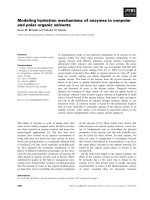
Figure 2 shows the surface morphology of thin films of PS-b-PMMA (101
kg.mol-1, fPMMA=0.3) / PLA (16 kg.mol-1) blends obtained by casting a solution
prepared by mixing a solution of PS-b-PMMA in toluene with a solution of PLA in
acetone. Surface topography is shown for the as casted samples and after 5 and 10
minutes of solvent vapor exposure. The absence of macroscopic phase segregation
suggests that the incorporation of the PLA is homogenous in the studied range of
the composition (up to 15%). We observed that the incorporation of the
homopolymer in the block polymer was dependent on the deposition conditions.
Figure S2 (Electronic Supplementary Information) shows several examples of as
spun morphologies with homogenous and heterogeneous dispersions. Using
chlorobenzene as the solvent for both the block and the homopolymer led to a
macroscopic phase separation (Figure S2c and S2f). In contrast, solvent mixture
(toluene/THF and toluene/acetone) promoted a homogenous dispersion of the
homopolymer in the block polymer self-assembled pattern (Figure S2a-b and
Figure S2d-e). In fact, we will demonstrate later that the PLA is incorporated in the
minor PMMA domains (as one can already deduce from the visible increase in size
of the segregated phases observed in Figure 2).
Journal of Military Science and Technology, Special Issue, No.51A, 11 - 2017
79
Chemistry & Environment
As spun
THF 5 min
THF 10 min
0%
1%
5%
10%
15%
Fig. 2. AFM height images of PS-b-PMMA/PLA thin films deposited on P(S-rMMA) modified substrates as a function of the amount of PLA and THF vapor
annealing time. All images are 0.5 x 0.5 µm² (scale bar is 100 nm),
z scale bar is 0-10 nm.
The absence of macrophase separation in the blend can be explained on the
basis of the miscibility properties of the component. Acetone or THF, which are
80
N. T. Hoa, N. M. Tuong, “Thin film morphology of … with homopolymer PLA.”
Research
good solvent for PMMA and PLA (but not for PS), will promote the segregation of
these two components, forming micelles like structures (with a PS corona) at
nanoscopic scale as the solvent evaporates.
As observed in Figure 2, as spun neat PS-b-PMMA thins films do not exhibit
clear ordered nanostructuration, due the fast evaporation of the solvent and the
rather low chemical incompatibility of the PS and PMMA blocks. Adding PLA in
the system does not improve the order in the as spun state, but clearly the
microphase separation is enhanced as judged by the increase in contrast of the
images (particularly after 5%). After exposure to solvent vapors, the
nanostructuration is improved. Hexagonal array of dots or fingerprint
morphologies formed depending on the exposure time and amount of PLA added.
Despite the use of a neutralized substrate that normally promotes the formation
of a perpendicular orientation of the PMMA domains, the presence of PLA favored
the formation of parallel orientation. When the proportion of PLA is above a
certain threshold (between 1 and 5 % for 10 min. exposure; 5 and 10 % for 10
minutes), the presence of the latter drives the orientation of the domains. This
suggests that the neutralized substrate is specific for PS and PMMA composition
but not for PLA. We, and others, have already demonstrated that such transition is
strongly driven in the swollen state, by the affinity of the domains towards the
interfaces. When polymers display different swelling extent they will exhibit
different response towards a surface field even if the surface energy of the
polymers is similar. The swelling extent of PS, PLA and PMMA measured under
THF vapors (same conditions than Figure 2) showed that PLA swells slightly more
than the other counterparts (1.8 for PLA vs 1.6 for PS and PMMA) indicating that
the delicate surface energy balance between PS/PMMA domains and the interface
favoring the perpendicular orientation is prone to perturbation in presence of PLA.
The characterization of the actual morphology, as well as the localization of the
polymer phases was carried out using specific polymer extraction (hydrolysis
under mild alkaline solution for PLA and UV exposure followed by acetic acid
extraction for PMMA). The resulting porous polymer film was examined by AFM
and subjected to replication in order to assess the internal structuration of the film
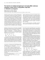
and fully confirm the morphology adopted.This is shown in Figure 3 where the two
typical nanostructurations (dots in Figure 3a and fingerprint in Figure 3f) were
successively exposed to PLA removal, PMMA removal and replication of the
resulting porosity.
In the case of the dots morphology, the first PLA extraction forms small
depressions located in the center of the circular domains, indicating that the PLA is
located in the middle of the PMMA domains (Figure 3b). Further extraction of the
PMMA domains enlarge the pores diameters (Figure 3c). The final resulting
porosity (after PLA and PMMA removal) was replicated by infiltration with solgel precursors followed by a brief thermal treatment in order to provoke the
condensation of the precursors and the pyrolysis of the polymer phase.
Journal of Military Science and Technology, Special Issue, No.51A, 11 - 2017
81
Chemistry & Environment
(a)
(d)
d)
(c)
(b)
(e))
Si Substrate
(f)
(i)
(g)
(h)
(j)
Si Substrate
Fig. 3. AFM height images of PS
PS-bb-PMMA/PLA:
PMMA/PLA: after 5 min of exposure in THF
vapors (a), after 10 min of exposure in THF vapors (f), after PLA extraction (b,g),
after PLA and PMMA extraction (c, h). SEM image of the silica replica of the
porous films obtained after PLA and PMMA extraction for the dot (top view (d) and
lateral view (e)) and the fingerprint mor
morphology
phology (top view (i) and lateral view (j)).
All AFM images are 0.5x0.5µm² (scale bar 100nm), with z scale 00--10
10 nm (except c
and j: 25 nm). Scale bare for SEM images is 300 nm in all images. In Figure e and j,
the dashed lines are guides for the eyes for tthe
he silicon surface and the silica upper
layer (from bottom to top) and arrows point the cylinder silica replicas.
The top (Figure 3d) and side view (Figure 3e) of the obtained replica reveal an
array of perpendicular pillars (covered by an upper layer in tthe
he case of the cross
sectional view to ensure the mechanical stability of the replica upon fracture – see
experimental part), indicating that the parent porosity and therefore, the initial
morphology, can be depicted as an array of vertical cylinders. For the fingerprint
morphology, the selective removal of PLA (Figure 3g), followed by the PMMA
82
N. T. Hoa, N. M. Tuong
Tuong,, “Thin
“Thin film morphology of … with homopolymer PLA
PLA.””
Research
extraction (Figure 3h) indicates that the PLA is similarly located in the center of
the PMMA. The replication confirmed the presence of parallel cylinders as seen on
the top (Figure 3i) and side (Figure 3j) views. For this latter, the observed structure
can be described as an array of collapsed solid cylinders in contact, resulting from
the elimination of the continuous phase.
4. CONCLUSIONS
In this work, the morphology of thin films of PS-b-PMMA/PLA blends has
been examined. For a PS-b-PMMA with a standard molar weight (101 kg.mol-1)
we examined the influence of the type of solvent used for the deposition, the
concentration and molar weight of PLA as well as the behavior of the obtained
films upon solvent vapor annealing. In some conditions, hexagonally packed
core(PLA)-shell(PMMA) cylinders, oriented perpendicularly to the substrate,
within a continuous matrix of PS were formed. This allowed the formation of
porous domains with extremely small dimensions (6±2.5 nm) after selective
extraction of the PLA, reaching the performances that is currently attained in
highly incompatible block polymers with low molecular weight. Such core/shell
morphology was obtained when PLA segregated in the core of the PMMA
cylinders, minimizing the PS/PLA interaction, which constitutes the most
incompatible pair.
REFERENCES
[1]. Markoff, J. IBM.Discloses Working Version of a Much Higher-Capacity Chip. The
New York Times, July 9 2015, p B2.
[2]. Mansky, P., Chaikin, P.,Thomas, E. L. Monolayer Films of Diblock Copolymer
Microdomains for Nanolithographic Applications J Mater. Sci. 1995, 30, 1987-1992.
[3]. Koo, K.; Ahn, H., Kim, S.-W., Ryu, D.Y.; Russell, T.P. Directed Self-Assembly of
Block Copolymers in the Extreme: Guiding Microdomains from the Small to the
Large Soft Matter 2013, 9, 9059-9071.
[4]. Jeong, S. -J., Kim, J. Y., Kim, B. H., Moon, H. -S., Kim, S. O. Directed SelfAssembly of Block Copolymers for Next Generation Nanolithography Mater. Today
2013, 16, 468-476.
[5]. Choksi, R.; Ren, X. Diblock Copolymer/Homopolymer Blends: Derivation of a
Density Functional Theory Physica D 2005, 203, 100-119.
[6]. Likhtman, A. E., Semenov, A. N. Theory of Microphase Separation in Block
Copolymer/Homopolymer Mixtures Macromolecules 1997, 30, 7273-7278.
[7]. Hashimoto, T., Tanaka, H., Hasegawa, H. Ordered Structure in Mixtures of a Block
Copolymer and Homopolymers. 2. Effects of Molecular Weights of Homopolymers
Macromolecules 1990, 23, 4378-4386.
[8]. Tanaka, H., Hashimoto, T. Ordered Structures of Block Polymer/Homopolymer
Mixtures. 3.Temperature Dependence Macromolecules 1991, 24, 5713-5720.
[9]. Tanaka, H. , Hasegawa, H. , Hashimoto, T. Ordered Structure in Mixtures of a Block
Copolymer and Homopolymers. 1. Solubilization of Low Molecular Weight
Homopolymers Macromolecules, 1991, 24, 240-251.
Journal of Military Science and Technology, Special Issue, No.51A, 11 - 2017
83
Chemistry & Environment
[10].Matsen, M. W. Phase Behavior of Block Copolymer/Homopolymer Blends
Macromolecules 1995, 28, 5765-5773.
[11].Gamys, C. G., Vlad, A.; Bertrand, O., Gohy, J.-F. Functionalized Nanoporous Thin
Films From Blends of Block Copolymers and Homopolymers Interacting via
Hydrogen BondingMacromol. Chem. Phys. 2012, 213, 2075-2080.
[12].Mishra, V. Hur, S. Cochran, E. W., Stein, G. E., Fredrickson, G. H., Kramer, E. J.
Symmetry Transition in Thin Films of Diblock Copolymer/Homopolymer
BlendsMacromolecules 2010, 43, 1942-1949.
TÓM TẮT
HÌNH THÁI HỌC CỦA MÀNG MỎNG TRÊN CƠ SỞ HỖN HỢP
COPOLYMER PS-PMMA VÀ HOMOPOLYMER PLA
Hỗn hợp của polystyren-bloc-polymetylmethacrylat (PS-PMMA) và
polylactid (PLA) được lắng đọng dưới dạng màng mỏng trên bề mặt silicon
biến tính và tái cấu trúc bằng phương pháp tiếp xúc với hơi tetrahyfrofuran
(THF). Hình thái học của vật liệu được đánh giá bằng phương pháp kính hiển
vi nguyên tử lực (AFM) và kính hiển vi điện tử quét (SEM). Kết quả hình thái
vỏ-lõi bao gồm các xi lanh sắp xếp hình lục giác với vỏ PMMA, lõi PLA trên
nền PS đã được hình thành. Sự loại bỏ chọn lọc PLA tạo ra màng rỗng với
những lỗ nhỏ kích thước 6 ± 2,5 nm sắp xếp theo trật tự hình lục giác.
Từ khóa:Màng mỏng, Hỗn hợp copolymer/homopolymer, Tiếp xúc hơi dung môi, Cấu trúc vỏ-lõi.
Received date, 20th Aug., 2017
Revised manuscript, 27th Sept., 2017
Published, 1st Nov., 2017
Address:
Institute of Chemistry Materials, Academy of Military Science and Technology,
17 Hoang Sam, Cau Giay, Hanoi, Vietnam.
*
Email:
84
N. T. Hoa, N. M. Tuong, “Thin film morphology of … with homopolymer PLA.”