Analytical modeling of nonlinear behavior of masonry infills in reinforced concrete frame buildings under seismic action
Bạn đang xem bản rút gọn của tài liệu. Xem và tải ngay bản đầy đủ của tài liệu tại đây (1.35 MB, 9 trang )
RESEARCH RESULTS AND APPLICATIONS
ANALYTICAL MODELING OF NONLINEAR BEHAVIOR OF
MASONRY INFILLS IN REINFORCED CONCRETE FRAME
BUILDINGS UNDER SEISMIC ACTION
Nguyen Le Ninh1*, Phan Van Hue2
Abstract: The presence of masonry infills significantly affects to the seismic response of reinforced concrete (RC) frame structures. However, in the modern seismic codes, this issue has not been specifically
addressed, especially when the structures are allowed to work beyond the elastic limit. The paper introduces
a nonlinear behavior model of the masonry infills that the authors have set up and it has been applied to
evaluate the seismic response of RC frames designed according to modern conception when considering
the interaction with the masonry infills. The results of nonlinear static analysis show that the masonry infills
are likely to cause a sudden collapse of the structures, override the seismic design of the structures and
undermine the efforts of the designers.
Keywords: Masonry infills, reinforced concrete frame, nonlinear static analysis, nonlinear behavior model,
interaction.
Received: September 15th, 2017; revised: October 30th, 2017; accepted: November 2nd, 2017
1. Introduction
Masonry infills significantly affect to the surrounding frame under seismic actions. It has been well - known
that masonry infills increase the stiffness, strength and energy-dissipation capacity… of the structural frames under lateral loads. The research results have also induced a better understanding of the behavior of infilled frames
in different loading phases and then many models have been proposed, especially for elastic phase [1-4].
Nowadays, many changes have been taken place in the seismic design conception that transferred
from designing for protecting the buildings to designing for protecting directly not only the human but also the
social materials. It implies that the elastic limit of the structure is allowed to be exceeded during earthquakes
with moderate or high intensity, without the occurrence of abrupt collapse [5]. In this situation, it is essential
that the nonlinear behavior of the masonry infills and the interaction between them and the surrounding
frame in different working phases under the horizontal impact should be adequately studied [6].
In the following sections, research results about the nonlinear behavior of the masonry infills and their
influences on the seismic response of RC frame structures according to modern conception will be presented.
2. Modeling behavior of the reinforced concrete frame and the masonry infills
In the present study, the nonlinear static (pushover) analysis is selected for seismic performance
estimation purposes of the building. With regard to the constitutive laws for the materials, the classical parabola-rectangle diagram has been adopted for the concrete under compression, and an elastic-hardening
diagram has been adopted for the reinforcing steel through by [7]. The nonlinear behavior of columns and
beams was described according to a lumped plasticity approach, in which the frame elements are elastic, all
the nonlinearities are concentrated at the end-sections of the elastic beams, in a flexural plastic hinge that
is defined by [8]. Acceptance criteria for deformation for components corresponding to the target Building
Performance Levels of Collapse Prevention (CP), Life Safety (LS), and Immediate Occupancy (IO) are also
given in [8]. The drift values are usually used to illustrate the overall structural response associated with
various structural performance levels. The drift values of 1%, 2% and 4% corresponding to structural performance levels of IO, LS and CP were suggested by [9].
Asso.Prof.Dr, Faculty of Building and Industrial Construction. National University of Civil Engineering.
PhD student, MienTrung University of Civil Engineering.
* Corresponding author. E-mail:
1
2
JOURNAL OF SCIENCE AND TECHNOLOGY IN CIVIL ENGINEERING
Vol. 11 No. 6
11 - 2017
13
RESEARCH RESULTS AND APPLICATIONS
2.1 Model of nonlinear behavior of the masonry infills
The specialized scientific documents for nearly 70 years have introduced many models simulating
the behavior of the masonry infills in the RC frame under the horizontal impact in the elastic phase. When
increasing lateral loads, the behavior of the RC frame-masonry infills transfers from linear to nonlinear because of the material nonlinearities of the infill panel, the surrounding RC frame, and the panel-frame interfaces. The nonlinear effects mentioned above introduce analytical complexities which require sophisticated
computational techniques to be properly considered in the modeling. These facts complicate the analysis
of infilled frame and represent one of the main reasons to explain why the modern seismic codes, example TCVN 9386:2012, don’t provide any specific provisions of how to consider the infill-frame interaction,
although masonry infills’ influence is strongly admitted on the overall response of the buildings, especially
when the RC frame is allowed to work after the elastic limit [10].
In recent times, some models aimed at evaluating the hysteretic behavior of the infilled frame have been
found. Among different approaches, two of those proposed by [2,11] are remarkable. These models based on
the equivalent diagonal strut idea, used in linear analysis
and displacement - force relations are established on the
basis of experimental test results. For this reason, the accuracy and the applicability of the proposed model are limited. To resolve this existing problem, a nonlinear behavior
model of the masonry infills in the RC frame has been
developed by the authors based on research results of [1].
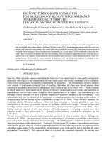
To develop the idea of the preceded authors, the
proposed model has still been based on the equivalent diagonal strut model but the equivalent strut's width wm that
was suggested by [1] varies during the bearing process
(Fig. 1). Whereby, the equivalent diagonal strut's width is
determined according to the following expression [1,5]:
Figure 1. The equivalent diagonal strut model
(1)
where m is the factor that depends on the characteristics of the masonry infills (m = 2 for clay brick masonry
infills, m = 3.6 for aerated autoclaved concrete masonry infills); n = V/Vmu is the ratio of the horizontal force
and the ultimate horizontal strength; wm0 is the basic width of the equivalent strut at the time the masonry infills hypothetically are not enough strength and stiffness to participate in bearing with the surrounding frame:
(2)
In the above formulation, λh and λl are the parameters of the lengths of contact zh, zl between the infill
and column, beam given by the following expressions:
(3)
where Em and Ec are the elastic modulus of the masonry infill and concrete, respectively; l and h are the
length of beam and the height of column, measured between the centerlines of the columns and the beams,
respectively; lm, hm, dm and tm are the length, the height, the diagonal length and the thickness of the infill,
respectively; Ib, Ic are the moment of inertia of the beam and the column, respectively; k is the factor that
depends on the characteristics of the masonry infills (k = 3.5 for clay brick masonry infills, k = 20 for aerated
autoclaved concrete masonry infills).
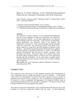
In this model (Fig. 2), the nonlinear behavior of the panel infills in the frame is modeled by the equivalent diagonal strut with a single plastic hinge in the middle. The form of the proposed model is similar to the
ones of models proposed by [2,11]. The relationship between the shear force Vm and the horizontal displacement of masonry infill Δm is composed by four phases, with the acceptance criteria for deformation of the masonry infill materials. The first phase represents the linear behavior of the infill that is depicted by the straight
line between point A (unloaded situation) and B (the effective yield point), with the stiffness Kmy. According to
[1], this phase ends when n = 0.6. The second phase (segment BC) represents the nonlinear behavior like
14
Vol. 11 No. 6
11 - 2017
JOURNAL OF SCIENCE AND TECHNOLOGY IN CIVIL ENGINEERING
RESEARCH RESULTS AND APPLICATIONS
the phenomenon of deformation hardening, with the
stiffness Kmu = βKmy is a fraction of the elastic stiffness
(β is the stiffness ratio between Kmu and Kmy). According to [1] this phase ends when n = 1.0. At point C, the
ordinate denotes the ultimate strength of infill and the
abscissa indicates the deformation when the strength
starts to decrease seriously (segment CD). Due to the
brittle failure of the masonry infill, the acceptance criteria for deformation for the infill corresponding to the
target building performance levels of LS and CP as
Figure 2. The Force-Displacement relationship
shown in Fig. 2 nearly coincide. The third phase is the
for the equivalent strut model
post - capping degrading phase, which runs from the
maximum strength to the residual strength. Its stiffness depends on the elastic stiffness, and is defined by
means of the parameter γ as Kmr = -γ.Kmy. It has been suggested that γ should be within the range of values
between 0.005 and 0.1, although the upper value corresponds to very brittle infill. After point D, the masonry
infill is characterized by the constant residual strength Vmr to enhance the numerical stability of the analysis.
The residual strength of masonry infill can be ignored by prolonging the segment CD until a zero residual
strength (dashed line in Fig. 2), corresponds to the displacement ∆mp. Thus, the calculation and the assessment of infills are carried out only at the two target building performance levels of IO and LS, in accordance
with the provisions of the current standards of many countries [8,9,12].
2.2 Define the lateral stiffness parameters of the masonry infills
Generally, the lateral stiffness of the masonry infills at different working phases is determined by the
following expression [1]:
(4)
where wm0 is the basic width of the equivalent strut that is defined by the expression (2); λh and λl are given
by the expression (3); θ is the slope angle of the panel’s diagonal to the horizontal.
- At the time the masonry infill is yields, n = 0.6:
(5)
- At the time the masonry infill reaches the ultimate strength, n = 1.0:
(6)
2.3 Define the strength parameters of the masonry infills
Based on the extensive investigations in last seven decades [3,13,14], four different failure models of
the infill panels viz., bed-joint sliding shear failure, cracking due to diagonal tension, compression failure of
diagonal strut, and corner crushing of infills, have been identified. Several models have been proposed for
evaluating strength of the masonry infills in these failure models. In the above failure models, bed-joint sliding shear failure and compression failure of diagonal strut are the most commonly identified failure models.
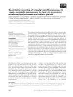
Figure 3. Cross section of considered frame (1st floor)
JOURNAL OF SCIENCE AND TECHNOLOGY IN CIVIL ENGINEERING
Vol. 11 No. 6
11 - 2017
15
RESEARCH RESULTS AND APPLICATIONS
The choice of method for determining the strength of the infills corresponding to each of their different
failure forms is a very important factor in order to determine the strength of the infills in accordance with
the purpose and scope of this study. The criteria used to select the strength of the infills for the nonlinear
behavior of the infills are as follows:
- The parameters used to determine the strength of the infills should be compliant with the current
Vietnamese technical standards;
- The infills are constructed by conventional clay brick masonry in Vietnam in the RC frame according
to the current technical provisions.
As is well-known, the strength of the infills depends on the geometrical and mechanical properties of
the materials as well as the infilled frame structure, therefore the infilled frame structure shown in Fig. 3 has
been considered to choose comparatively a suitable calculated method.
The 1st floor cross section of considered frame of the 10-storey RC frame building is represented
in Fig. 3. The frame is constructed of the B25 grade of concrete. The beams at the outermost span of the
frame (AB and CD spans) are infilled by 200mm thickness masonry that is constructed of plastic laminating
burnt clay bricks M75 and cement mortar M75. The physico-mechanical properties of the masonry infills and
the materials constituting the RC frame are defined in accordance with TCVN 5573:2011 [15] and TCVN
5574:2012 [16].
In the following section, the strength of the masonry infills at the characteristic points B, C, D and E
in the behavior model in Fig. 2 will be shown how to determine according to the collective research results
that have been realized about this issue.
2.3.1 The ultimate strength of masonry infill Vmu
The ultimate strength of masonry infill, Vmu, is the minimum value of strengths in the bed - joint sliding
shear failure model, Vms, and the compression failure of diagonal strut, Vmc:
(7)
Over the past 70 years, many researchers have proposed different models for determining the
strength of masonry infills in the sliding shear failure mode and compression failure of diagonal strut. Figs.
4 and 5 summarize the results of calculating the strength of masonry infills in accordance with the different
approaches in sliding shear failure and compression failure of diagonal strut.
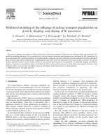
In Fig. 4, the results of strength of infill in the sliding shear failure model are calculated according to
different approaches that are in line with the chosen criteria: [17], [14], [3] with μ = 0.7 and μ = 0.3; [8,9,13];
[18], [12], [9]; the method is proposed by authors.
In Fig. 5, the results of strength of infill in the compression failure of diagonal strut are given by different approaches that are in line with the chosen criteria: [3,17], [14], [18], [12], [13], [4], [8].
Figure 4. Comparison of the strengths of infill in the sliding shear failure mode in accordance
with different approaches
Figure 5. Comparison of the strengths of infill in the compression failure of diagonal strut in accordance
with different approaches
The results in Figs. 4 and 5 show that there is a significant difference between values of strength of
the infill in accordance with the different approaches. Based on the analysis of the advantages and disadvantages of each method as well as the results obtained under the current conditions of application in Vietnam,
the models determining the ultimate strength of the infill are the ones proposed by the following researchers:
16
Vol. 11 No. 6
11 - 2017
JOURNAL OF SCIENCE AND TECHNOLOGY IN CIVIL ENGINEERING
RESEARCH RESULTS AND APPLICATIONS
a) The ultimate strength of masonry infills in the sliding shear failure model, Vms, which proposed by
the authors based on the bed-joint shear strength of the masonry unbraced shall be calculated in accordance with TCVN 5573:2011 [15]:
(8)
where fbs is the bond shear strength between brick and mortar; μ is the coefficient of friction for mortar - brick
interfaces; n1 = 1 for solid brick masonry, 0.5 for hollow brick masonry.
Expression (8) is established with the assumption that the masonry infill carries no vertical load due
to gravity effects, the clamping force across the potential sliding surface will be due only to the vertical component of the diagonal compression force in infill panel.
b) The ultimate strength of infill in the compression failure of diagonal strut is recommended by [8]:
(9)
where fmc is the compressive strength of the masonry.
2.3.2 The strength of the masonry infill at yielding Vmy
In Fig. 6, the results of strength of infill with the
same parameters as those in the previous section at
the beginning of yielding are calculated according to
different approaches that are in line with the chosen criteria: [1], [14], [20], [2], [12], [4]. Based on the analysis
of the calculated models, the equation proposed by [1]
was chosen because of its simplicity as well as the average calculated value compared to other approaches:
Figure 6. Comparison strength of the infill
at the beginning of yielding according to different
approaches
(10)
2.3.3 The residual strength of the masonry infill Vmr
The residual strength of the masonry infill Vmr is within the following limit [6]:
(11)
2.4 Define the displacement parameters of the masonry infills
The displacement of the masonry infill when it reaches the ultimate strength:
(12)
The displacement of the masonry infill at the first yield point:
(13)
The displacement of the masonry infill corresponds to residual strength Vmr:
(14)
Thus, this model that has established for nonlinear behavior of the masonry infills is based on the
experimental and analytical research results of [1] about the lateral stiffness and the strength at the beginning of yielding of the infills. Simultaneously, it is also based on the results of theoretical and empirical
research about the strength of different infills in RC frames corresponding to each type of failure models
gained by many researchers in the world. The parameters that used to determine the strength of infills are in
accordance with the current Vietnamese technical standards. This model has reflected the actual behavior
of the masonry infills in the various stages under the effect of horizontal loads. Thus, the model can be used
to evaluate the influence of the infills on the response of RC frame structures under the effect of this loads.
3. Nonlinear static analysis of the reinforced concrete frame structure designed
according to TCVN 9386:2012
3.1 Structural characteristics of the case study building
JOURNAL OF SCIENCE AND TECHNOLOGY IN CIVIL ENGINEERING
Vol. 11 No. 6
11 - 2017
17
RESEARCH RESULTS AND APPLICATIONS
Figure 7. The global geometry and reinforcements of the frame components
This numerical example is performed to evaluate the effect of the masonry infill on the nonlinear
response of the RC frame designed according to TCVN 9386:2012 [10] under the seismic action. The
frame is designed for ductility classes medium (DCM), the important factor γI = 1.25, built at the area with
the reference peak ground acceleration agR = 0.1097g, on the type D ground. The global geometry and the
basic dimensions of the frame are given in Fig. 7. The frame is constructed of the B25 grade of concrete,
the longitudinal reinforcement of beams and columns of group AIII, the transversal reinforcement of group
AI. On the beams at the outermost span of the frame (AB and CD spans) are infilled by 200mm thickness
masonry walls that are constructed of plastic laminating burnt clay bricks M75 and cement mortar M75. The
physico-mechanical properties of the masonry infills and the materials constituting the RC frame are defined
in accordance with TCVN 5573:2011 [15] and TCVN 5574:2012 [16]. The values of vertical load that act on
the beams at each floor in the seismic design situation, g + ψ2q, are alternately given by 22.1 kN/m (the side
spans of the transverse beam); 11.8 kN/m (the middle span of the transverse beam); 15 kN/m (the longitudinal boundary beams) and 19.8 kN/m (the longitudinal middle beams).
3.2 The response of the RC frame in the case of not considering the interaction between
frames and masonry infills
The RC frame structure is designed according to TCVN 9386:2012 under the seismic action. In the
case of not considering the interaction between the frame and the masonry infills (bare frame), the design
results for the reinforcements of the frame components are shown in Fig. 7. The nonlinear static analysis is
carried out by SAP2000, with the lateral force acting as forced displacements. It is assumed that flexural deformations control the nonlinear behavior of columns and beams. The analysis is performed until the frame
reaches the target displacement Δ = 1.348 m. Fig. 8a is the diagram of flexural plastic hinges that appear in
the frame at the time of taking place a hypothetical collapse. This figure shows that, without considering the
interaction between frame and masonry infills, the plastic failure mechanisms are expectedly happened with
flexural plastic hinges first appearing in the beams and then in the columns.
The solid line in Fig. 9 is the capacity curve that represents the nonlinear behavior of the bare frame.
This curve shows that the linear deformation of the frame ends at 10th step (V = 466.297 kN, ∆ = 0.126m).
Figure 8. Plastic deformation diagrams of the frame and masonry infills
a) bare frame; b), c), d) frame with infills of all floors; e), f) infilled frame without infills on the 1st floor
18
Vol. 11 No. 6
11 - 2017
JOURNAL OF SCIENCE AND TECHNOLOGY IN CIVIL ENGINEERING
RESEARCH RESULTS AND APPLICATIONS
The lateral stiffness of the frame in this stage Kbf
= 3700 kN/m. The maximum base shear force V =
726.13 kN and the horizontal displacement respectively ∆ = 0.559 m at 40th step. After this point, the
lateral stiffness of the frame almost linearly decreases. At the end of pushover progression at step 97, the
base shear force attains the value of V = 666.52 kN.
3.3 The response of the frame in the case of
considering the interaction between frames and
masonry infills
a) In case of having masonry infills in the 1st
and 3 side spans of the all floors
rd
In this case, to establish the nonlinear behavior model of the masonry infill, the parameters related
to the stiffness of the masonry infill types (wm0, Kmy,
Figure 9. Capacity curves
K*mu and Kmr) are given in Table 1. The parameters
related to the strengths as well as the displacement values of the masonry infills defined by the expressions
from (12) to (14) are given in Fig. 10.
Table 1. The stiffness parameters of the masonry infills
Parameters
wm0 (mm)
wm (mm)
K*mu (N/mm)
Kmy (N/mm)
Kmr (N/mm)
1 floor
609
1356
17046
37937
-2656
2nd ÷ 10th floors
575
1279
21555
47973
-3358
st
The results of the nonlinear static analysis show that, starting at the third loading step until the sixth
loading step, the masonry infills in turn from the first floor to the sixth one are deformed at different degrees
(LS and IO states). At the 8th step (V = 881.24 kN, ∆ = 0.113 m), the masonry infills of the three bottom floors
are collapsed together, leading to the appearance of yielding at the ends of the beams in the middle span of
the 1st floor and the 2nd floor while the masonry infills in the upper floors continue being plastically deformed
in different degrees (Fig. 8b). The plastic deformation at the bases of the first floor columns begins at the 10th
step (V = 954.302 kN and ∆ = 0.140 m) and continues increasing until 15th step when all the bases of the
first floor columns are yielded. Unlike bare frame, the upper butts of columns on the third floor are yielded
at 39th step (V = 793.077kN and ∆ = 0.463 m) (Fig. 8c). The infilled frame gradually approaches the collapse
state in accordance with soft story collapse mechanism nearly while in all the ends of the beams in the 3rd
floor only appear nonlinear deformations at LS state, in several ends of the beams in the 4th and 5th floors
only appear nonlinear deformations at IO state, the masonry infills in the 5th, 6th and 7th floors are plastically
deformed at IO and LS states as 10th step and total beams, columns and infills in the upper floors are remain
in the elastic limit. Until the target displacement reaches ∆ = 1.345 m, the plastic deformations are almost
focused on the bases of columns on the foundation surface and the butts of columns on 3rd floor (Fig. 8d).
The dashed line in Fig. 9 is the capacity curve of the frame with masonry infills at two side spans of
all floors. This curve has a completely different form from the capacity curve of the bare frame (solid line). In
the first stage until the base shear force reaches to V = 881.24 kN and ∆ = 0.113 m at the eighth step, the
structural system behaves almost linearly with the lateral stiffness of Kif = 7800 kN/m. When the base shear
force reaches the maximum value of V = 983.299 kN and ∆ = 0.189 m at 15th step, the stiffness of structural
system is suddenly decreased and varies unequally, consistent with different failure states of the masonry
infills on the frame’s height. At 70th step, when V = 715.8 kN corresponding to Δ = 0.804 m, the overall capacity of bearing force of the composite infilled frame is nearly transferred to bottom floors. The composite
structural system is declined its stiffness near linear but with a greater slope than the bare frame.
b) In case of not having masonry infills in the 1st and 3rd side spans of the first floor
In this case, the capacity curve of the composite structural system (dashed-dot line) in Fig. 9 has
some important differences compared to the two above cases:
- Compared to the case of being infilled the whole first floor, the base shear force is not declined
suddenly and the decline of bearing force capacity after elasticity is more regular. The linear elasticity phase
JOURNAL OF SCIENCE AND TECHNOLOGY IN CIVIL ENGINEERING
Vol. 11 No. 6
11 - 2017
19
RESEARCH RESULTS AND APPLICATIONS
Figure 10. The Force-Displacement relationships for the equivalent strut model of the masonry infill
a) 1st floor; b) 2nd to 10th floors
ends much earlier compared to fully infilled frame and
closer to bare frame.
- The moment of transferring the bearing force
capacity of the infilled frame to the frames in bottom
floors (V = 718.607 kN; Δ = 0.726 m) is earlier than
fully infilled frames.
Therefore, when the first floor is empty, the response of the composite structural system before and
after transferring is much less than that of being fully infilled, the bearing force capacity is reduced more drastically than cases of bare frame and fully infilled frame.
The analysis results show that, the flexural plastic hinges appearing at the column bases of the 1st floor are
much earlier (from 8th step to 10th step) than fully infilled
frame (Fig. 8e). When the target displacement reaches
to Δ = 1.346m (107th step), the base shear force of infilled frame with the first empty floor (V = 523.808 kN)
is nearly 1.3 times smaller than the bare frame. At this
time, all the column bases on the foundation surface
and the column butts on the 3rd floor are yielded like the
fully infilled frame but at an earlier time (Fig. 8f).
Figure 11. Horizontal displacements of the
frame structures
Figs 11a and 11b show that there is a great difference between the horizontal displacements of the
frame structures in three cases at different stages: linearly when V = 415.243 kN (Fig. 11a) and after elasticity when V = 689.049 kN (Fig. 11b). In the stage of post-elastic working, the deformation of the infilled frame
is almost concentrated in columns of the lowest floors, while the deformations of the components on upper
floors are almost unchanged. The risk of sudden collapse of the bottom floors (soft story collapse mechanisms) is significant, especially when there is no infills in the first floor (Fig. 11b).
4. Conclusions
This paper has proposed the nonlinear behavior model of the masonry infills and it has been applied
to evaluate the seismic response of RC frames designed according to TCVN 9386:2012 when considering
the interaction with the masonry infills. The proposed model has still been based on the equivalent diagonal
strut model but the equivalent strut's width varies during the bearing process. The analytical results show
that the capacity curves and the behavior of infilled frames generally appropriate with experimental data and
analytical results by other researchers. This, however, requires a fine calibration of the model that attains a
higher reliability in the prediction the response of infilled frames.
The results of nonlinear static analysis show that the masonry infills in the RC frames radically change
the response of the RC frame structures designed according to TCVN 9386:2012:
- The failure mechanisms of the frames change from beam-sway mechanisms (strong column/weak
beam) to soft story mechanisms (weak column/strong beam).
- In the case of considering the interaction between the frames and the infills, after the peak base
shear force reaches, the infilled frame structure has suddenly reduced its strength and stiffness due to the
brittle failure of the panels infilled of bottom floors. After this stage, the whole deformation of the composite
structure will be almost concentrated on columns of bottom floors.
20
Vol. 11 No. 6
11 - 2017
JOURNAL OF SCIENCE AND TECHNOLOGY IN CIVIL ENGINEERING
RESEARCH RESULTS AND APPLICATIONS
- Infill panels of bottom floors are collapsed earliest while the ones of the upper floors are almost
not deformed. The response of the present frame is not the same as that of the bare frame. The soft story
collapse mechanisms occur, especially when there are not any infills of bottom floor, the collapse of the
composite structure will occur earlier and more dangerous compared to fully infilled frame.
- The bending stiffness of the beams in the infilled frames is larger than the one in the bare frame.
Thus, the presence of masonry infills in the RC frame structures designed according to TCVN
9386:2012 has completely changed the intention of the designers. This is a very dangerous situation for
buildings designed to withstand the seismic action currently. Therefore, in order to ensure the safety of RC
frame structures, it is necessary to consider and adjust some contents in the capacity design of the RC frame
structures defined in TCVN 9386:2012.
References
1. Ninh N.L. (1980), Analysis and Design of Masonry Infilled Multistory Reinforced Concrete Frame Structures for Cyclic Lateral Loads, Doctoral thesis, Bucharest Institute of Construction, Romania (in Romanian).
2. Panagiotakos T.B., Fardis M.N. (1996), “Seismic response of infilled RC frame structures”, Proceedings
of the eleventh world conference on earthquake engineering, Mexico.
3. Paulay T., Priestley M.J.N. (1992), Seismic design of reinforced concrete and masonry buildings, A Wiley
Interscience Publication, New York.
4. Tucker C.J. (2007), Predicting the in-plane capacity of masonry infilled frames, PhD Thesis, Faculty of the
Graduate School, Tennessee Technological University, USA.
5. Ninh N.L. (2007), Earthquake and Seismic Design of Structures, Construction Publishing House, Ha Noi
(in Vietnamese).
6. Uva G., Raffaele D., Porco F., Fiore A. (2012), “On the role of equivalent strut models in the seismic assessment of infilled RC buildings”, Engineering Structures, (42):83-94.
7. EN 1992-1-1:2004 (2004), Eurocode 2: Design of concrete structures-Part 1-1: General rules and rules
for buildings, European Commission for Standardization, Brussels.
8. ASCE/SEI 41-13 (2014), Seismic evaluation and retrofit of existing buildings, American Society of Civil
Engineers, Virginia, USA.
9. FEMA 356 (ASCE 2000) (2000), Prestandard and commentary for the seismic rehabilitation of buildings,
Federal Emergency Management Agency, Washington, USA.
10. TCVN 9386:2012, Design of structures for earthquake resistances, Ha Noi (in Vietnamese).
11. Bertoldi S.H., Decanini L.D., Gavarini C. (1993), “Infilled frames subjected to seismic action - a simplified
modeling: experimental and numerical comparison”, Proc. of the 6th National Conference ANIDIS, Perugia,
2:815-824 [in Italian].
12. FEMA 306 (1998), Evaluation of earthquake damaged concrete and masonry wall buildings - Basic procedures manual, Federal Emergency Management Agency, Washington, USA.
13. Al-Chaar G. (2002), Evaluating strength and stiffness of unreinforced masonry infill structures, Technical
Report ERDC/CERL TR-02-1, U.S. Army Corps of Engineers.
14. Smith B.S., Coull A. (1991), Tall building structures: Analysis and design, A Wiley Interscience Publication, New York.
15. TCVN 5573:2011, Masonry and reinforced masonry structures-Design standard, Ha Noi (in Vietnamese).
16. TCVN 5574:2012, Concrete and reinforced concrete structures-Design standard, Ha Noi (in Vietnamese).
17. Rosenblueth E. (1980), Design of Earthquake Resistant Structures, John Wiley & Sons Inc, New York.
18. Galanti F.M.B., Scarpas A., Vrouwenvelder A.C.W.M. (1998), "Calibration of a capacity design procedure
for infilled reinforced concrete frames", Proc. of the 11th European Conference on Earthquake Engineering,
France, A.A. Balkema Publishers, Rotterdam, 1-10.
19. TMS 402-13/ ACI 530-13/ ASCE 5-13 (2013), Building Code Requirements for Masonry Structures and
TMS 602-13/ ACI 530.1-13/ ASCE 6-13 (2013), Specification for Masonry Structures, Masonry Standards
Joint Committee.
20. Priestley M.J.N., Calvi G.M. (1991), “Towards a capacity-design assessment procedure for reinforced
concrete frames”, Earthquake Spectra, 7(3):413-437.
JOURNAL OF SCIENCE AND TECHNOLOGY IN CIVIL ENGINEERING
Vol. 11 No. 6
11 - 2017
21