A new analytical method for design of reinforced embankment on rigid pile elements
Bạn đang xem bản rút gọn của tài liệu. Xem và tải ngay bản đầy đủ của tài liệu tại đây (869.83 KB, 10 trang )
BÀI BÁO KHOA H C
A NEW ANALYTICAL METHOD FOR DESIGN OF REINFORCED
EMBANKMENT ON RIGID PILE ELEMENTS
Tuan A. Pham1,2, Pascal Villard1
Abstract: Embankments constructed over soft soils induce a significant load over a large area. The
technique of reinforcing soil with piles has proven to be an interesting solution that prevents failure
or excessive deformations of embankments. Several simplified design procedures were introduced,
but they are still over-conservative in results, yielding uneconomical designs. This study presents an
advanced analytical method for design of geosynthetic reinforced piled supported embankment,
which based on the combination of arching effect, tensioned membrane action, and shear resistance
mechanism. The present method describes the complex behavior and interaction between
geosynthetic-soil-pile, thereby providing more suitable design approaches and believed to be a
useful tool for engineers in designing soil-geosynthetic system. In addition, the numerical modeling
based on discrete element method with the most advanced code description currently has been used
to investigate the validity and reliability of the proposed method. Thus, the results of this study are
expected to provide some guidelines for designers and to bring insight about the interesting the
interacting mechanism into the design process.
Keywords: piled embankment, geosynthetics, interaction mechanism, the proposed method, design,
numerical analysis.
1. INTRODUCTION*
Embankments constructed over soft soils
induce a significant load over a large area and is
a common problem to geotechnical engineers.
In recent years a new kind of foundation was
established so-called “geosynthetic reinforced
pile supported (GRPS) embankments. The
technique of reinforcing soil with piles has
proven to be an interesting solution that
prevents failure or excessive deformations of
embankments (Johnes et al., 1990; Kempfert et
al., 2004; Jenck et al., 2005; Han et al., 2011;).
Piles are driven in a regular screen disposition
into the in-situ soil down to bearing soil,
transferring the loads directly downwards and
decompressing the soft soil significantly. Over
the pile caps, one or more layers of geosynthetic
1
Lab 3SR, University of Grenoble Alpes, Grenoble Cedex
09, France
2
University of Science and Technology, The University of
Danang, Vietnam
KHOA H C K THU T TH Y L I VÀ MÔI TR
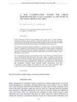
will be placed, as shown in Fig. 1a.
This technique combines three components:
(1) embankment material, (2) a load transfer
platform (LTP), and (3) vertical elements
extending from the LTP to the stiff substratum.
The surface and embankment loads are partially
transferred to the piles by arching that occurs in
the granular material constituting the LTP (Fig.
1b).
The
load
re-distribution
causes
homogenization and the reduction of surface
settlements. Although this technique is widely
used, the mechanisms involved are still poorly
understood.
Soil layers and underlying geosynthetics
are assumed initially to be resting on a firm
foundation. At some point in time, a void of
a certain size opens below the geosynthetic.
Under the weight of soil layers and any
applied loads, geosynthetics will be
deflected. The deflection has two effects,
bending of soil layers and stretching of the
geosynthetics.
NG - S 62 (9/2018)
95
b
a
Fig. 1. Geosynthetic reinforced piled supported embankment (after Eskisar et al., 2013)
The bending of the soil layer generates the
arching effect inside the soil due to the highly
significant difference in stiffness of the piles
relative to the surrounded soft soil. As a result,
the vertical stresses are concentrated in the area
over the piles, simultaneously the stresses over
the soft soil reduce and is smaller than the
average vertical stress of embankment.
The stretching of the geosynthetic mobilizes
a portion of the geosynthetic strength.
Consequently, the geosynthetic acts as a
“tensioned membrane” and can carry a load
applied normally to its surface. As a result of
geosynthetic stretching, the load on the piles
may be increased by the vertical components of
the tension forces in the reinforcement. The
redistribution mechanism of loads in the
embankment depends generally on the geometry
of system, the strength of embankment soil, the
stiffness of piles and support of soft subsoil.
Several methods have proposed and currently
used for estimating the soil arching effect
(e.g.Terzaghi, 1943; Guido et al., 1987; Low et
al., 1994; BS8006, 1995; Russell and Pierpoint,
1997; Hewett and Randolph, 1998; EBGEO,
2004; Kempfert et al., 2004; Van Eekelen et al.,
2013). However, until now there is no analytical
approach which describes precisely this
complex behavior of a system consists of the
embankment – reinforcement – piles – soft
subsoil.
In spite of its limitation, this current study is
an attempt to shed more light on the arching
phenomenon using a mathematical model and
numerical analysis. Simple expressions for the
reduced load caused by arching are proposed. In
96
addition, a design method of geosynthetic
reinforcement has also proposed in this study by
combining arching effect with tensioned
membrane action and frictional resistance
mechanism, thereby providing suitable and
realistic design approach. This method can
estimate the degree of arching in the
embankment and calculate the required
properties of the geosynthetic reinforcement that
is a good match with experimental, numerical
and field observations.
2. THEORETICAL ANALYSIS
The proposed method in this study is a new
analytical model, and a two-step approach is
therefore used. First, the behavior of the soil
layer is analyzed using arching theory. This step
gives the pressure at the base of the soil layer on
the portion of the geosynthetic located above the
soft ground. Second, tensioned membrane
theory is used to establish a relationship
between the pressure on the geosynthetic, the
tension and strain in the geosynthetic, and the
deflection of the geosynthetic. These coupled
effects will be considered in a later section.
2.1. Definition
Three related terms are used to assess the
degree of arching in an embankment. Firstly,
efficacy, E, is the percentage by weight of the
embankment fill carried by the pile caps. The
stress reduction ratio, SRR, is the ratio of the
actual average vertical stress on the soft ground
to the value of overburden stress, γH. The stress
concentration ratio is the ratio of stress on the
pile cap to stress on soft ground. If there is no
arching, efficacy is equal to (Ap/A) x 100%, and
the stress reduction ratio equals to 1.0.
KHOA H C K THU T TH Y L I VÀ MÔI TR
NG - S 62 (9/2018)
Pp
E=
× 100%
A(γH + qo )
Ps
σs
SRR =
=
( A − Ap )(γH + qo ) γH + qo
n=
σp
σs
(1);
(2);
(3)
where Pp is the load on a pile-cap; Ps is the load
on soft-ground area; A is the tributary area of a
pile-cap; Ap is the area of a pile-cap; γ is the
unit weight of the fill; H is the embankment
height; σp is the vertical stress applied on a pilecap; σs is the vertical stress acting soft soil.
H
Uniform surcharge, q o
a
s/2
Pile cap
Soft subsoil
Pile cap
s
Pile
As/2
Pile
s
a
s'
a
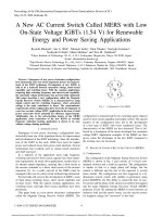
Fig.2. Stress distribution in an area of influence
KHOA H C K THU T TH Y L I VÀ MÔI TR
Overburden pressure
Granular soil maretial
o v e rb u rd e n h e ig h t H
Taking into account a model of square
pattern as shown in Fig. 2. The total pile cap
area per an area of influence is Ap=a2 and the
remaining area covered by soft ground is (As =
s2-a2). The following relationships are easily
established:
s2
E = 1− 2
SRR
(4);
s − a2
E.(γH + qo ) s 2
(5);
σ p ==
a2
σp
E s2 − a2
E s2
(6)
n=
=
=
.
σ s 1 − E a2
SRR a 2
2.2. Step 1. Prediction method of soil
arching
As a starting point, the shape of the stable
physical arch is presumed to be a circular curve,
as depicted in Fig. 3. Let θ be the inclination,
concerning the horizontal of the tangent line
through each end of the arch spanning width s’
of the inclusion.
Clear spacing or effective width s'
curved arch
settlement plate
initial surface
settlement d
Reaction of ground
Pile
Fig.3. Assumed-shape of the stable
physical arch
For a circular arch with an inclination angle θ
at the sides with respect to the horizontal, this
results in (7) and (8), (after Miki, 1997).
2
2
po = Vs .γ /[(s'+a ) − πd c / 4]
(7)
NG - S 62 (9/2018)
97
2
3
Vs = 0.5s' (s'+ d c ) tan θ − π tan θ [( s'+ d c ) 3 − a 3 ] / 24 + (4 − π ) 2 − 1 (s'+ d c ) tan θ / 24
(
θ = 900 – φ
(8b)
SRR = Ps / γVt = αγVs / γVt = αVs / Vt
(9)
where Vs is the embankment volume acting
on the soft ground in-between; Vt is the total
volume of embankment; po is the pressure
acting on the soft ground in-between; α is the
arching shape dimension ratio; a is the width of
pile-cap; s’is the clear spacing and equal (s-a);
SRR is the stress reduction ratio.
The arching shape ratio α based on the basis
of empirical model and numerical results is:
(10)
α = m H / s +0.5 × H 0.5 × 1.1k
)
(8a)
m = 1.3+0.05(H/s)
(11)
k = Es (1 +ν p )(1 − 2ν p ) / Ep (1 +ν s )(1 − 2ν s ) (12)
where H is the embankment height, s is the
center to center pile spacing, k is called modular
ratio between the pile and soft ground. Ep is the
elastic modulus of the pile, νp is the Poisson's ratio
of the pile material, Es is the elastic modulus of
soft soil, νs is Poisson's ratio of soft soil.
Substitute (8), (10) back into (7) gives the
vertical stress acting on the soft ground:
m H / s +0.5 × H 0.5 × 1.1k .(γ + q / H ) π
0
σs =
× (s x − d e )(s y − d c )tan θ (5d c + 4 s x )
2
2
96
2( s − πd / 4)
c
sx + sy
sx × s y sx + s y − 2d c
+ (4 − π )
tan θ +
4
4
12
(
2 − 1 tan θ
)
(13)
For a square arrangement of piles with sx = sy = s, the Eq. (13) becomes:
σ =
s
2
π
s
s s − dc
2
× (s − d c ) tan θ (5d c + 4 s ) + (4 − π )
tan θ + 2 − 1 tan θ
96
6
2 2
2 ( s 2 − πd 2 / 4 )
c
α (γ + q / H )
(
0
)
(14)
where sx, sy - pile center-to-center spacing in directions of x and y; dc – diameter of pile cap
d c = d for round pile cap; d c = 2a / π for square pile cap
(15)
2.3. Step 2. Analysis method of
geosynthetic reinforcement
In the second step, the vertical stress, σs, is
applied to the geosynthetic reinforcement as an
external load. When one or more layers of
geosynthetic are placed at the top of pile caps, a
possible upwards counter-pressure, σup, from the
partially compressed upper zone of soft subsoil
between piles is assumed, which reduces the
tension in reinforcement, as shown in Fig. 4. Eq.
(16) had to be developed to reflect this
interaction.
Stress applies on top of
reinforcement s
Uniform surcharge, qo
Embankment
T
r
T
Pile cap
T
Pile cap
Reaction
up
Pile cap
T
t
Pile cap
Pile
geosynthetic
s
a
s'
Fig. 4. Idealized stress distribution
98
Pile
a
s
Fig. 5. Assumed-shape of geosynthetic
KHOA H C K THU T TH Y L I VÀ MÔI TR
NG - S 62 (9/2018)
The influence of bearing effect of the soft
subsoil between piles is taken into account by
using a modulus of subgrade reaction.
σGR = σ s − σup = σ s − tEs / D
(16)
where σGR is the stress induces the tension in
geosynthetic; t is the deflection of geosynthetic
or differential settlement; Es is the average
elastic modulus of multiple soft soil layers; D is
the thickness of soft soil layer.
By considering a deformed length of
geosynthetic, ∆ld, the tensile force in the
geosynthetic reinforcement is a function of
strain, and is approximately equal to:
2
∆l
8 t
(17)
ε a = d ≈
s'
3 s'
Assuming the strain is uniform, the tension in
the geosynthetic is a function of the amount of
strain in the geosynthetic. The tension in the
geosynthetic is determined as follows:
T = σ GR Ωs' = [σ s − tE s / D ].Ωs' (18)
In which, s’ = span design for tensioned
membrane (s’=s–a), Ω = dimensionless factor
from tensioned membrane theory. The
dimensionless factor Ω is defined by Giroud et
al. (1990)
1 2t s'
Ω= +
(19)
4 s ' 2t
Substitute Eq. (19) into Eq. (18), the
resulting of the tension in the geosynthetic is
1
2t s '
given: T = [σ s − tEs / D ]. + s' (20)
4
s ' 2t
On the other hand, under the influence of fill
weight, the embankment between pile caps has
a tendency to move downward, due to the
presence of soft foundation soil. This movement
is partially restrained by shear resistance, τ,
which reduces the pressure acting on the
geosynthetic but increase the load transferred
onto the column caps (Han and Garb, 2002).
The shear resistance is a result of skin
friction at the top and bottom of soilgeosynthetic interfaces. The expression of shear
resistance is
τ = ∑ σ n tan δ i =(σ s λ p tan φ p + (tE s / D )λs tan φs + λc {c p + c s })
(21)
i =1
where σn is the normal stress on the interface;
δi is the interface friction angle, ϕp is the
effective friction angle of the platform soil
layer; ϕs is the effective friction angle of the
subsoil; cp is the adhesion value of platform soil
layer; ci is the adhesion value of soils; λp and λc
are interaction coefficients between the
reinforcement material and the proposed soils.
Due to the effect of underground water, value λc
is relatively small and varies from 0.1 to 0.2.
8t 2 J GR s'
T=
+ (σ s λ p tan φ p + (tEs / D)λs tan φs
3s' 2
4
2.4. Design solutions of a piled
embankment reinforced geosynthetic
Combining (20) and (234) implies a relevant
third-order equation as follows:
α 1t 3 + α 2 t 2 + α 3 t + α 4 = 0
(24)
in which,
KHOA H C K THU T TH Y L I VÀ MÔI TR
The total tensile force in the geosynthetic is
calculated by the following expression:
s '/ 2
s '/ 2
J ∆l
(22)
∫0 Tdx = GR2 d + ∫0 τxdx
where JGR is the tensile stiffness of the
geosynthetic(kN/m); T is a maximum tensile
force.
By integrating and imposing (17), (21) into
(22), this leads to:
+ λc {c p + cs })
(23)
α 1 = 12 E s s ' 2 +64 DJ GR ;
α 2 = 6 E s s ' 3 λ s tan φs − 12σ s Ds ' 2 ;
α3 = 6σ s Ds'3 λp tanφp + 3Es s'4 +6D(c p + cs )λc s'3 ;
α 4 = −3σ s Ds' 4
The solution of (24) gives the deflection of
geosynthetic, t. Then, the remaining design
NG - S 62 (9/2018)
99
parameters can be derived. The maximum
tensile force of geosynthetic is determined by
(20), and the maximum strain of geosynthetic is
easily calculated by relationship ε = T/JGR.
The other parameters can be derived by
using (4), (5), (6).
3. DISCRETE ELEMENT MODELLING
OF PROBLEMS
In this study, a three-dimensional software
(SDEC) based on the discrete element method
has been used for analysis (Villard et al., 2004).
The algorithm of calculation used consists in
successively alternating the application of
Newton's second law.
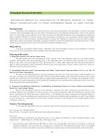
Geometry: Because of the symmetric
condition, only a quarter mesh was modeled to
reduce time-consuming calculation in this study.
An illustrative example of piled embankment
reinforced geosynthetic is shown in Fig. 6. For a
control case, pile spacing installed is 3m; the
width of pile-cap equals 0.6m.
Soft ground: The soft subsoil is modeled like
as springs by using a Winkler's Spring Model.
The reaction of the subgrade soil is taken into
account by using a subgrade reaction
coefficient.
Geosynthetic: The geosynthetic sheet in this
study is a non-woven geosynthetic, which
modeled by 16 directions of fibers. These
elements allow describing the tensile and
Fig. 6. Geometry of problem by SDEC
Fig. 7. Particle shape of the embankment
4. ANALYSIS OF RESULTS AND
DISCUSSION
In order to investigate the validity of the
100
membrane behavior of the sheet well. The
micromechanical parameters consist of a normal
& tangential, rigidity of contact, a tensile
stiffness of the geosynthetic, an interactive
friction angle geosynthetic/soil
Embankment material: The embankment is
modeled by discrete element (8000 particles per
m3). The particles shape is given in Fig.
7.
The vertical interfaces between pile-soilgeosynthetic were modeled. The mechanical
properties of interfaces have the similarity to
mechanical properties of embankment clusters.
Pile element: The pile element is modeled as
the embedded pile with a very large stiffness, in
which piles are considered as beam elements, is
used to define the properties of pile group.
Interface behavior: Specific interaction laws
are used to characterize the interface behavior
between the soil particles and the sheet
elements. The main contact parameters are the
normal rigidity, the tangential rigidity, and the
friction angle. In order to rather than the
absence of relative roughness between the sheet
elements and the soil particles, the microscopic
friction angle of contact between exactly to the
macroscopic friction angle given by the model.
Boundary
condition:
The
boundary
conditions include four frictionless vertical rigid
walls to fix the horizontal displacement because
of the symmetric condition.
presented method, the results are compared to
the numerical analysis by DEM. One of the
well-known design procedures currently is
KHOA H C K THU T TH Y L I VÀ MÔI TR
NG - S 62 (9/2018)
EBGEO (2004) that also used for comparison in
this section. The summary of the embankment
geometry and design parameters used in this
study case as follows:
Pile: cap width is 0.6m; pile spacing is 3m;
Poisson ratio is 0.25; elastic modulus is 1.5x10⁶
kN/m2. Embankment fill: Height is 0.75-3m;
unit weight is 20kN/m3; peak friction angle is
400. Platform fill (gravel): Friction angle is 400.
Soft ground: Thickness is 10m; elastic modulus
is 1800kN/m2; friction angle is 100; cohesion is
12kN/m2; Poisson ratio is 0.33. Geosynthetic:
tensile stiffness is 3000kN/m; λp equals to 1.0,
λs equals to 0.62; λc equals to 0.1. No surcharge
load. Piles are arranged in a square pattern.
4.1. Load transfer mechanis
Fig. 8. Stress distribution from numerical modeling (a - 2D and b, c – surface of 3D)
Due to the inclusion of geosynthetic, the
vertical stress distribution above and below the
geosynthetic is different as shown in Fig. 8. The
stress above the geosynthetic is mainly induced
by soil arching while the stress below the
geosynthetic is influenced not only by soil
arching but also by the component of tension
from the geosynthetic. As compared with the
vertical stress magnitude for an unreinforced
case, the vertical stress above the geosynthetic
is less than that for the unreinforced case within
the range of the pile cap. The benefit of reduced
vertical stress above the geosynthetic and the
pile is realized through minimizing the
possibility of soil yielding or pile punching into
the embankment (Fig. 8b). Meanwhile, the
benefit of increased vertical stress below the
geosynthetic is that membrane effect increased
KHOA H C K THU T TH Y L I VÀ MÔI TR
and more load transfer onto the piles (Fig. 8c)
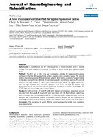
4.2. Comparison of efficacy
A comparison of the design methods with
numerical analysis for different height of
embankment is shown in Fig. 9. According to
the results, the proposed method produces an
excellent agreement with the numerical results.
Whereas, the EBGEO method significantly
underpredict the efficacy of pile, which yields
an over-conservative result.
The analysis also shows that the efficacy
increases with an increase in the height of the
embankment. With the increase in the height of
the embankment, more shear resistance
accumulates for enhancing the development of
soil arching. It can be seen that the efficacy
approaches a limiting value when the height of
the embankment is increased.
NG - S 62 (9/2018)
101
140
Differential settlement (mm)
Efficacy of Pile (%)
50
40
30
20
Proposed Method
EBGEO Method
Numerical Method
10
80
60
40
Proposed Method
Numerical Method
0
0.5
1
1.5
2
2.5
Embankment height (m)
0.5
3
1
1.5
2
2.5
3
Embankment height (m)
Fig. 9. Efficacy with fill height
Fig. 10. Differential settlement with a fill height
4.3. Comparison of differential settlement
The differential settlement defined as the
settlement difference between the center of
the pile and the midpoint of the pile spacing.
As presented in Fig. 10, the results show that
the differential settlement increases with the
height of the embankment fill. Such increase
is estimated to be 155% when the
embankment height is increased from 0.75m
to 3m. It can be also seen that the results
obtained from the proposed method agree well
with the numerical results, only 2-6% in
errors. This can be explained by the inclusion
of membrane effect of geosynthetic into the
proposed method. The EBGEO design
procedures do not give the equation for
prediction of differential settlement, hence it
is not presented here.
4.4. Comparison of strain and tension in
geosynthetic
2
60
1.8
50
Strain of geosynthetic (%)
Tension in geosynthetic (kN/m)
100
20
0
40
30
20
Proposed Method
10
1.6
1.4
1.2
1
0.8
0.6
Proposed Method
0.4
EBGEO Method
EBGEO Method
0.2
Numerical Method
0
Numerical method
0
0.5
1
1.5
2
2.5
3
Embankment height (m)
Fig. 11. Maximum tensile force with fill height
For the design purposes, the maximum strain
and tension in geosynthetic are of more interest
to geotechnical engineers, which is further
investigated herein. As shown in Fig. 11, the
maximum tension in the geosynthetic increases
102
120
0.5
1
1.5
2
Embankment height (m)
2.5
3
Fig. 12. Maximum strain with fill height
with the height of embankment fill. In addition,
the proposed method gives a reasonable match
to the numerical results while the EBGEO
results are over-estimation highly compared to
the numerical results. Similarly, the good match
KHOA H C K THU T TH Y L I VÀ MÔI TR
NG - S 62 (9/2018)
between the proposed method and numerical
method is also seen in the term of a maximum
strain of geosynthetic, which yields a suitable
approach of the proposed method, as shown in
Fig. 12. Therefore, the maximum value of
geosynthetic strain obtained from the proposed
method can be a good value to be used in
design, which yields more economical and
effective.
5. CONCLUSIONS
This study presents a proposed method for
the design of geosynthetic reinforced pile
supported embankment. The developed design
method was established by combining tensioned
membrane theory of geosynthetic materials with
arching soil theory in the granular embankment,
which allows considering the interaction
behavior
between
pile-geosynthetic-soils,
thereby providing a more suitable design
method in practice.
The proposed method provides a simple
equation to perform design analyses for a range
of possible field situations. In addition, the
three-dimensional approach with using a stress
reduction ratio in the proposed method
presented here. Therefore, the proposed method
provides a useful tool to consider the role of
geosynthetic, effect of soft soil and properties of
fill materials, which have generally neglected in
the currently available methods.
The results of comparison showed that the
results obtained from the present method agree
well with numerical results, and generally better
than the one of EBGEO in this study.
The results indicate that the efficacy
increases with an increase in the height of
embankment, and approaches to a limiting value
at a large value of embankment height. It is
found that geosynthetic enhances the load
transfer from the soil to the piles by tensioned
membrane effect.
The study results also suggest that the vertical
stress concentrated significantly at the edge of
the pile cap. The vertical stress above the
geosynthetic is less than that for the unreinforced
case within the range of the pile cap.
REFERENCES
BS 8006, 2010. Code of Practice for Strengthened/Reinforced Soils and Other Fills. British
Standard Institution, UK.
EBGEO, 2010. Emfehlungen für den Entwurf und die Berechnung von Erdkorpern mit
Bewehrungen aus Geokunststoffen – EBGEO, 2. German Geotechnical Society, Auflage ISBN
978-3-433-02950-3.
Guido, V.A, Kneuppel, J.D., Sweeney, M.A., 1987. Plate loading tests on geogrid reinforced earth
slabs (New Orleans). Proc. Geosynthetics 87, 216–225.
Giroud, J. P., Bonaparte, R., Beech, J. F., & Gross, B. A. (1990). Design of soil layer-geosynthetic
systems overlying voids. Geotextiles and Geomembranes, 9(1), 11–50.
Han, J., Gabr, M.A., 2002. Numerical analysis of geosynthetic-reinforced and pile-supported earth
platforms over soft soil. J. Geotech. Geoenviron. Eng. 128 (1), 44–53.
Han, J., & Alzamora, D. E. (Eds.). (2011, February). Geo-Frontiers 2011: Advances in
Geotechnical Engineering. American Society of Civil Engineers.
Hewlett, W.J., Randolph, M.F., 1988. Analysis of piled embankments. Ground Eng. 21 (3), 12–18.
Jenck, O., Dias, D., & Kastner, R. (2005). Soft ground improvement by vertical rigid piles twodimensional physical modelling and comparision with current design methods. Soils and
Foundations, 45(6), 15-30.
Johnes, C. J. F. P., Lawson, C. R., & Ayres, D. J. (1990). Geotextile reinforced piled
embankment. Geotextile, Geomembranes and Related Products, 155-160.
KHOA H C K THU T TH Y L I VÀ MÔI TR
NG - S 62 (9/2018)
103
Low, B. K., Tang, S. K., & Choa, V. (1994). Arching in piled embankments. Journal of
Geotechnical Engineering, 120(11), 1917-1938.
Miki, H. (1997). Design of deep mixing method of stabilization with low improvement ratio.
In Proceedings of the first seminar on ground improvement in highways, Bangkok, Thailand,
August (pp. 197-204).
Russell, D., & Pierpoint, N. (1997). An assessment of design methods for piled
embankments. Ground Engineering, 30(10).
Sloan, J. (2011). Column-supported embankments: full-scale tests and design recommendations.
Terzaghi, K., 1943. Theoretical Soil Mechanics. Wiley, New York.
Villard, P., & Chareyre, B. (2004). Design methods for geosynthetic anchor trenches on the basis of
true scale experiments and discrete element modelling. Canadian Geotechnical Journal, 41(6),
1193-1205.
Van Eekelen, S. J. M., Bezuijen, A., & Van Tol, A. F. (2013). An analytical model for arching in
piled embankments. Geotextiles and Geomembranes, 39, 78-102.
Abstract:
MỘT PHƯƠNG PHÁP MỚI CHO VIỆC THIẾT KẾ NỀN ĐẮP
ĐƯỢC XÂY DỰNG TRÊN HỆ CỌC KẾT HỢP VẬT LIỆU GIA CƯỜNG
Kỹ thuật gia cường đất với cọc đã được chứng minh là một giải pháp thú vị bởi khả năng đảm bảo
sự ổn định của nền đắp. Một vài phương pháp lý thuyết dựa trên các mô hình đơn giản hóa đã được
đề xuất nhưng kết quả từ các phương pháp này thường cao hơn đáng kể và quá an toàn, đưa đến
thiết kế không đạt hiệu quả kinh tế tối ưu. Nghiên cứu này trình bày một phương pháp phân tích
mới cho việc thiết kế nền đắp trên hệ cọc kết hợp vật liệu gia cường, dựa trên sự kết hợp của hiệu
ứng vòm, hiệu ứng màng căng và cơ chế tương tác sức kháng cắt. Phương pháp trình bày có khả
năng để mô tả ứng xử và những tương tác phức tạp giữa vật liệu gia cường-đất-cọc, và do đó cung
cấp một phương pháp thiết kế nhiều thích hợp cho các kỹ sư. Thêm vào đó, mô hình số dựa trên
phương pháp phần tử rời rạc (DEM) với các ngôn ngữ mã mới nhất cũng đã được sử dụng để
nghiên cứu độ tin cậy của phương pháp đề xuất. Các kết quả nghiên cứu hướng đến việc cung cấp
một số chỉ dẫn cho các nhà thiết kế, và làm sáng tỏ một vài cơ chế tương tác trong nền đắp có gia
cường vật liệu địa kỹ thuật.
Từ khóa: Nền đắp, cọc, vật liệu gia cường, phương pháp đề xuất, thiết kế, phân tích số,
Ngày nhận bài:
10/5/2018
Ngày chấp nhận đăng: 07/8/2018
104
KHOA H C K THU T TH Y L I VÀ MÔI TR
NG - S 62 (9/2018)