Lecture Mechanics of materials (Third edition) - Chapter 4: Pure bending
Bạn đang xem bản rút gọn của tài liệu. Xem và tải ngay bản đầy đủ của tài liệu tại đây (4.4 MB, 42 trang )
Third Edition
CHAPTER
MECHANICS OF
MATERIALS
Ferdinand P. Beer
E. Russell Johnston, Jr.
John T. DeWolf
Pure Bending
Lecture Notes:
J. Walt Oler
Texas Tech University
© 2002 The McGraw-Hill Companies, Inc. All rights reserved.
Third
Edition
MECHANICS OF MATERIALS
Beer • Johnston • DeWolf
Pure Bending
Pure Bending
Other Loading Types
Symmetric Member in Pure Bending
Bending Deformations
Strain Due to Bending
Beam Section Properties
Properties of American Standard Shapes
Deformations in a Transverse Cross Section
Sample Problem 4.2
Bending of Members Made of Several
Materials
Example 4.03
Reinforced Concrete Beams
Sample Problem 4.4
Stress Concentrations
Plastic Deformations
Members Made of an Elastoplastic Material
© 2002 The McGraw-Hill Companies, Inc. All rights reserved.
Example 4.03
Reinforced Concrete Beams
Sample Problem 4.4
Stress Concentrations
Plastic Deformations
Members Made of an Elastoplastic Material
Plastic Deformations of Members With a Single
Plane of S...
Residual Stresses
Example 4.05, 4.06
Eccentric Axial Loading in a Plane of Symmetry
Example 4.07
Sample Problem 4.8
Unsymmetric Bending
Example 4.08
General Case of Eccentric Axial Loading
4-2
Third
Edition
MECHANICS OF MATERIALS
Beer • Johnston • DeWolf
Pure Bending
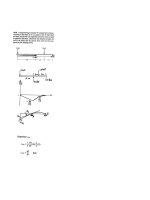
Pure Bending: Prismatic members
subjected to equal and opposite couples
acting in the same longitudinal plane
© 2002 The McGraw-Hill Companies, Inc. All rights reserved.
4-3
Third
Edition
MECHANICS OF MATERIALS
Beer • Johnston • DeWolf
Other Loading Types
• Eccentric Loading: Axial loading which
does not pass through section centroid
produces internal forces equivalent to an
axial force and a couple
• Transverse Loading: Concentrated or
distributed transverse load produces
internal forces equivalent to a shear
force and a couple
• Principle of Superposition: The normal
stress due to pure bending may be
combined with the normal stress due to
axial loading and shear stress due to
shear loading to find the complete state
of stress.
© 2002 The McGraw-Hill Companies, Inc. All rights reserved.
4-4
Third
Edition
MECHANICS OF MATERIALS
Beer • Johnston • DeWolf
Symmetric Member in Pure Bending
• Internal forces in any cross section are equivalent
to a couple. The moment of the couple is the
section bending moment.
• From statics, a couple M consists of two equal
and opposite forces.
• The sum of the components of the forces in any
direction is zero.
• The moment is the same about any axis
perpendicular to the plane of the couple and
zero about any axis contained in the plane.
• These requirements may be applied to the sums
of the components and moments of the statically
indeterminate elementary internal forces.
Fx = ∫ σ x dA = 0
M y = ∫ zσ x dA = 0
M z = ∫ − yσ x dA = M
© 2002 The McGraw-Hill Companies, Inc. All rights reserved.
4-5
Third
Edition
MECHANICS OF MATERIALS
Beer • Johnston • DeWolf
Bending Deformations
Beam with a plane of symmetry in pure
bending:
• member remains symmetric
• bends uniformly to form a circular arc
• cross-sectional plane passes through arc center
and remains planar
• length of top decreases and length of bottom
increases
• a neutral surface must exist that is parallel to the
upper and lower surfaces and for which the length
does not change
• stresses and strains are negative (compressive)
above the neutral plane and positive (tension)
below it
© 2002 The McGraw-Hill Companies, Inc. All rights reserved.
4-6
Third
Edition
MECHANICS OF MATERIALS
Beer • Johnston • DeWolf
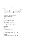
Strain Due to Bending
Consider a beam segment of length L.
After deformation, the length of the neutral
surface remains L. At other sections,
L′ = ( ρ − y )θ
δ = L − L′ = ( ρ − y )θ − ρθ = − yθ
εx =
εm =
δ
=−
L
c
ρ
yθ
ρθ
or
=−
ρ=
y
ρ
(strain varies linearly)
c
εm
y
c
ε x = − εm
© 2002 The McGraw-Hill Companies, Inc. All rights reserved.
4-7
Third
Edition
MECHANICS OF MATERIALS
Beer • Johnston • DeWolf
Stress Due to Bending
• For a linearly elastic material,
y
c
σ x = Eε x = − Eε m
y
= − σ m (stress varies linearly)
c
• For static equilibrium,
y
Fx = 0 = ∫ σ x dA = ∫ − σ m dA
c
σ
0 = − m ∫ y dA
c
First moment with respect to neutral
plane is zero. Therefore, the neutral
surface must pass through the
section centroid.
• For static equilibrium,
⎛ y
⎞
M = ∫ − yσ x dA = ∫ − y⎜ − σ m ⎟ dA
⎝ c
⎠
σ
σ I
M = m ∫ y 2 dA = m
c
c
σm =
Mc M
=
I
S
y
Substituting σ x = − σ m
c
σx = −
© 2002 The McGraw-Hill Companies, Inc. All rights reserved.
My
I
4-8
Third
Edition
MECHANICS OF MATERIALS
Beer • Johnston • DeWolf
Beam Section Properties
• The maximum normal stress due to bending,
Mc M
=
I
S
I = section moment of inertia
I
S = = section modulus
c
σm =
A beam section with a larger section modulus
will have a lower maximum stress
• Consider a rectangular beam cross section,
3
1
I 12 bh
S= =
= 16 bh3 = 16 Ah
c
h2
Between two beams with the same cross
sectional area, the beam with the greater depth
will be more effective in resisting bending.
• Structural steel beams are designed to have a
large section modulus.
© 2002 The McGraw-Hill Companies, Inc. All rights reserved.
4-9
Third
Edition
MECHANICS OF MATERIALS
Beer • Johnston • DeWolf
Properties of American Standard Shapes
© 2002 The McGraw-Hill Companies, Inc. All rights reserved.
4 - 10
Third
Edition
MECHANICS OF MATERIALS
Beer • Johnston • DeWolf
Deformations in a Transverse Cross Section
• Deformation due to bending moment M is
quantified by the curvature of the neutral surface
ε
σ
1 Mc
= m = m =
c
Ec Ec I
ρ
M
=
EI
1
• Although cross sectional planes remain planar
when subjected to bending moments, in-plane
deformations are nonzero,
ε y = −νε x =
νy
ρ
ε z = −νε x =
νy
ρ
• Expansion above the neutral surface and
contraction below it cause an in-plane curvature,
1 ν
= = anticlastic curvature
ρ′ ρ
© 2002 The McGraw-Hill Companies, Inc. All rights reserved.
4 - 11
Third
Edition
MECHANICS OF MATERIALS
Beer • Johnston • DeWolf
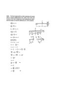
Sample Problem 4.2
SOLUTION:
• Based on the cross section geometry,
calculate the location of the section
centroid and moment of inertia.
Y =
∑ yA
∑A
(
I x′ = ∑ I + A d 2
)
• Apply the elastic flexural formula to
find the maximum tensile and
compressive stresses.
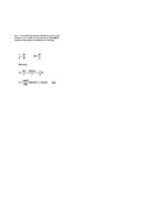
σm =
A cast-iron machine part is acted upon
by a 3 kN-m couple. Knowing E = 165
GPa and neglecting the effects of
fillets, determine (a) the maximum
tensile and compressive stresses, (b)
the radius of curvature.
© 2002 The McGraw-Hill Companies, Inc. All rights reserved.
Mc
I
• Calculate the curvature
1
ρ
=
M
EI
4 - 12
Third
Edition
MECHANICS OF MATERIALS
Beer • Johnston • DeWolf
Sample Problem 4.2
SOLUTION:
Based on the cross section geometry, calculate
the location of the section centroid and
moment of inertia.
Area, mm 2
y , mm
yA, mm3
1 20 × 90 = 1800
50
90 × 103
2 40 × 30 = 1200
20
24 × 103
∑ A = 3000
∑ yA = 114 × 10
3
3
∑ yA 114 × 10
Y =
=
= 38 mm
3000
∑A
(
) (
1 bh3 + A d 2
I x′ = ∑ I + A d 2 = ∑ 12
(
)(
)
1 90 × 203 + 1800 × 12 2 + 1 30 × 403 + 1200 × 182
= 12
12
I = 868 × 103 mm = 868 × 10-9 m 4
© 2002 The McGraw-Hill Companies, Inc. All rights reserved.
4 - 13
)
Third
Edition
MECHANICS OF MATERIALS
Beer • Johnston • DeWolf
Sample Problem 4.2
• Apply the elastic flexural formula to find the
maximum tensile and compressive stresses.
Mc
I
M c A 3 kN ⋅ m × 0.022 m
=
σA =
I
868 × 10−9 mm 4
M cB
3 kN ⋅ m × 0.038 m
=−
σB = −
I
868 × 10−9 mm 4
σm =
σ A = +76.0 MPa
σ B = −131.3 MPa
• Calculate the curvature
1
ρ
=
=
M
EI
3 kN ⋅ m
(165 GPa )(868 ×10-9 m 4 )
© 2002 The McGraw-Hill Companies, Inc. All rights reserved.
1
= 20.95 × 10⁻³ m -1
ρ
ρ = 47.7 m
4 - 14
Third
Edition
MECHANICS OF MATERIALS
Beer • Johnston • DeWolf
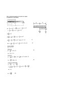
Bending of Members Made of Several Materials
• Consider a composite beam formed from
two materials with E1 and E2.
• Normal strain varies linearly.
εx = −
y
ρ
• Piecewise linear normal stress variation.
σ 1 = E1ε x = −
E1 y
ρ
σ 2 = E2ε x = −
E2 y
ρ
Neutral axis does not pass through
section centroid of composite section.
• Elemental forces on the section are
Ey
E y
dF1 = σ 1dA = − 1 dA dF2 = σ 2 dA = − 2 dA
ρ
σx = −
My
I
σ1 = σ x
ρ
• Define a transformed section such that
σ 2 = nσ x
© 2002 The McGraw-Hill Companies, Inc. All rights reserved.
dF2 = −
(nE1 ) y dA = − E1 y (n dA)
ρ
ρ
E
n= 2
E1
4 - 15
Third
Edition
MECHANICS OF MATERIALS
Beer • Johnston • DeWolf
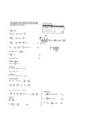
Example 4.03
SOLUTION:
• Transform the bar to an equivalent cross
section made entirely of brass
• Evaluate the cross sectional properties of
the transformed section
• Calculate the maximum stress in the
transformed section. This is the correct
maximum stress for the brass pieces of
the bar.
Bar is made from bonded pieces of
steel (Es = 29x106 psi) and brass
(Eb = 15x106 psi). Determine the
maximum stress in the steel and
brass when a moment of 40 kip*in
is applied.
• Determine the maximum stress in the
steel portion of the bar by multiplying
the maximum stress for the transformed
section by the ratio of the moduli of
elasticity.
© 2002 The McGraw-Hill Companies, Inc. All rights reserved.
4 - 16
Third
Edition
MECHANICS OF MATERIALS
Beer • Johnston • DeWolf
Example 4.03
SOLUTION:
• Transform the bar to an equivalent cross section
made entirely of brass.
Es 29 × 106 psi
n=
=
= 1.933
Eb 15 × 106 psi
bT = 0.4 in + 1.933 × 0.75 in + 0.4 in = 2.25 in
• Evaluate the transformed cross sectional properties
1 b h3 = 1 (2.25 in.)(3 in )3
I = 12
T
12
= 5.063 in 4
• Calculate the maximum stresses
σm =
Mc (40 kip ⋅ in )(1.5 in )
=
= 11.85 ksi
4
I
5.063 in
(σ b )max = σ m
(σ s )max = nσ m = 1.933 ×11.85 ksi
© 2002 The McGraw-Hill Companies, Inc. All rights reserved.
(σ b )max = 11.85 ksi
(σ s )max = 22.9 ksi
4 - 17
Third
Edition
MECHANICS OF MATERIALS
Beer • Johnston • DeWolf
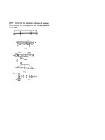
Reinforced Concrete Beams
• Concrete beams subjected to bending moments are
reinforced by steel rods.
• The steel rods carry the entire tensile load below
the neutral surface. The upper part of the
concrete beam carries the compressive load.
• In the transformed section, the cross sectional area
of the steel, As, is replaced by the equivalent area
nAs where n = Es/Ec.
• To determine the location of the neutral axis,
(bx ) x − n As (d − x ) = 0
2
1 b x2
2
+ n As x − n As d = 0
• The normal stress in the concrete and steel
σx = −
My
I
σc = σ x
© 2002 The McGraw-Hill Companies, Inc. All rights reserved.
σ s = nσ x
4 - 18
Third
Edition
MECHANICS OF MATERIALS
Beer • Johnston • DeWolf
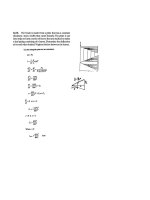
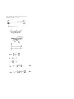
Sample Problem 4.4
SOLUTION:
• Transform to a section made entirely
of concrete.
• Evaluate geometric properties of
transformed section.
• Calculate the maximum stresses
in the concrete and steel.
A concrete floor slab is reinforced with
5/8-in-diameter steel rods. The modulus
of elasticity is 29x106psi for steel and
3.6x10⁶psi for concrete. With an applied
bending moment of 40 kip*in for 1-ft
width of the slab, determine the maximum
stress in the concrete and steel.
© 2002 The McGraw-Hill Companies, Inc. All rights reserved.
4 - 19
Third
Edition
MECHANICS OF MATERIALS
Beer • Johnston • DeWolf
Sample Problem 4.4
SOLUTION:
• Transform to a section made entirely of concrete.
Es 29 × 106 psi
=
= 8.06
n=
Ec 3.6 × 10⁶ psi
( )
2
nAs = 8.06 × 2⎡π4 85 in ⎤ = 4.95 in 2
⎢⎣
⎥⎦
• Evaluate the geometric properties of the
transformed section.
⎛ x⎞
12 x⎜ ⎟ − 4.95(4 − x ) = 0
⎝ 2⎠
(
x = 1.450 in
)
I = 13 (12 in )(1.45 in )3 + 4.95 in 2 (2.55 in )2 = 44.4 in 4
• Calculate the maximum stresses.
Mc1 40 kip ⋅ in × 1.45 in
=
I
44.4 in 4
Mc
40 kip ⋅ in × 2.55 in
σ s = n 2 = 8.06
I
44.4 in 4
σc =
© 2002 The McGraw-Hill Companies, Inc. All rights reserved.
σ c = 1.306 ksi
σ s = 18.52 ksi
4 - 20
Third
Edition
MECHANICS OF MATERIALS
Beer • Johnston • DeWolf
Stress Concentrations
Stress concentrations may occur:
• in the vicinity of points where the
loads are applied
σm = K
Mc
I
• in the vicinity of abrupt changes
in cross section
© 2002 The McGraw-Hill Companies, Inc. All rights reserved.
4 - 21
Third
Edition
MECHANICS OF MATERIALS
Beer • Johnston • DeWolf
Plastic Deformations
• For any member subjected to pure bending
y
c
ε x = − εm
strain varies linearly across the section
• If the member is made of a linearly elastic material,
the neutral axis passes through the section centroid
and
σx = −
My
I
• For a material with a nonlinear stress-strain curve,
the neutral axis location is found by satisfying
Fx = ∫ σ x dA = 0
M = ∫ − yσ x dA
• For a member with vertical and horizontal planes of
symmetry and a material with the same tensile and
compressive stress-strain relationship, the neutral
axis is located at the section centroid and the stressstrain relationship may be used to map the strain
distribution from the stress distribution.
© 2002 The McGraw-Hill Companies, Inc. All rights reserved.
4 - 22
Third
Edition
MECHANICS OF MATERIALS
Beer • Johnston • DeWolf
Plastic Deformations
• When the maximum stress is equal to the ultimate
strength of the material, failure occurs and the
corresponding moment MU is referred to as the
ultimate bending moment.
• The modulus of rupture in bending, RB, is found
from an experimentally determined value of MU
and a fictitious linear stress distribution.
RB =
MU c
I
• RB may be used to determine MU of any member
made of the same material and with the same
cross sectional shape but different dimensions.
© 2002 The McGraw-Hill Companies, Inc. All rights reserved.
4 - 23
Third
Edition
MECHANICS OF MATERIALS
Beer • Johnston • DeWolf
Members Made of an Elastoplastic Material
• Rectangular beam made of an elastoplastic material
Mc
I
σ x ≤ σY
σm =
σ m = σY
I
M Y = σ Y = maximum elastic moment
c
• If the moment is increased beyond the maximum
elastic moment, plastic zones develop around an
elastic core.
M =
⎞
⎟
c ⎟⎠
2
⎛
3 M ⎜1 − 1 yY
2 Y⎜
3 2
⎝
yY = elastic core half - thickness
• In the limit as the moment is increased further, the
elastic core thickness goes to zero, corresponding to a
fully plastic deformation.
M p = 32 M Y = plastic moment
Mp
= shape factor (depends only on cross section shape)
k=
MY
© 2002 The McGraw-Hill Companies, Inc. All rights reserved.
4 - 24
Third
Edition
MECHANICS OF MATERIALS
Beer • Johnston • DeWolf
Plastic Deformations of Members With a
Single Plane of Symmetry
• Fully plastic deformation of a beam with only a
vertical plane of symmetry.
• The neutral axis cannot be assumed to pass
through the section centroid.
• Resultants R1 and R2 of the elementary
compressive and tensile forces form a couple.
R1 = R2
A1σ Y = A2σ Y
The neutral axis divides the section into equal
areas.
• The plastic moment for the member,
(
)
M p = 12 Aσ Y d
© 2002 The McGraw-Hill Companies, Inc. All rights reserved.
4 - 25