Lecture Mechanics of materials (Third edition) - Chapter 10: Columns
Bạn đang xem bản rút gọn của tài liệu. Xem và tải ngay bản đầy đủ của tài liệu tại đây (1.04 MB, 24 trang )
Third Edition
CHAPTER
MECHANICS OF
MATERIALS
Ferdinand P. Beer
E. Russell Johnston, Jr.
John T. DeWolf
Columns
Lecture Notes:
J. Walt Oler
Texas Tech University
© 2002 The McGraw-Hill Companies, Inc. All rights reserved.
Third
Edition
MECHANICS OF MATERIALS
Beer • Johnston • DeWolf
Columns
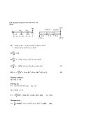
Stability of Structures
Euler’s Formula for Pin-Ended Beams
Extension of Euler’s Formula
Sample Problem 10.1
Eccentric Loading; The Secant Formula
Sample Problem 10.2
Design of Columns Under Centric Load
Sample Problem 10.4
Design of Columns Under an Eccentric Load
© 2002 The McGraw-Hill Companies, Inc. All rights reserved.
10 - 2
Third
Edition
MECHANICS OF MATERIALS
Beer • Johnston • DeWolf
Stability of Structures
• In the design of columns, cross-sectional area is
selected such that
- allowable stress is not exceeded
σ=
P
≤ σ all
A
- deformation falls within specifications
δ=
PL
≤ δ spec
AE
• After these design calculations, may discover
that the column is unstable under loading and
that it suddenly becomes sharply curved or
buckles.
© 2002 The McGraw-Hill Companies, Inc. All rights reserved.
10 - 3
Third
Edition
MECHANICS OF MATERIALS
Beer • Johnston • DeWolf
Stability of Structures
• Consider model with two rods and torsional
spring. After a small perturbation,
K (2∆θ ) = restoring moment
L
L
P sin ∆θ = P ∆θ = destabilizing moment
2
2
• Column is stable (tends to return to aligned
orientation) if
L
P ∆θ < K (2∆θ )
2
P < Pcr =
© 2002 The McGraw-Hill Companies, Inc. All rights reserved.
4K
L
10 - 4
Third
Edition
MECHANICS OF MATERIALS
Beer • Johnston • DeWolf
Stability of Structures
• Assume that a load P is applied. After a
perturbation, the system settles to a new
equilibrium configuration at a finite
deflection angle.
L
P sin θ = K (2θ )
2
PL
P
θ
=
=
4 K Pcr sin θ
• Noting that sinθ < θ , the assumed
configuration is only possible if P > Pcr.
© 2002 The McGraw-Hill Companies, Inc. All rights reserved.
10 - 5
Third
Edition
MECHANICS OF MATERIALS
Beer • Johnston • DeWolf
Euler’s Formula for Pin-Ended Beams
• Consider an axially loaded beam.
After a small perturbation, the system
reaches an equilibrium configuration
such that
d2y
M
P
=
=
−
y
2
EI
EI
dx
d2y
P
+
y=0
2
EI
dx
• Solution with assumed configuration
can only be obtained if
P > Pcr =
π 2 EI
L2
( )
π 2 E Ar 2
π 2E
P
=
σ = > σ cr =
2
A
L A
(L r )2
© 2002 The McGraw-Hill Companies, Inc. All rights reserved.
10 - 6
Third
Edition
MECHANICS OF MATERIALS
Beer • Johnston • DeWolf
Euler’s Formula for Pin-Ended Beams
• The value of stress corresponding to
the critical load,
π 2 EI
P > Pcr =
σ=
σ cr =
=
L2
P
P
> σ cr = cr
A
A
( )
π 2 E Ar 2
L2 A
π 2E
(L r )
2
= critical stress
L
= slenderness ratio
r
• Preceding analysis is limited to
centric loadings.
© 2002 The McGraw-Hill Companies, Inc. All rights reserved.
10 - 7
Third
Edition
MECHANICS OF MATERIALS
Beer • Johnston • DeWolf
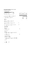
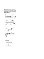
Extension of Euler’s Formula
• A column with one fixed and one free
end, will behave as the upper-half of a
pin-connected column.
• The critical loading is calculated from
Euler’s formula,
Pcr =
σ cr =
π 2 EI
L2e
π 2E
(Le r )2
Le = 2 L = equivalent length
© 2002 The McGraw-Hill Companies, Inc. All rights reserved.
10 - 8
Third
Edition
MECHANICS OF MATERIALS
Beer • Johnston • DeWolf
Extension of Euler’s Formula
© 2002 The McGraw-Hill Companies, Inc. All rights reserved.
10 - 9
Third
Edition
MECHANICS OF MATERIALS
Beer • Johnston • DeWolf
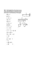
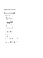
Sample Problem 10.1
An aluminum column of length L and
rectangular cross-section has a fixed end at B
and supports a centric load at A. Two smooth
and rounded fixed plates restrain end A from
moving in one of the vertical planes of
symmetry but allow it to move in the other
plane.
a) Determine the ratio a/b of the two sides of
the cross-section corresponding to the most
efficient design against buckling.
L = 20 in.
E = 10.1 x 10⁶ psi
b) Design the most efficient cross-section for
the column.
P = 5 kips
FS = 2.5
© 2002 The McGraw-Hill Companies, Inc. All rights reserved.
10 - 10
Third
Edition
MECHANICS OF MATERIALS
Beer • Johnston • DeWolf
Sample Problem 10.1
SOLUTION:
The most efficient design occurs when the
resistance to buckling is equal in both planes of
symmetry. This occurs when the slenderness
ratios are equal.
• Buckling in xy Plane:
1 ba 3
I
a2
2
z
12
rz = =
=
12
A
ab
Le, z
rz
=
rz =
a
12
0 .7 L
a 12
• Most efficient design:
Le, z
rz
• Buckling in xz Plane:
ry2
=
Le, y
ry
Iy
A
=
=
1 ab3
12
ab
b2
=
12
ry =
b
12
2L
b / 12
© 2002 The McGraw-Hill Companies, Inc. All rights reserved.
=
Le, y
ry
0 .7 L
2L
=
a 12 b / 12
a 0 .7
=
b
2
a
= 0.35
b
10 - 11
Third
Edition
MECHANICS OF MATERIALS
Beer • Johnston • DeWolf
Sample Problem 10.1
• Design:
Le
2L
2(20 in ) 138.6
=
=
=
ry b 12 b 12
b
Pcr = ( FS )P = (2.5)(5 kips ) = 12.5 kips
σ cr =
σ cr =
Pcr 12500 lbs
=
(0.35b )b
A
π 2E
=
2
(Le r )
(
(
π 2 10.1 × 10⁶ psi
(138.6 b )2
E = 10.1 x 10⁶ psi
12500 lbs π 2 10.1 × 10⁶ psi
=
(0.35b )b
(138.6 b )2
P = 5 kips
b = 1.620 in.
L = 20 in.
FS = 2.5
)
)
a = 0.35b = 0.567 in.
a/b = 0.35
© 2002 The McGraw-Hill Companies, Inc. All rights reserved.
10 - 12
Third
Edition
MECHANICS OF MATERIALS
Beer • Johnston • DeWolf
Eccentric Loading; The Secant Formula
• Eccentric loading is equivalent to a centric
load and a couple.
• Bending occurs for any nonzero eccentricity.
Question of buckling becomes whether the
resulting deflection is excessive.
• The deflection become infinite when P = Pcr
d2y
=
2
dx
− Py − Pe
EI
⎡ ⎛π P ⎞ ⎤
⎟ − 1⎥
ymax = e ⎢sec⎜⎜
⎟
P
2
cr
⎠ ⎦
⎝
⎣
Pcr =
π 2 EI
L2e
• Maximum stress
σ max =
P ⎡ ( ymax + e )c ⎤
1+
⎢
⎥
A⎣
⎦
r2
P ⎡ ec ⎛ 1 P Le ⎞⎤
⎟⎟⎥
= ⎢1 + 2 sec⎜⎜
2
A⎣ r
EA
r
⎠⎦
⎝
© 2002 The McGraw-Hill Companies, Inc. All rights reserved.
10 - 13
Third
Edition
MECHANICS OF MATERIALS
Beer • Johnston • DeWolf
Eccentric Loading; The Secant Formula
σ max = σ Y =
P ⎡ ec ⎛ 1 P Le ⎞⎤
⎟⎥
⎢1 + sec⎜
A ⎣ r 2 ⎜⎝ 2 EA r ⎟⎠⎦
© 2002 The McGraw-Hill Companies, Inc. All rights reserved.
10 - 14
Third
Edition
MECHANICS OF MATERIALS
Beer • Johnston • DeWolf
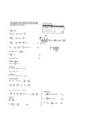
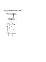
Sample Problem 10.2
The uniform column consists of an 8-ft section
of structural tubing having the cross-section
shown.
a) Using Euler’s formula and a factor of safety
of two, determine the allowable centric load
for the column and the corresponding
normal stress.
E = 29 × 106 psi.
b) Assuming that the allowable load, found in
part a, is applied at a point 0.75 in. from the
geometric axis of the column, determine the
horizontal deflection of the top of the
column and the maximum normal stress in
the column.
© 2002 The McGraw-Hill Companies, Inc. All rights reserved.
10 - 15
Third
Edition
MECHANICS OF MATERIALS
Beer • Johnston • DeWolf
Sample Problem 10.2
SOLUTION:
• Maximum allowable centric load:
- Effective length,
Le = 2(8 ft ) = 16 ft = 192 in.
- Critical load,
Pcr =
π 2 EI
=
2
Le
(
)(
π 2 29 × 106 psi 8.0 in 4
(192 in )2
)
= 62.1 kips
- Allowable load,
62.1 kips
P
Pall = cr =
FS
2
σ=
© 2002 The McGraw-Hill Companies, Inc. All rights reserved.
Pall 31.1 kips
=
A
3.54 in 2
Pall = 31.1 kips
σ = 8.79 ksi
10 - 16
Third
Edition
MECHANICS OF MATERIALS
Beer • Johnston • DeWolf
Sample Problem 10.2
• Eccentric load:
- End deflection,
⎡ ⎛π P ⎞ ⎤
⎟ − 1⎥
ym = e ⎢sec⎜⎜
⎟
⎣
⎝ 2 Pcr ⎠
⎦
⎡ ⎛ π ⎞ ⎤
= (0.075 in )⎢sec⎜
⎟ − 1⎥
2
2
⎠ ⎦
⎣ ⎝
ym = 0.939 in.
- Maximum normal stress,
P ⎡ ec ⎛ π P ⎞⎤
⎟⎥
σ m = ⎢1 + 2 sec⎜⎜
⎟
A⎣
=
r
⎝ 2 Pcr ⎠⎦
31.1 kips ⎡ (0.75 in )(2 in ) ⎛ π ⎞⎤
1+
sec⎜
⎟⎥
2 ⎢
2
2
2
⎝
⎠⎦
3.54 in ⎣
(1.50 in )
σ m = 22.0 ksi
© 2002 The McGraw-Hill Companies, Inc. All rights reserved.
10 - 17
Third
Edition
MECHANICS OF MATERIALS
Beer • Johnston • DeWolf
Design of Columns Under Centric Load
• Previous analyses assumed
stresses below the proportional
limit and initially straight,
homogeneous columns
• Experimental data demonstrate
- for large Le/r, σcr follows
Euler’s formula and depends
upon E but not σY.
- for small Le/r, σcr is
determined by the yield
strength σY and not E.
- for intermediate Le/r, σcr
depends on both σY and E.
© 2002 The McGraw-Hill Companies, Inc. All rights reserved.
10 - 18
Third
Edition
MECHANICS OF MATERIALS
Beer • Johnston • DeWolf
Design of Columns Under Centric Load
Structural Steel
American Inst. of Steel Construction
• For Le/r > Cc
π 2E
σ cr =
2
σ all =
(Le / r )
σ cr
FS
FS = 1.92
• For Le/r > Cc
⎡ (Le / r )2 ⎤
σ cr = σ Y ⎢1 −
2 ⎥
C
2
⎢⎣
c ⎥⎦
σ all =
5 3 L / r 1⎛ L / r ⎞
FS = + e − ⎜⎜ e ⎟⎟
3 8 Cc
8 ⎝ Cc ⎠
σ cr
FS
3
• At Le/r = Cc
σ cr =
© 2002 The McGraw-Hill Companies, Inc. All rights reserved.
1σ
2 Y
Cc2
=
2π 2 E
σY
10 - 19
Third
Edition
MECHANICS OF MATERIALS
Beer • Johnston • DeWolf
Design of Columns Under Centric Load
Aluminum
Aluminum Association, Inc.
• Alloy 6061-T6
Le/r < 66:
σ all = [20.2 − 0.126(Le / r )] ksi
= [139 − 0.868(Le / r )] MPa
Le/r > 66:
σ all =
51000 ksi
(Le / r )
2
=
351 × 103 MPa
(Le / r )2
• Alloy 2014-T6
Le/r < 55:
σ all = [30.7 − 0.23(Le / r )] ksi
= [212 − 1.585( Le / r )] MPa
Le/r > 66:
σ all =
© 2002 The McGraw-Hill Companies, Inc. All rights reserved.
54000 ksi
(Le / r )
2
=
372 × 103 MPa
(Le / r )2
10 - 20
Third
Edition
MECHANICS OF MATERIALS
Beer • Johnston • DeWolf
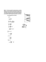
Sample Problem 10.4
SOLUTION:
• With the diameter unknown, the
slenderness ration can not be evaluated.
Must make an assumption on which
slenderness ratio regime to utilize.
• Calculate required diameter for
assumed slenderness ratio regime.
• Evaluate slenderness ratio and verify
initial assumption. Repeat if necessary.
Using the aluminum alloy2014-T6,
determine the smallest diameter rod
which can be used to support the centric
load P = 60 kN if a) L = 750 mm,
b) L = 300 mm
© 2002 The McGraw-Hill Companies, Inc. All rights reserved.
10 - 21
Third
Edition
MECHANICS OF MATERIALS
Beer • Johnston • DeWolf
Sample Problem 10.4
• For L = 750 mm, assume L/r > 55
• Determine cylinder radius:
P 372 × 103 MPa
σ all = =
A
(L r )2
60 × 103 N
πc
c = cylinder radius
r = radius of gyration
=
πc 4 4 c
I
=
=
2
A
2
πc
2
=
372 × 103 MPa
⎛ 0.750 m ⎞
⎜
⎟
⎝ c/2 ⎠
2
c = 18.44 mm
• Check slenderness ratio assumption:
L
L
750mm
=
=
= 81.3 > 55
r c / 2 (18.44 mm )
assumption was correct
d = 2c = 36.9 mm
© 2002 The McGraw-Hill Companies, Inc. All rights reserved.
10 - 22
Third
Edition
MECHANICS OF MATERIALS
Beer • Johnston • DeWolf
Sample Problem 10.4
• For L = 300 mm, assume L/r < 55
• Determine cylinder radius:
σ all =
P ⎡
⎛ L ⎞⎤
= ⎢212 − 1.585⎜ ⎟⎥ MPa
A ⎣
⎝ r ⎠⎦
60 × 103 N
πc 2
⎡
⎛ 0.3 m ⎞⎤
6
= ⎢212 − 1.585⎜
⎟⎥ × 10 Pa
⎝ c / 2 ⎠⎦
⎣
c = 12.00 mm
• Check slenderness ratio assumption:
L
L
300 mm
=
=
= 50 < 55
r c / 2 (12.00 mm )
assumption was correct
d = 2c = 24.0 mm
© 2002 The McGraw-Hill Companies, Inc. All rights reserved.
10 - 23
Third
Edition
MECHANICS OF MATERIALS
Beer • Johnston • DeWolf
Design of Columns Under an Eccentric Load
• An eccentric load P can be replaced by a
centric load P and a couple M = Pe.
• Normal stresses can be found from
superposing the stresses due to the centric
load and couple,
σ = σ centric + σ bending
σ max =
P Mc
+
A I
• Allowable stress method:
P Mc
+
≤ σ all
A I
• Interaction method:
P A
+
Mc I
(σ all )centric (σ all )bending
© 2002 The McGraw-Hill Companies, Inc. All rights reserved.
≤1
10 - 24