Earthquake resistant design of underground structures and pipes
Bạn đang xem bản rút gọn của tài liệu. Xem và tải ngay bản đầy đủ của tài liệu tại đây (198.66 KB, 7 trang )
T~p
chi Ca h9c
Journal of Mechanics, NCNST of Vietnam T. XVII, 1995, No 3 (5 - 11)
EARTHQUAKE RESISTANT DESIGN OF
UNDERGROUND STRUCTURES AND PIPES
DIETER KRAUS
University of the German Armed Forces Munich
Werner Heisenberg Weg 99
8014 Neubiberg /Germany
SUMMARY. Underground Structures and Pipes can be analysed as slender structures
completely embedded in the soil.
For the dynamical analysis soil and structure can be investigated by decoupled structural
models. The horizontal layer system of the soil is modeled as a shear beam while for the structure
a flexural beam is used
Both models will be finally coupled by elastic foundation.
1. INTRODUCTION
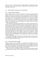
For an earthquake resistant design usually the following verifications have to be carried out:
(1) Stress and strain in longitudinal direction of the.structure, due to the earthquake waves
which are travelling through the soil
The structure has to follow the displacements of the soil, this yields to bending moments,
shear forces and axial forces in longitudinal direction. In cas~ of joints, the movements of the
joints has to be determined to design the joint - construction.
(2) Stress and strain in transverse direction of the s~ructure, due to the reduced internal
friction of the soil.
Depending on the vibrations the internal friction of the soil can significant decrease up to zero.
This effect is called [1} "soilliquifaction,..
Since soil and structure move largely together, for the calculation in transverse direction the
assumptions of the "earth pressure at rest" considering the actual internal friction can be used.
2. NOTATIONS
x, 1Jr-Z :coordinates
u, tJ :
displace~ents
strains
e, 1:
p :
mass density
E:
modulus of elasticity of the soil
G:
modulus of shear of the soil
p.:
Poisson's ratio of the soil
ell :
Shear wave velocity
Cp:
compressional wave velocity
).;
wave length
n-th frequency
fn :
n-th circular frequency
n-th mode
participation factor of the n-th mode
rn:
D:
damping ratio
modal damping of the n-th mode
Dn:
1§ J)B; bending stiffnes of the structure
average modal damping of the n-th mode
Dn:
the acceleration of the soil elements otick
s.:
with the structure
L:
characteristic length of the Winkler beam
t:
length of the structure
Wn:
</>n:
5
3. GENERAL ASSUMPTIONS
Mass distribution and stiffness of the structure does not effect the vibration behaviour of the
soil- it is therefore sufficient to investigate as a first step only the dynamical response of the soil.
The deflections of the soil due to an earthquake can be analysed by using the wave propagation
theory. The ·corresponding vibration model of the soil is assumed as a infinite horizontal layer
system. Only shear wave effect h'as to he taken under consideration.
Stress and strain of the structure are then analysed by the assumption that the structure
follows the movements of the soil with only small relative dellections between soil and structure.
4. DYNAMICAL ANALYSIS OF THE SOIL
Dynamical phenomenons in the soil can be
described by the theory of wave propagation in a
half space.
Two grbups of waves have to be distinguished
-Body waves
u)
- Surface waves
In the group of the body waves (see Fig.l)we
knoW shear waves respectively S- Wave and compressional waves respectively P- Wave and in the
b)
group of the surface waves we distinguish RayleighWave and Love-Waves.
The influence of the surface waves is limited
of a relatively small area. For the followi!>g design
suggestion surface waves are therefore neglected.
In case of shear-waves, soil particles move
perpendicular to the wave propagation. The cor-
c)
-[911111111111111!111
II
II~
1----"!1-----1
--+
direction of wave propagation
responding stress strain state is of pure shear; the
+--+ direction of soil movements
material does not change_s its volume.
Fig. 1. Demonstration of the body waves at a single bar
b) shear wa.vefS-wave,
a) bar at rest,
In case of compressional waves, soil move-
a)
p
c) compressional wave/ P.wave
82 v
at2 dxdydz
ments and wave propagation have the same direc·
tion. The corresponding state of stress and strain
is axial. The elements of the soil are stretched and
compressed.
Due to the different wave velocities compressional waves are much faster than shear waves.
This means that S-Waves and P-Waves do not
affect the structure at the same time.
y,v
On the other hand the movements, cOrre-
sponding to the shear waves are much bigger as
in case of compressional waves.
For practical investigations it is therefore sufficient to consider only shear wave effect~
The differential equations of the ..JVave propagation [4] in a solid body can be found by the
equilibrium of the d' Alembert forces (Fig, 2) and
the alteration of the elastic state of stress.
Fig. 2. Equilibrium condition at a. sOil element
a) pure shear wave action, b) pure compressional wave action
6
a
a
(4.1)
a2..
'ax 2
--=c --
• a• ..
at2
(4.2)
p
2v
2v
-=
c 2 __
at 2
ax•
In equations (4.1) and (4.2) c, and cp means the shear wave velocity and the compressional
wave velocitY
c,=~
Cp
=
(4.3)
,-------:-E,
{1- ~)
p 11 + ~) . (1- 2~)
(4.4)
Equation (4.5a) is a solution of (4.1). In this expression the wave length An can be substituted
by An = c,j In·
• 211'
sm An (x- c,t)
V
= Vo,n
v
, 211'ln( z-c,t)
= Vo,n sm--
(4.5a)
(4.5b)
c,
To describe the complete shape of the shear wave we have to determine a displacement vo,n.
and a frequency In·
To calculate the displacement and the frequency caused by shear deformations, the soil can be
modeled as an infinite layer system [2, 3]{Fig. 3). This layeuystem can further simplified as a shear
beam. H we want to use. conventional computer programms the shear beam can be substituted
by an flexural beam with the bending stiffness B;, lumped masses N; and the condition that the
angel of rotation at each node is zero.
(4.6)
(4.7)
For the dynamical analysis (Fig.4) the response spectrum method may be used, provided that
a spectrum for the bedrock of the layer system is available.
•.•• ·• ·: ', ··; ..... ''' ·: !".
.....
... ·- : ·.. : ·..
.. '.
''·
~
·.. ','
'. .
.
. .~·
:
.
.
·.·:.,:
. ·.'.
.-.·
. ::. :
:·
.. <. ::
H
B·
J
Gj, Qj
/
/
/
/
b)
c)
Fig. 9. Vibration model of the soil
a) infinite parallel layer syste:m,
b) equivalent shear beam,
7
c) equjvalent beam with bending flexure
STRUCTURE
Sa [m/ s 2 )
~
z.o
D:2'Yo
0,5
1
z
3
5
8
10
1Z
s- 1
15
f
n-th Mode
Fig. 4.
Dynamical analysis of the soil
The acceleration of a certain mode is found by the following, well known expressions.
{4.8)
an= if>nf nSa(/n, Dn)
an
Vo,n = _( 2•'fn) 2
{4.9)
5. STRESS RESULTANTS
Stress and strain of the structure are then analysed under the assumption that the structure
follows the displacements of the soil.
This means, that .the dellection curve of the structure is equal to the shape of the wave.
Soil structure interaction has no significant influence on the vibration behaviour of the slender
structure.
In case that the wave propagates in the same direction (Fig.5) as the structure (a= 0),
the stress resultants are found from the product of the bending stiffness of the structure and the
corresponding derivati()ns of the shear wave disp~acements.
~
Wave- front
·-------~-A--------~
1
--
.........
......
,
..........
___
/
............
~:
~ ~
"x
y
'
~x'
Fig. 5. Propagation direction of the wave front
Mn
= ±(E J) B
2..
Vo,n ( --;-In
)2
(5.2)
{5.3)
Qn =
±(E J) 8
Vo,n
Pn =
±(E J) B
2.. ).
Vo,n ( --;-In
8
(5.1)
•
2..
)'
( 7; In
•
{5.4)
The so far described method works under the
structure. Soil- structrure - interaction is of minor influence.
The relation between the displacement of the soil and the displacement of the structure (Fig, 6)
can be estimated by the following equation
4
0.0026('£)
VB
-
vo,n
=
(5.5)
---'-"'+-:--.4
1 + 0.0026
(?)
with
(5.6)
The corresponding parameters are the wave length A and the characteristic length L, which
is describing the elastic foundation between the structure and the soil.
VB /Vc,n
1,0
-
-
-
-
-- ------
Fig. 6. Soil structure interaction
This equation is derived by imposing the soil a statical sinns shaped deflection and the distribution of the bedding forces are also sinus shaped.
With this equation the influence of higher modes can be estimated very easyly.
Higher frequencies yield to a shorter wave length. For ratios >./ L less than 3 the displacement ·
of the structure is less than 20%. In this case the soil displacement will not be transmitted on the
structure. The strUcture remains in rest.
The stress resultants can be significant reduced and influenced by the arrangement of joints.
In a joint. the bending moment vanishes while shear forces usually can be transmitted by the
joint construction.
The influence of joints can investigated by using a beam on elastic foundation.
H for instance the distance of the joints is a quater of the wave length (see Fig. 7a) we will
find the reduced stress resultants by superponing the systems (4.1) and (4.2).
With the diagrammas of Fig. 7 (b) and (c) the reduction factors for bending moments 'IM
and for the shear force at the joint 1'/Q can be found. The corresponding parameters are the wave
length the characteristic length L and the distance t between the joints.
The calculation may be carried out by the following steps:
(1) Calculation of the stress resultants of an infinite structure and for the individual modes
ace. to chapter 4 and 5
Modes with a ration
>./ L
Mn = ±(E J) 8
(5.7)
Qo,n = ±(E J) 8
(5.8}
less than 3.0 may be neclected
9
b)
~M • red. Mn/Mn
L~v(E.nB
Vz
)
G
(1)
. . . ---, -o-ll
Mn
{2)
+
r,
T
0.1
0.2
0.3
~
/
'---<1
l /II
0.4 0.5
j_
c)
Mn
~Q, red Qo,n
t
l/ L
o
/a 0 ,n
6
1.0 L/L •
[, \jle.I)s
0.75
G
0.50
'---, --1 l f..- /
;1~ " ';----<1
O.Z
0.1
o.z
0.3
0.4
Fig. 7. Reduction of stress resultants due to joints
a) superposition method for bendiilg moments, b) reduction for bending moments,
forces at the joints
(2) In case of joints the reduction factors
of Fig. 7.
~M
and
red Mn = Mn
~Q
L/)\
c) reduction for shear
may picked up from the diagramms
~M
red Qo,n = Qo,n
o.s
~Q
(5.9)
(5.10)
(3) Superposition of the individual modes. The simplest and most popular suggestion for
this superposition is the square root of the sum of the squares.
m:ax, red M = ..j'L,(red Mn) 2
max, red Qo
=
'L,(red Qo,n)2
(5.11)
(5.12)
n
The movements of the joints can be rough estimated by the following equations (see Fig. 8)
a l b
t:.K=-·c~
2
iJ
t:.e=-l
2 c,
The joint construction must be able to resist this movements.
10
(5.13)
(5.14)
-8 L-1-_ ___,-I
f --
a)
b)
Fig. 8. Movement at the joints
REFERENCES
Richert E., Hall R., Woods D. Vibrations of soils and foundations. Englewood Cliffs (NJ):
Prentice-Hall 1970.
2. Roesset M. Fundamentals of soil amplification. In: Hansen R.: Siesmic design for nuclear
power plants. Cambridge (Mass.): MIT-Press 1970.
3. Newmark N., Rosenblueth E. Fundamentals of earthquake engineering. Englewood Cliffs (NJ):
Prentice-Hall 1971.
4. Timoshenko S., Goodier N. Theory of elasticity. New York: McGraw"Hill1951.
1.
Received November 11, 1994
TfNH cA.c Kih cA.u ONG TRONG DAT
DUO! TAC DVNG CUA DQNG DAT
Tac gia nghien c.ru "" lam vi~c cda cac kil't ctu ling nAm trong lOng di(t du-6i tac d~ng cda
d<}ng dilt. 0 day, h~ cac lap ngang cda cUt du-gc coi nh1l nhfrng thanh t5 hgp chju citt, con ke't
di:u nhtr nhirng tha.nh chju uSn. GilL thie't dit va. ktft c.tu d~u 13.m vi~c trong tr~ng th.ii d3.n h'Oi.
Sd- d~ng ly thuye't truy~n song va cac gia thiil't neu tren, tac gia da d1ta ra phmtng phap tinh
chuy~n viva. n9i lvc trong ke't c