Parametric study on shear lag effect in super high rise buildings using framed tube system
Bạn đang xem bản rút gọn của tài liệu. Xem và tải ngay bản đầy đủ của tài liệu tại đây (1.34 MB, 8 trang )
RESEARCH RESULTS AND APPLICATIONS
PARAMETRIC STUDY ON SHEAR LAG EFFECT IN SUPER
HIGH-RISE BUILDINGS USING FRAMED TUBE SYSTEM
Bui Thanh Dat1, Nguyen Truong Thang2*, Marina Traykova3
Abstract: Together with the rapid economic development of the country, there have been more and more
buildings higher than 40 stories, so-called super high-rise buildings (SHRB), built in Vietnam. In the design of
such buildings, special attention is always paid on the structural systems for lateral load resistance, in which
the framed tube structure is a popular solution in the world but has not been commonly used in Vietnam. This
paper introduces the shear lag effect, which is the phenomenon of nonlinear distribution in axial stress among
the tube columns due to the difference in shear deformations of the structural system when subjected to lateral loads. A fair number of ten numerical models of reinforced concrete SHRB are analyzed by ETABS software
to investigate the effects of the following parameters on the shear lag ratio: (i) building height; (ii) aspect ratio;
(iii) column spacing; (iv) spandrel depth; and (v) seismic region. Results of the above parametric study can be
used sufficiently in the design for SHRB in Vietnam and are presented in the latter part of the paper.
Keywords: Super high-rise building, framed tube, structure, shear lag, effect.
Received: September 7th, 2017; revised: October 20th, 2017; accepted: November 2nd, 2017
1. Introduction
In the late nineteenth century, super high-rise buildings (SHRB) emerged in the United States of
America. Most important SHRB were built in the USA. An official 10-storey (and 12, after an addition of 2 stories in 1890) building called Home Insurance Building located in Chicago (1885) with 55m high is considered
the world’s first skyscraper [1]. Based on various complex factors, such as economics, aesthetics, technology, municipal regulations and politics, SHRB also appear and rapidly increase in number in other parts of
the world, especially in Asian countries, such as China, Indonesia, Japan, and United Arab Emirate. As the
height of SHRB increased and record was constantly broken, SHRB have become a symbol of prominence.
According to a data published in 2017 [2], there are more than a hundred of SHRB above 300m constructed
in the world and the Burj Khalifa (Dubai-2010) is presently the tallest building in the world, with 163 stories
and 829.8m high. In Vietnam, buildings taller than 40 stories can be conventionally referred to as SHRB.
A SHRB is assumed as a beam cantilevering from the earth which is subjected to axial loading by
gravity and to transverse loading by wind or earthquake. The magnitude of axial loading can be estimated
from the slab areas, so its calculation is not usually considered to be a difficult problem. On the other hand,
the response of a structure to horizontal loads is more complex because it has to carry the external shear,
moment, and torque [3].
In the recent development, a system-based board classification which encompasses most representative SHRB structural systems used today has been proposed. The structural systems of SHRB can be
divided into two categories [4]:
- Interior structures (the major part of the lateral load resisting system is located within the interior of
the building): moment-resisting frame, shear truss/shear wall-frame interaction, outrigger structure.
- Exterior structures (the major part of the lateral load resisting system is located at the building perimeter): framed tube, braced tube, bundle tube, tube-in-tube, diagrid system, super frame.
The framed tube structures, which belong to the second main category of exterior structures, is
among the efficient systems. Basically, the system consists of perimeter closely space columns connected
Postgraduate student, Graduate School - National University of Civil Engineering.
Dr, Faculty of Buildings and Industrial Construction, National University of Civil Engineering.
3
Prof.Dr, Faculty of Structural Engineering, University of Architecture, Civil Engineering and Geodesy.
* Corresponding author. E-mail:
1
2
JOURNAL OF SCIENCE AND TECHNOLOGY IN CIVIL ENGINEERING
Vol. 11 No. 6
11 - 2017
53
RESEARCH RESULTS AND APPLICATIONS
at each floor with deep spandrel girders, thereby creating the effect of a hollow concrete tube. The effective
spacing of perimeter columns in reinforced concrete structures is from 2m to 4m [3,14] whereas the effective
columns’ spacing in steel structures ranges from 4.0m to 6.1m [3,15]. The effective spandrel depth is from
0.9m to 1.52m [14]. On the other hand, framed tube structure allows fewer interior columns, and so creates
more usable floor space. The system acts like a hollow cylinder, cantilevered perpendicular to the ground.
However, these tube systems are affected by shear lag - a nonlinear distribution of stresses across the sides
of the section, which is commonly found in box girder under lateral loads.
Since the concept of framed tube structure has not been applied commonly for SHRB in Vietnam, this
paper aims to introduce about such structural solution and the associated shear lag effect.
2.Shear lag effect
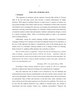
Shear lag effect has been studied for a long time,
with the observation in box girder and any hollow structure
which are subjected to lateral load (Fig. 1). According to
the Euler-Bernoulli elementary theory of bending states, a
plane section remains plane before and after bending. As
a result, the variation of bending stress in the cross section
along flange and web panels must be varying linear. In fact,
the real distribution of these axial stresses is observed not
linear. Due to the shear flow developing in the section, the
panels displace longitudinally in the way that the middle
portion of the flange and web lag behind that of the portion
closer to the corner of the box section, as discussed by [5].
Generally, the lateral load resistance of framed
tube system is highly promoted with the help of tube acFigure 1. Axial stress distribution in box
cantilever beam
tion. When subjected to lateral load, the tube behaves like
a cantilever box beam, where the column deflects in lateral direction and beam deflects in bending. During
the tube action, the shear lag occurs. This type of tubular structure also shows the real distribution of axial
stresses against with the elementary theory of bending, in that the axial stresses applied in the columns of
the peripheral flange are non-uniform and the stress distribution in the web panel are nonlinear.
In framed tube systems, two different modes of shear lag may occur: positive shear lag and negative
shear lag. In which positive shear lag shows the higher axial stress in the corner columns than that of middle
columns, vice versa in negative shear lag. The shear lag ratio is defined to be the ratio between the maximum and the minimum values of columns’ axial stress. Hence, shear lag ratio is greater and smaller than
one for positive shear lag and negative shear lag, respectively.
Shear lag effect in framed tube structures have been studied by researchers. In 1961, framed tube
structural system was introduced [6,7]. Shear lag effect was investigated in a model of a 40-storey framed
tube building. It was found that positive shear lag occurs in the bottom part of the building while negative
shear lag occurs in the top part. Shear lag effect is more significant for buildings with low ratio between the
number of stories and the number of bays. Besides, the origin of negative shear lag is positive shear lag. In
2000, numerical method was used to analyze shear lag effect in framed tube structures with multiple internal
tubes [8]. It was observed that the shear lag reversal points move towards the top of the structure with the
increasing of shear lag and take place at a lower level in internal tubes than those in external tube. In 2005,
the behavior of diagrid system was discussed [5,9]. It was found that the optimal angle varies between 53o
and 76o and this optimal angle reduces as the number of storey decreases. The optimal value of “s”, which
is the ratio between the displacement at the top of the structure due to bending and the displacement due to
shear, would be 3, 4, and 5. It was concluded that the optimal angle for diagrid system varies between 63.4
degree and 71.6 degree, and shear lag effect does not influence the lateral deflection of high-rise buildings.
More recent studies about shear lag effect in tube structures have been conducted. In 2013, shear
lag was studied in braced tube tall structures compared to framed tube tall structures as a solution to resist
shear lag phenomenon [10]. The factors affecting to shear lag ratio were analyzed including the edge columns stiffness, spandrel beam stiffness and diagrid angle are factors which play important roles on reducing
shear lag phenomenon. It is recommended that the behavior of concrete and steel structures should be
investigated separately. In 2014, a study was conducted on hollow structure with a 30-storey tubular framed
building [11]. From the study, it was noted that negative shear lag gets the maximum at top and occurs only
54
Vol. 11 No. 6
11 - 2017
JOURNAL OF SCIENCE AND TECHNOLOGY IN CIVIL ENGINEERING
RESEARCH RESULTS AND APPLICATIONS
after positive shear lag has occurred. In 2015, it was conducted a study of a tube-in-tube structural system
with facade bracing as a solution to mitigate shear lag [12]. It is found that for the heights between 120 and
48 stories, the bracing angle fluctuating between 63.43o and 45o show the least lateral deflection. Other
approaches of reducing shear lag are providing additional structure, such as mage bracings or belt trusses.
Those structures can increase the shear stiffness of the flange and web frames of the framed tube building.
Shear lag effect is an unexpected major phenomenon that controls the design of SHRB using framed
tube system. To the authors’ best knowledge, there have not been much research works on this structural
system applied for HSRB built in Vietnam. In this paper, the parameters that affect the shear lag ratio including: (i) building height; (ii) aspect ratio; (iii) column spacing; (iv) spandrel depth, and (v) seismic region are
investigated by 10 numerical models established in ETABS software. The analysis results are discussed and
conclusions are withdrawn in the latter part of the paper.
3. Parametric study, modeling and analysis
3.1 Structural modeling
Table 1. Dimensions of members in
By using an integrated building design software (ETABS)
60-storey building
established by Computers and Structures Inc. Berkeley [13], a
60-storey reinforced concrete framed tube building, 36m×36m
Items
Dimensions
plan area (Fig. 2), is analyzed. The dimensions and sizes of
Storey height
3.0m
structural members are proposed as shown in Table 1.
Column spacing
3.0m
For controlling lateral deflection and transferring vertical
2
Column size
1.0m × 1.0m
loads, internal columns (1×1m ) are provided. Spandrel beams
with the cross section of 0.5×1m are used to connect the center
Beam size
0.5m × 1.0m
columns as it represents the service core. Inner core columns
Slab thickness
0.25m
are connected to outer perimeter columns with rigid diaphragm
(Fig. 2). The investigated building is subjected to both gravity
loads and lateral loads. The gravity loads are represented by
self-weight of the structure (automatically generated in program
ETABS) and additional permanent load which is assumed as 4
kN/m2. The live load is estimated as in an office building: 3 kN/
m2. High-strength concrete C50/60 is used with mass per unit
volume of 2500 kg/m3.
The seismic load applying on the building is represented
Figure 2. 3D-view and cross section of
by elastic response spectrum in accordance with Eurocode 8
60-storey SHRB
[16], type 1 for ground type C. The reference peak ground acceleration is agR = 0.0959g (in Hanoi) [17]. The investigated building is classified as importance class II, γI =
1.2 [18]. Based on the type of structural system, regularity in elevation and plan, and medium ductility class
(DCM), the behavior factor is assumed as q = 3.9.
3.2 Variation parameters
To have more thorough understanding of the shear lag effect in framed tube system, a parametric
study of framed tube buildings with various arrangements is conducted as follows (Table 2):
- Firstly, three models of 30-, 60-, and 90-storey buildings are analyzed. The column sizes (in mm)
of the 1st to 10th storeys are respectively 700×700, 1000×1000 and 1200×1200 and will be gradually reduced
by 100mm every 10 storeys upwards, i.e. 600×600, 900×900, and 1100×1100 at the 11th to 20th storeys of
the respective 30-, 60-, and 90-storey buildings, and so on.
- The second case focuses on shear lag effect in a building with different aspect ratios, the proportional relationship between width and length of building’s cross section (in plan), as: 1.0 (36m×36m), 0.75
(30m×42m), and 0.5 (24m×48m).
- By changing the column spacing from 2.0m to 3.0m and 4.0m, the shear lag effect is studied in the
third case with three 60-storey models.
- The depths of boundary spandrels are also changed in order to understand more about how this
change affects shear lag. The spandrel depth varies from 1.0m to 1.2m and 1.4m.
- Finally, the building is analyzed under seismic action in different earthquake regions: Hanoi-Vietnam (agR = 0.0959g) [15] and Sofia-Bulgaria (agR = 0.23g) [16].
JOURNAL OF SCIENCE AND TECHNOLOGY IN CIVIL ENGINEERING
Vol. 11 No. 6
11 - 2017
55
RESEARCH RESULTS AND APPLICATIONS
Table 2. Summary of study cases
Parameter
studied
Building
height
Aspect ratio
Column
spacing
Spandrel
depth
Seismic
region
Model
Building
height
Aspect
ratio
Column
spacing
Spandrel
depth
Seismic region
1
30 storeys
1.00
3.0m
1.0m
Hanoi (agR=0.0959g)
2
60 storeys
1.00
3.0m
1.0m
Hanoi (agR=0.0959g)
3
90 storeys
1 .00
3.0m
1.0m
Hanoi (agR=0.0959g)
2
60 storeys
1.00
3.0m
1.0m
Hanoi (agR=0.0959g)
4
60 storeys
0.75
3.0m
1.0m
Hanoi (agR=0.0959g)
5
60 storeys
0.50
3.0m
1.0m
Hanoi (agR=0.0959g)
6
60 storeys
1.00
2.0m
1.0m
Hanoi (agR=0.0959g)
2
60 storeys
1.00
3.0m
1.0m
Hanoi (agR=0.0959g)
7
60 storeys
1.00
4.0m
1.0m
Hanoi (agR=0.0959g)
2
60 storeys
1.00
3.0m
1.0m
Hanoi (agR=0.0959g)
8
60 storeys
1.00
3.0m
1.2m
Hanoi (agR=0.0959g)
9
60 storeys
1.00
3.0m
1.4m
Hanoi (agR=0.0959g)
2
60 storeys
1.00
3.0m
1.0m
Hanoi (agR=0.0959g)
10
60 storeys
1.00
3.0m
1.0m
Sofia (agR=0.23000g)
3.3 Main assumptions for analysis
The modeling and analysis assumptions used for parametric study are summarized as follows:
- The floor slabs in the structure are considered to be rigid diaphragms within their own plane.
- Joints between the spandrel beams and columns are rigid.
- The structural materials are uniform throughout the building height.
- All vertical elements of the building are fully fixed at foundation.
4.Results and discussions
4.1 Shear lag effect in a framed tube building
The following main results are obtained from the numerical modeling. The results are presented as shear lag
ratio - a non-dimensional parameter - defined as the ratio of
axial force in each column to axial force of the middle column
in the same panel.
In Fig. 3, shear lag effect can be observed in a 60-storey
framed tube building (Model 2). The axial stresses in the corner
columns of the flange are higher than stresses in the middle of
the flange at the bottom of the building. Similarly, a non-linear
distribution of stresses can be seen in the web panel.
Furthermore, the shear lag phenomenon varies along
the height of the framed tube structure. The positive shear lag
can be seen in the bottom part of the building, while the top
part shows negative shear lag [7]. The figure also shows that Figure 3. Shear lag ratio in flange and web
panels of building
the degree of shear lag effect at the bottom part of the structure is usually higher than that in the upper part, as discussed in 1994 [5]. Along the height of the building, the
shear lag effect decreases till it becomes zero, at around the 40th storey, then it transfers to negative shear
lag. The negative shear lag ratio, on the other hand, increases from the 40th storey to the top of the building.
Fig. 4 shows the values of shear lag ratio in the corner column at each ten stories. In details, at the
ground storey, the axial stress in corner column can reach approximately one and a half times the axial
stress in middle column. In the web panel, the positive shear lag ratio decreases from 1.40 at the 1st storey
down to 0.53 at the 60th storey. The same trend can be seen in the flange panel. Furthermore, the shear lag
ratio in the web panel is higher than that of the flange panel.
56
Vol. 11 No. 6
11 - 2017
JOURNAL OF SCIENCE AND TECHNOLOGY IN CIVIL ENGINEERING
RESEARCH RESULTS AND APPLICATIONS
Figure 4. Shear lag ratio of corner column along the height of building
4.2 Effect of building height
In the results shown in Fig. 5, the value of shear lag ratio starts to change from positive to negative
at around the 20th storey in the 30-storey building. For the 60-storey and 90-storey buildings, this change
occurs at the 40th storey and the 60th storey, respectively. It can be concluded that the negative shear lag
appears at around two third of the height of SHRB.
Figure 5. Shear lag ratio in flange panel of buildings with different heights
As shown in Fig. 6, the positive shear lag ratio at the corner columns of the 90-storey building is the
highest, around 1.32. The ratios for the 60-storey building and the 30-storey building are slightly smaller,
around 1.28 and 1.15, respectively. For negative shear lag, the general trend is that the degree of negative
shear lag is larger in higher buildings. The “maximum” negative shear lag ratio is nearly 0.62 in the 90-storey
building. It can be seen that shear lag phenomenon generally increases when the building height increases.
Figure 6. Shear lag ratio distribution in flange panel at bottom and top of buildings
JOURNAL OF SCIENCE AND TECHNOLOGY IN CIVIL ENGINEERING
Vol. 11 No. 6
11 - 2017
57
RESEARCH RESULTS AND APPLICATIONS
4.3 Effect of aspect ratio
In Fig. 7, a similar degree of shear lag effect can be observed. At the first ten stories, it is found that
in the square section building (aspect ratio 1.0), positive shear lag is slightly higher than that in rectangular
section building (aspect ratio 0.75 and 0.5). The values are 1.30, 1.23, and 1.19 respectively. Shear lag
ratios are almost the same at other upper stories. Generally, the magnitude of shear lag ratio does not vary
much between these models.
Figure 7. Shear lag ratio distribution in flange panel in buildings with different aspect ratios
4.4 Effect of column spacing
It can be seen in Fig. 8 that the axial stresses of columns in flange panels remain stable from left side
to right side at the two-third height of these buildings. The figure also shows that the shear lag ratio in the
4m-spacing building (1.24) is smaller than those in the 3m-spacing and 2m-spacing buildings (1.27, 1.29).
The difference is more significant in the top part of the building where the negative shear lag occurs and in
the ground storey where the positive shear lag is the highest. This could be explained by the tube action
which is affected by the number and spacing of outer columns.
4.5 Effect of spandrel depth
Besides the variation in the column spacing, structure of framed tube buildings can be varied in the
height of boundary beams, so-called spandrel. Fig. 9 shows that the building with spandrel depth of 1.4m
occurs the lowest shear lag ratio compared to other buildings with lower depth of spandrel. It is suggested
that shear lag effect can be reduced by increasing the depth of spandrel.
Figure 8. Shear lag ratio distribution in flange panel in buildings with different column spacing
58
Vol. 11 No. 6
11 - 2017
JOURNAL OF SCIENCE AND TECHNOLOGY IN CIVIL ENGINEERING
RESEARCH RESULTS AND APPLICATIONS
Figure 9. Shear lag ratio at ground and top storeys for various spandrel depths
4.6 Effect of earthquake region
The seismic load applying on the building is represented by elastic response spectrum in accordance
with Eurocode 8, type 1 for soil profile type C. The reference peak ground acceleration is agR=0.0959g in
Hanoi and agR=0.23g in Sofia. The values of the periods (TB, TC, TD) and of the soil factor (S), which describe the shape of the elastic response spectrum, amount to TB=0.2s, TC=0.6s, TD=2.0s and S=1.15. The
investigated building is classified as importance class II, γI=1.2. Therefore, the peak ground acceleration is
equal to ag=γI*agR=0.11508g. The elastic response spectrum is defined for 5% damping. Based on the type
of structural system, regularity in elevation and plan, and medium ductility class (DCM), the behavior factor
is 3.9. The design curves of response spectrum for Hanoi (Vietnam) [17] and Sofia (Bulgaria) [18] are plotted
in Figs. 10(a) and 10(b), respectively.
The design response spectrum is used in both directions. The CQC rule for the combination of different modes is used. The results of the model analysis in both directions are combined by the SRSS rule.
The load combination of gravity and seismic loads are considered according to EN 1990 is 1.0G+ψ2iQ±EXY,
where G is permanent gravity loads, Q is live load (variable, imposed load), ψ2i=0.3 is reduction factor, and
EXY is the combined seismic action for both directions.
Generally, the magnitude of seismic action in Hanoi-Vietnam is much smaller than that in Sofia-Bulgaria. Fig. 11 shows that shear lag effect occurs in both buildings built in Hanoi and Sofia. Furthermore, the
shear lag ratio of Model 10 in Sofia (1.67) is much higher than that of Model 2 in Hanoi (1.30). This can be
explained by the significant difference in lateral loads acting on buildings. It is reasonable to conclude that
the magnitude of lateral loads contributes significantly to the shear lag effect.
Figure 10. Design response spectrum
Figure 11. Shear lag ratio distribution in flange panel
buildings under seismic action in different regions
5. Conclusions and recommendations
Within the scope of the parametric study conducted in this paper, the following conclusions can be
withdrawn:
- Shear lag effect (positive and negative) is a typical phenomenon existing in framed tube structures
under horizontal loads. Columns in both flange panel and web panel experience non-uniform axial stresses.
JOURNAL OF SCIENCE AND TECHNOLOGY IN CIVIL ENGINEERING
Vol. 11 No. 6
11 - 2017
59
RESEARCH RESULTS AND APPLICATIONS
- Shear lag ratio shows the largest value at the ground floor. The positive shear lag effect decreases
with the increase in floor levels and then transfers to negative shear-lag effect which increases up to the top
of the building.
- Shear lag phenomenon generally increases when the number of stories of building increases and
the negative shear lag appears at two third of the height of super high-rise buildings (SHRB).
- Based on the tube action, the shear lag effect decreases when the column spacing and/or spandrel
depth increases, while the aspect ratio does not significantly affect to the shear lag effect. The shear lag
effect may be controlled by increasing the depth of perimeter spandrels.
- In terms of seismic region, the magnitude of lateral loads acting on SHRB contributes significantly
to the shear lag effect.
This article studies the shear lag effect in framed tube structure where some specific building features
are not modeled. In order to apply the results sufficiently to the design of super high-rise buildings in Vietnam, future research should be dedicated to the influence of the internal reinforced concrete walls around
stairs and elevators, as well as the effects of taking into account of the construction sequence. Besides, it is
needed to investigate the behavior of concrete and steel structures separately. Furthermore, the influences
of both wind load and earthquake load should also be taken into consideration.
References
1. Theguardian (2017), 02/04/2017.
2. The Skyscraper Center (2017), , 05/03/2017.
3. Bungale S. T. (2010), Reinforced concrete design of tall buildings, Boca Ratin, FL: CRC Press, Taylor &
Francis Group.
4. Ali M.M, Kyoung S.M. (2007), "Structural Developments in Tal Buildings: Current trends and future prospects", Architectural Science Review, 50(3):205-233.
5. Johan L. (2007), Investigation of shear lag effect in high-rise buildings with diagrid system, Master's thesis
of Engineering - Massachusetts Institute of Technology.
6. Lehigh University (2017), 02/04/2017.
7. Y. Singh, A. K. Nagpal (1994), "Negative shear lag in framed tube buildings”, Journal of Structural Engineering, 120(11):3105-3121.
8. Hong G., Yew-Chaye L.K.K.L (2000), "Simplified analysis of shear lag in framed tube structures with multiple internal tubes", Computational Mechanics, 25(5):447-458.
9. K. S. Moon (2005), Dynamic relationship between technology and architecture in tall buildings, PhD Thesis - Massachusetts Institue of Technology.
10. Farshid N., Payam A. (2013), "Investigation of the shear lag phenomenon and structural behavior of
framed tube and braced tube tall structures", International Conference on Civil Engineering, Architecture &
Urban Sustainable Development, Tabriz, Iran, 356-366.
11. Yogesh D.N., Mohankumar P.H. (2014), "Analysis of shear lad effect in hollow structures", International
Journal of Engineering Research & Technology (IJERT), 3(7).
12. Himanshu G., Ravindra K.G (2015), "Mitigating shear lag in tall buildings", International Journal of Advanced Structural Engineering, 7(3):269-279.
13. Computers & Structures, Inc (2016), ETABS 2016 - CSi Analysis reference manual, Berkeley, California, USA.
14. Amr S. E., Luigi D.S. (2008), Fundamentals of Earthquake Engineering, A John Wiley & Son Ltd, Publication.
15. Marcel D. (2005), Wind and Earthquake Resistant Buildings - Structural Analysis and Design, New York.
16. European Standard (2005), Eurocode 8: Design of structures for earthquake resistance, European Committee for Standardization.
17. TCVN 9386:2012 (2012), Design of structures for earthquake resistance, Ministry of Science and Technology.
18. Bulgarian Standard (2005), Eurocode 8: Design of structures for earthquake resistance - National Annex
to BDS EN 1998-1:2005, Bulgarian Institute for Standardization.
60
Vol. 11 No. 6
11 - 2017
JOURNAL OF SCIENCE AND TECHNOLOGY IN CIVIL ENGINEERING