Analyse the disk closed cycle MHD generator performance with the influence of channel characteristics
Bạn đang xem bản rút gọn của tài liệu. Xem và tải ngay bản đầy đủ của tài liệu tại đây (522.47 KB, 11 trang )
TAẽP CH PHAT TRIEN KH&CN, TAP 19, SO K5- 2016
Analyse the disk closed cycle MHD
generator performance with the influence
of channel characteristics
Le Chi Kien
Ho Chi Minh city University of Technology and Education
(Manuscript Received on March 12th, 2015, Manuscript Revised April 04th, 2016)
ABSTRACT
The enthalpy extraction ratio is one of the
most significant parameter of a disk closed cycle
possible to maintain a high flow velocity inside
the channel and a high Hall parameter. The
MHD generator. There are two methods to
implemention of inlet swirl is possible to
improve the enthalpy extraction, those are the
increase of channel cross-sectional area ratio
maintain a low static pressure inside the channel
and the enthalpy extraction ratio rises due to the
and the implementation of inlet swirl. In this
study, the mechanism of enthalpy extraction
increase of Hall parameter. In addition, the
channel cross-sectional area ratio increases due
improvement has been confirmed by the twodimensional numerical calculation. As a result,
to the swirl implementation, the static pressure is
kept low, and the channel inlet flow velocity
by increasing the channel cross-sectional area
increases. This also leads to the increase of
ratio of the disk MHD generator, the increase of
static pressure and the velocity deceleration can
enthalpy extraction ratio, that is the increase of
output power.
be suppressed due to the Lorentz force, and it is
Keywords: Enthalpy extraction, cross-sectional area ratio, inlet swirl, two-dimensional calculation.
1. INTRODUCTION
Disk closed cycle MHD (CCMHD) power
enthalpy extraction. They are the increase of
generation directly converts the thermal and
kinetic energy into the electrical energy by
channel cross-sectional area ratio and the
implementation of inlet swirl.
flowing a electrical conduction working fluid in
the radial direction into a disk channel which is
applied by a magnetic field. Recently, CCMHD
generator has revealed experimentally a high
enthalpy extraction ratio by using a disk-shaped
channel. There are two methods to improve the
The improvement of enthalpy extraction
ratio due to the increase of generator channel
cross-sectional
area
ratio
is
revealed
experimentally by using a blowdown equipment
and shock tube [1]. It is known that the increase
of channel cross-sectional area ratio opposes the
Trang 13
SCIENCE & TECHNOLOGY DEVELOPMENT, Vol 19, No.K5- 2016
velocity deceleration due to strong Lorentz force,
and leads to a high flow velocity inside the
generator channel. At this time, it puts a low
static pressure inside the generator channel and
may achieve a high Hall parameter. The
improvement of enthalpy extraction is indicated
by the quasi one-dimensional calculations [2].
2.
MHD
PLASMA
EQUATIONS
AND
BASIC
In this study, the non-equilibrium plasma
using a two-temperature model is described [8].
The following assumptions have been proposed
for the plasma of CCMHD generator.
(1) Ignore the displacement current.
The improvement of enthalpy extraction
ratio by the implementation of inlet swirl (swirl
(2) Electrical neutral is maintained.
flow) is described by experiments using the
shock tube, and this has achieved a high enthalpy
(3) Magnetic Reynolds number is rather small,
and the magnetic field is constant.
extraction of over 30% [3]. The low static
pressure inside the channel is preserved due to the
inlet swirl, and the maintain of a high Hall
parameter is similarly indicated by the quasi-onedimensional calculations [4].
The quasi one-dimensional calculation time
is short, and this calculation has been used to
describe the qualitative trend of the experimental
results because it is possible to change many
parameters. However in the quasi onedimensional calculation, the boundary layer
displacement thickness must be assumed,
therefore in recent years, a boundary layer twodimensional calculation has been proposed, but
the suitability should be studied because it is
clearly that the boundary layer thickness is
significantly
different
with
different
operational condition [5,6,7]. In this study, the
mechanism of enthalpy extraction improvement
which considers the inlet swirl and the increase
of the channel cross-sectional area ratio has been
confirmed by the two-dimensional numerical
calculation. In addition, this study not only
examines the behavior of a boundary layer with
different inlet swirl and channel shape but also
shows the characteristics of the flow field that has
received a strong Lorentz force.
Trang 14
(4) Influence of ion slip can be ignored.
Furthermore, it is assumed that the
following equations are expressed in a cylindrical
coordinate system and the uniformity in the
circumferential direction ∂/∂θ=0. Basic equations
are composed of non-equilibrium plasma
equations and the governing equations in the flow
field that describes the working fluid. Symbols
used in this study agree with the habitual
symbols. The details of calculation method and
basic equations are refered in [6, 7].
2.1 Governing equations
The governing equations of the flow field
are written in the forms of very famous
compressibility Navier-Stokes equations, and the
MHD effect is applied to the energy and
momentum equation. The state equations are also
used appropriately.
d
u
dt
(1)
dur
j B u 2 1 p
Vr
dt
r r
(2)
du
jB uu
r r V
dt
r
(3)
TAẽP CH PHAT TRIEN KH&CN, TAP 19, SO K5- 2016
du z
1 p
Vz
dt
z
(4)
2
j
dT
c
p u
H
dt
(5)
Here, V is viscosity term, and H in energy
equation shows the dissipation due to the heat
equations are put together the following two
equations by MHD approximation.
Er Ez
0
z
r
(11)
1
rjr jz 0
r r
z
(12)
conduction and viscosity.
2.3 Boundary conditions and analysis method
2.2 Plasma equations
The area for numerical analysis is from the
throat to the downstream end of the cathode.
Equations describing the plasma consist of
ionization equations, generalized Ohm's law
equations, and energy equations.
Physical quantity for the generator symmetric
plane (z=0) is assumed to be symmetric, and only
The energy equations ignore the time and
the upper surface is analysed. The ionization
equation and the governing equation of flow field
spatial gradient, and they are expressed as the
are solved by using the CIP method [9]. To solve
algebraic equations by assuming the relaxation
time of the electron temperature is much shorter
and combine the Maxwell equation and the
generalized Ohm's law equation, the potential
than the relaxation time of the electron number
density.
function is defined and this is solved by using
dni
ni u ni
dt
element method. The common conditions used
jr
1 2
(6)
Er u B ur B
(7)
Er u B ur B
j
1 2
(8)
jz Ez
(9)
j
2
j
m
3ne me k Te T
j
j
i
for the calculation are shown in Table 1. Outlet
boundary is a free outflow condition. Applied
magnetic field uses a magnetic field distribution
that has been used in Fuji-1 MHD disk generator
[10]. This magnetic field is 4.7 [T] at the inlet and
2.5 [T] at the outlet after applying to downstream
and reducing gently.
3
ni kTe i (10)
2
Here, is the Hall parameter, is the
electrical conductivity, ni
the Galerkin method which is one type of finite
Table 1. Calculation conditions.
Working gas
Seed fraction
Wall temperature
Ar + Cs
2ì10-4
[K] 500
the ion number
density, ni is the ion number density that is
Inlet Boundary Condition
generated per unit time, j is the collision
frequency between electron and j-particle, i is
Stagnation temperature
Electron temperature
[K] 2000
[K] 3000
the i-particle ionization potential. Maxwell's
Trang 15
SCIENCE & TECHNOLOGY DEVELOPMENT, Vol 19, No.K5- 2016
3. RESULTS AND DISCUSSION
3.1 Influence of channel cross-sectional area
cross-sectional area ratio has been achieved by
the load resistance of 0.5Ω.
40
ratio
(a)
(b)
(c)
0.02
(a)
Cathode
Channel
Anode
Channel Height [m]
Nozzle
(b)
0.01
Throat
0.2
Radius [m]
20
0
0.1
(c)
0
Enthalpy Extraction [%]
0.03
0.4
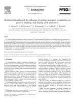
Figure 1. Generator channel height with different
cross-sectional area ratios.
In order to investigate the influence of
channel cross-sectional area ratio to the enthalpy
extraction ratio, the calculation for three different
cross-sectional area ratios of disk MHD
generator is carried out and shown in Fig. 1. The
channel height in this figure is the distance from
the wall to the symmetrical plane of the
generator. Fig. 1 represents the scale expended in
1
Load Resistance []
10
Figure 2. Relationship of enthalpy extraction and
load resistance.
The enthalpy extraction ratio increases with
the increasing of the cross-sectional area ratio.
When comparing the enthalpy extraction of the
channel (a) and channel (b), the enthalpy
extraction at 0.5Ω load resistance increases,
however, it remains to increase about 1% at the
load resistance which is bigger or smaller than
this value and when the cross-sectional area ratio
is bigger, the decreasing of the enthalpy
extraction which is out of the optimum load
resistance is remarkable.
the z-direction. The graph (a), (b), (c) is in order
Fig. 3 shows the radial direction distribution
of decreasing cross-sectional area ratio of the
channel. The channel of the graph (b) has almost
of the quantities in the symmetrical plane (z=0)
for each cross-sectional area ratio when the
the same shape as the channel of MHD device
refered in [10]. The stagnation pressure is
maximum output is obtained at the load
resistance of 0.5Ω. The static pressure in the
calculated at 0.60MPa with each cross-sectional
area ratio, and the inlet swirl is calculated at 0.
generator channel remains low as the channel
Fig. 2 shows dependence of the enthalpy
extraction ratio on the load resistance for each
cross-sectional area ratio, respectively. The
maximum of enthalpy extraction ratio in each
Trang 16
cross-sectional area ratio increases. As the static
pressure is low, the collision frequency between
electrons and heavy particles reduces,
consequently
Hall
parameter
increases.
Moreover in the channel (a), (b) with large crosssectional area ratio, the velocity deceleration of
TAẽP CH PHAT TRIEN KH&CN, TAP 19, SO K5- 2016
working fluid is not sudden as in the channel (c).
Thus, as the channel cross-sectional area ratio
extraction is confirmed when the flow velocity
and Hall parameter is high. In addition, with the
enlargement of the channel cross-sectional area
ratio, the flow velocity at the channel inlet rises,
and this leads to a rise of enthalpy extraction
RL=2.0
0.02
0.01
ratio.
0
0.2
Radius [m]
1500
Boundary Layer Thickness [m]
500
(a)
(b)
(c)
0
RL=2.0
0.01
0
0.2
Radius [m]
0.4
Channel (b)
0.2
Radius [m]
0.4
6
(b)
Static Pressure [Pa]
RL=0.5
105
Boundary Layer Thickness [m]
Radial Flow Velocity [m/s]
1000
0.01
RL=0.5
RL=2.0
0
0.2
Radius [m]
0.4
Channel (c)
Figure 4. Boundary layer thickness with different
cross-sectional area ratios.
104
(a)
(b)
(c)
103
0
0.4
Channel (a)
(a)
10
Channel height
Boundary layer thickness
the Lorentz force, and the increasing of both the
electromotive force urB and the enthalpy
RL=0.5
Boundary Layer Thickness [m]
enlarges, the deceleration of working fluid and
the rise of static pressure can be suppressed by
Next, the development state of boundary
layer in each channel is shown in Fig. 4. In
channel (a) particularly, the development of
0.2
Radius [m]
0.4
Figure 3. Radial distribution of radial flow velocity
and static pressure with different area ratios.
boundary layer is great, and the boundary layer in
the channel outlet vicinity almost spreads
throughout the channel and it will extend to the
nozzle when the load resistance is high. As the
Trang 17
SCIENCE & TECHNOLOGY DEVELOPMENT, Vol 19, No.K5- 2016
channel inlet is lower comparing to the case of
low load resistance. In contrast, the extent of the
boundary layer in the nozzle is small even when
the load resistance is high in the channel (c). With
the enlargement of the channel cross-sectional
area, the boundary layer thickness increases that
thickness, and the increasing of that thickness is
(b) 10
Static Pressure [Pa]
boundary layer extends greatly to the nozzle, the
flow velocity and the Hall parameter in the
105
104
S=0.0
S=0.5
remarkable at a high load resistance. The power
output in channel (a), (b) increases significantly
S=1.0
10
in the low load resistance case in which the extent
load resistance is high, the increasing of power
output is small but the boundary layer develops
greatly and the decrease of the influence which
increases the cross-sectional area ratio can be
explained.
3.2 Influence of inlet swirl
3
0
0.4
0.2
Radius [m]
0.4
0.2
Radius [m]
0.4
(c)
0
–2
S=0.0
S=0.5
–4
S=1.0
(a)
0
1000
(d) 30
S=0.0
S=0.5
S=1.0
500
Hall Parameter
Radial Flow Velocity [m/s]
0.2
Radius [m]
[×105]
Faraday Current Density [A/m2]
of boundary layer is slight as shown in Fig. 2
comparing to the channel (c). However, when the
6
S=0.0
S=0.5
S=1.0
20
10
0
0.2
Radius [m]
0.4
0
Figure 5. Radial distributions with various inlet swirl.
Trang 18
TAẽP CH PHAT TRIEN KH&CN, TAP 19, SO K5- 2016
0.02
Swirl S is defined as the ratio of the radial
Cathode
flow velocity to the circumferential flow velocity
Mach number at the throat is fixed at 1.0, the
radial flow velocity is small due to the swirl, and
Height [m]
(momentum). The swirl calculations were carried
out with S=0, 0.5, 1.0 in the throat. Since the
1000 [m/s]
the heat input expressing by urcpTA (A is throat
cross-sectional area) decreases. The calculation
0.01
Anode
0
0.1
0.2
used the channel (b) and the stagnation pressure
Inlet swirl
Inlet ur
0.0
0.5
0.02
Cathode
1000 [m/s]
Height [m]
Table 2. Dendence of power output and
enthalpy extraction on inlet swirl.
0.01
Anode
0
0.1
1.0
0.2
[m/s] 721.3 675.2 510.1
Thermal input
[MW] 3.75
3.3
2.65
Power output
[MW] 1.18
1.24
1.07
0.4
(a) S = 0.0
was set to 0.45MPa. Table 2 shows the achieved
enthalpy extraction. As the swirl is provided, the
heat input declines and then the power output
reduces, however, the enthalpy extraction rises.
0.3
Radius [m]
0.3
Radius [m]
0.4
(b) S = 0.5
0.02
Cathode
Enthalpy extraction [%] 31.6
37.7
40.3
Fig. 5 shows the radial distribution of
various quantities in the symmetrical plane. The
static pressure distribution is kept low as the swirl
is provided. Although the radial flow velocity at
the throat is small because of providing a swirl, it
is nearly the same value in the channel inlet. This
is because there is a difference occuring in the
isentropic flow by the swirl, and there is a
behavior to change the cross-sectional area in the
flow direction by providing a swirl [11]. As a
result, in the nozzle in which the isentropic flow
is nearly the same, a high Mach number can be
obtained from the channel inlet, while the static
pressure is small and the Hall parameter is large.
Height [m]
1000 [m/s]
0.01
Anode
0
0.1
0.2
0.3
Radius [m]
0.4
(c) S = 1.0
Figure 6. Distribution of radial flow velocity with
various inlet swirl.
The increase of Hall parameter leads to a
substantial
decrease
/(1+2)
in
electrical
conductivity in the circumferential direction, the
Faraday current density in Eq. (8) decreases.
Therefore, the Lorentz force in the channel inlet
is weakened, and a low static pressure, as well as
a high Hall parameter, is maintained throughout
the channel. From the above results, by the
implementation of the inlet swirl, a high Hall
Trang 19
SCIENCE & TECHNOLOGY DEVELOPMENT, Vol 19, No.K5- 2016
parameter throughout the channel can be
maintained and the increase of enthalpy
velocity near the wall is dragged in the
mainstream and changes to a negative value.
extraction ratio is clearly shown.
When the swirl is provided in the positive
direction at the inlet, the unique flow field, where
The
distribution
of
the
radial
and
circumferential flow velocity of the disk MHD
generator are shown in Figs. 6 and 7. The
difference in the radial component of flow
the positive direction flow exists in the negative
direction wall vicinity in the mainstream, is
specially remarkable.
0.02
velocity due to the swirl is remarkably seen in the
channel inlet while it is nearly the same profile in
line that connects the area of ur=0. In this case,
Height [m]
the other areas. Fig. 8 shows the flow separation
line for each swirl. The flow separation line is the
Cathode
250 [m/s]
0.01
Anode
the fluid flows radially outward in the
mainstream from the flow separation line, but the
0
0.1
boundary layer inside the flow separation line is
exfoliated and the vortex is generated in the flow.
Cathode
250 [m/s]
the
circumferential
direction
Height [m]
Next,
channel, the direction of Lorentz force (jr×B)
acting on the working fluid is taken as the
negative
direction
of
the
0.01
Anode
0
0.1
0.2
component of the flow velocity. When an inlet
swirl is not provided, the radial flow in the nozzle
0.4
0.02
Cathode
250 [m/s]
Height [m]
vicinity (dotted line) near the upstream part of the
channel, the circumferential component is found
0.3
Radius [m]
(b) S = 0.5
circumferential
is bent in the negative direction by the Lorentz
force in the channel. When focusing on the wall
0.4
0.02
is moved downstream together with the swirl and
component is focused on. When the electric
current flows from the anode to the cathode in the
0.3
Radius [m]
(a) S = 0.0
For small Lorentz force at the generator inlet, as
the swirl is provided, the exfoliation component
that area is also small.
0.2
0.01
Anode
to be a positive value. This is because the Hall
current flows backwards through the area where
the electromotive force is weak inside the
0
0.1
0.2
0.3
Radius [m]
0.4
(c) S = 1.0
boundary layer. Because the Lorentz force acting
in the negative direction in the mainstream is
Figure 7. Distribution of azimuthal flow velocity
stronger than the Lorentz force acting in the
with various inlet swirl.
positive direction at the wall vicinity, the flow
Trang 20
TAẽP CH PHAT TRIEN KH&CN, TAP 19, SO K5- 2016
0.016
sectional area ratio of the disk MHD generator,
the increase of static pressure and the velocity
Height [m]
Channel height
deceleration can be suppressed due to the Lorentz
force, and it is possible to maintain a high flow
0.012
0.008
0.004
0
velocity inside the channel and a high Hall
parameter. Therefore, both the electromotive
S=1.0
S=0.5
S=0.0
0.2
Radius [m]
force and enthalpy extraction increases.
Moreover, the increasing of channel cross0.4
Figure 8. Separation line with various inlet swirl.
In this MHD generator, the Hall parameter
is about 8, the radial flow velocity ur is about 700
sectional area ratio is not effeted at a high load
resistance which acts a large Lorentz force on the
fluid because of the large development of
boundary layer.
(2) By implementing an inlet swirl, it is
[m/s], the circumferential flow velocity u is less
possible to maintain a low static pressure inside
the channel and the enthalpy extraction ratio rises
than 100 [m/s], and because the electromotive
force uB is much smaller than the electromotive
due to the increase of Hall parameter. If there is a
force urB, the influence on the power generation
performance of such flow field is small.
4. CONCLUSIONS
Based on the increase of enthalpy extraction
in the disk CCMHD generator, which was shown
due to the increase of channel cross-sectional
area ratio and the implementation of inlet swirl,
the enthalpy extraction improvement mechanism
was verified using a two-dimensional numerical
calculation including the boundary layer. As a
result, the following is concluded.
(1) By increasing the
channel
swirl in the flow, the cross-sectional area which
is obtained from the flow direction crosssectional area and the generator channel height is
different. As a result, the channel cross-sectional
area ratio increases due to the swirl
implementation, the static pressure is kept low,
and the channel inlet flow velocity increases.
This also leads to the increase of enthalpy
extraction ratio. The structure of the flow field
with the circumferential velocity component
which is generated by the Lorentz force and the
state of boundary layer inside the channel is also
shown.
cross-
Trang 21
SCIENCE & TECHNOLOGY DEVELOPMENT, Vol 19, No.K5- 2016
Phân tích hoạt động của máy phát điện Từ
thuỷ động loại đĩa chu trình kín với ảnh
hưởng của các thuộc tính ống dẫn
Lê Chí Kiên
Trường Đại học Sư phạm Kỹ thuật TP.HCM
TÓM TẮT
Tỉ chiết enthalpy là một trong những thông
ống dẫn và tham số Hall ở giá trị cao. Việc thực
số quan trọng nhất của máy phát điện Từ thuỷ
động loại đĩa chu trình kín. Có hai phương pháp
hiện dòng xoáy ngõ vào có thể giữ cho áp suất
tĩnh thấp bên trong ống dẫn đồng thời tăng tỉ
cải thiện tỉ chiết enthalpy này là tăng tỉ số mặt cắt
ống dẫn và thực hiện dòng chảy xoáy ngõ vào.
chiết enthalpy do bởi sự tăng của tham số Hall.
Hơn nữa các thông số khác như tỉ số mặt cắt ống
Bài báo này đã khẳng định cơ chế cải thiện tỉ
chiết enthalpy bằng những tính toán số hai chiều.
dẫn sẽ tăng do dòng xoáy ngõ vào, áp suất tĩnh
sẽ được giữ ở mức thấp và vận tốc dòng chảy ngõ
Kết quả là việc tăng áp suất tĩnh và sự giảm tốc
vào ống dẫn sẽ tăng. Điều này dẫn đến việc tăng
của dòng chảy có thể được kìm chế bằng lực
Lorentz và có thể giữ tốc độ dòng chảy bên trong
tỉ chiết enthalpy, có nghĩa là tăng công suất điện
phát ra.
Từ khóa: Tỉ chiết enthalpy, tỉ số mặt cắt, dòng xoáy ngõ vào, tính toán hai chiều .
REFERENCES
[1]. Ko Kawane, Satoshi Shimada, Jiro
Kasahara, Akiko Matsuo, The influence of
[3]. Mustafa Turkyilmazoglu, MHD fluid flow
and heat transfer due to a shrinking rotating
heat transfer and friction on the impulse of a
disk, Computers & Fluids, 90, 51-56 (2014).
detonation tube, Combustion and Flame,
158, 10, 2023-2036 (2011).
[2]. Kraig Frederickson, Sergey Leonov,
Munetake Nishihara, Evgeny Ivanov, Igor
V. Adamovich, Walter R. Lempert, J.
William Rich, Energy conversion in high
enthalpy
flows
and
non-equilibrium
plasmas, Progress in Aerospace Sciences,
72, 49-65 (2015).
Trang 22
[4]. Leila Rajaee, Homayoon Eshraghi, Roman
O. Popovych, Multi-dimensional quasisimple waves in weakly dissipative flows,
Physica D: Nonlinear Phenomena, 237, 3,
405-419 (2008).
[5]. Donghun Park, Seung O. Park, Influence of
two-dimensional smooth humps on linear
and non-linear instability of a supersonic
TAẽP CH PHAT TRIEN KH&CN, TAP 19, SO K5- 2016
boundary layer, Computers & Fluids, 79,
140-149 (2013).
Modified
[6]. S.E. Aly, Injection effect on two
dimensional boundary layer, Energy
Conversion and Management, 41, 6, 539550 (2000).
[7]. Jeremy Gartner, Michael Amitay, Effect of
boundary layer thickness on secondary
structures in a short inlet curved duct,
International Journal of Heat and Fluid
Flow, 50, 467-478 (2014).
[8]. Takayuki Watanabe,
Nobuhiko
Atsuchi,
[9]. Seung-Jun Lee, Ik Kyu Park, Jae Jun Jeong,
Masaya Shigeta,
Two-temperature
chemically-non-equilibrium modeling of
argon induction plasmas with diatomic gas,
CIP-CSL/FV
method
for
incompressible flows, Computers & Fluids,
86, 240-250 (2013).
[10]. M. Aoyagi, S. Ito, H. Hashizume, Numerical
study of the MHD flow characteristics in a
three-surface-multi-layered channel with
different
inlet
conditions,
Fusion
Engineering and Design, 89, 7-8, 12271231 (2014).
[11]. T. Inoue, M. Matsui, H. Takayanagi, K.
Komurasaki, Y. Arakawa, Effect of swirl
flow on an atmospheric inductively coupled
plasma supersonic jet, Vacuum, 80, 11-12,
1174-1178 (2006).
International Journal of Heat and Mass
Transfer, 49, 25-26, 4867-4876 (2006).
Trang 23