FPGA Implementation of Mimo E-SDM for future communications wireless networks
Bạn đang xem bản rút gọn của tài liệu. Xem và tải ngay bản đầy đủ của tài liệu tại đây (447.79 KB, 11 trang )
TAẽP CH PHAT TRIEN KH&CN, TAP 17, SO K2- 2014
FPGA Implementation of Mimo E-SDM for
future communications wireless networks
Nguyen Trung Hieu
Bui Huu Phu
DCSELAB, University of Technology,VNU-HCM
(Manuscript Received on December 11th, 2013; Manuscript Revised September 09th, 2014)
ABSTRACT:
Multiple-input multiple-output (MIMO)
systems applying the Eigenbeam-Space
Division Multiplexing (E-SDM) technique
can be considered as optimal MIMO
systems because of providing the highest
channel
capacity
and
good
communications reliability. In the systems,
orthogonal transmission beams are formed
between transmit and receive sides; and
also optimal transmit input data are
adaptively allocated. In addition, a simple
detection can be used at receiver to totally
eliminate
sub-stream
interference.
Therefore, MIMO E-SDM systems have
been considered as a good potential
technology for future high speed data
transmission networks. Although there
have been a lot of technical papers
evaluated the systems based on theory
analyses
and/or
computer-based
simulation, just few ones have been
considered the MIMO E-SDM systems
based on hardware design. The main
contribution of this paper is to present our
own design and implementation of 2x2 and
2x3 MIMO E-SDM systems on FPGA
Altera Stratix DSP Development KIT using
Verilog HDL, an important step before
going to make integrated circuits. The biterror rate performance the consumption for
our design of these systems have shown
that our design is successful.
Keywords: MIMO, E-SDM, ZF, FPGA, hardware design.
1. INTRODUCTION
Multiple-input multiple-out (MIMO) systems
802.11, 3GPP Long Term Evolution, and WiMAX
have been considered as a high speed data
When channel state information (CSI) is not
[13].
transmission technology. The channel capacity of
available
the systems can increase significantly and is
multiplexing (SDM) technique is used for data
proportionally to the number of transmit (TX) and
transmission. In the technique, data resources,
receive (RX) antennas without additional power
power level and modulation scheme, are allocated
and bandwidth compared with single-input single-
equally
out systems. The systems have been standardized
However, when CSI is available, an eigenbeam-
to be used in modern networks such as IEEE
space division multiplexing (E-SDM) is used [7-
at
to
transmitter,
all
transmit
spatial
division
sub-streams
[4-6].
Trang 79
SCIENCE & TECHNOLOGY DEVELOPMENT, Vol 17, No.K2- 2014
9]. The MIMO E-SDM systems are also called
model in an automated process. Based on the
singular value decomposition MIMO (SVD
design, we evaluate bit-error rate (BER) of the
MIMO) systems [10] or MIMO eigenmode
systems and also compare the consumption of
transmission systems [11].
FPGA elements for our design of the systems. A
orthogonal
part of the paper has been presented in [14].
beamforming is formed based on the eigenvectors
Moreover, we have also extended our study of
obtained from eigenvalue decomposition using a
single carrier MIMO E-SDM systems (presented
MIMO channel matrix. To increase quality of the
in the paper) to multi-carrier MIMO E-SDM
systems, the E-SDM technique has an innovation
systems [15]. In the multi-carrier systems,
in transmitting. A new feature of this algorithm is
Othogonal
the calculation of the bit error probability of each
(OFDM) technique is used to improve frequency
flow with many cases of demodulation. In the
efficiency and eliminate inter-symbol interference.
systems, a simple receive weight method can
The paper is organized as follows. In the next
In
E-SDM
techniques,
an
Frequency
Division
Multiplexing
inter-
section, an overview of MIMO E-SDM systems is
substream interference, and maximum channel
presented. In section III, we will show our design
capacity is obtained. These advantages make the
and hardware implementation of the MIMO E-
MIMO E-SDM technology a promising candidate
SDM system. The results and discussion of our
for future high-rate wireless applications.
implementations are shown in section IV. Finally,
demultiplex
received
signals
without
There have been a lot of technical papers studied
and evaluated about the MIMO E-SDM systems
based on theory analyses and/or computer-based
conclusions are drawn in Section V.
2. OVERVIEW OF MIMO E-SDM
SYSTEMS
simulation [7-11]. However, just few ones have
considered the systems based on hardware
Input
s1
x1
s2
x2
MUX
implementation [12,13].
The main contribution of the paper is to present
TX
WEIGHT
MATRIX
sK
Beam1
Beam2
xN
tx
our own detailed design and implementation of the
MIMO E-SDM systems on FPGA Altera Stratix
Base station
BeamK
r1
r2
rN
RX
WEIGHT
MATRIX
y1
y2
Output
DEMUX
yK
rx
Terminal
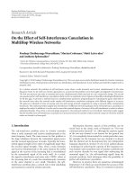
Fig. 1. Block diagram of MIMO E-SDM system
DSP Development KIT using Verilog HDL. We
Consider a MIMO E-SDM system with NTX
use HDL description in the whole system because
antennas at TX and NRX antennas at RX, as
we want an executable functional specification.
shown in Fig. 1. When MIMO CSI is available at
Besides, the executable models can be tested and
the TX, orthogonal transmit eigenbeams can be
refined
In
formed between the TX and the RX. Eigenbeams
addition, HDL description is the first step to build
are obtained from eigenvalue decomposition of
during
implementation
process.
an implementation directly from a behavioral
Trang 80
TAẽP CH PHAT TRIEN KH&CN, TAP 17, SO K2- 2014
matrix HHH, where H denotes as the MIMO
signal-to-noise power ratio (SNR) of the kth
channel matrix as following:
substream is given by k Pk Ps / . This indicates
h11
h21
H =
M
hN 1
RX
2
h12
h1NTX
h22
h2 NTX
M
hij
hN RX 2
M
hN RX NTX
,
that the quality of each substream is different.
(1)
Therefore, the channel capacity and BER
performance can be improved by adaptively
assigning the data rate and transmitting power [7,
At the TX side, an input stream is divided
into K substreams (K min(NRX, NTX)). Then,
signals before transmission are driven by a
transmit weight matrix WTX to form orthogonal
transmit beams and control power allocation. At
the RX side, received signals are detected by a
receive weight matrix WRX. The optimal WTX and
8].
3. DESIGN AND IMPLEMENTATION OF
MIMO E-SDM SYSTEMS
The block diagram of our design and
implementation of a 2x2 MIMO E-SDM system
on FPGA hardware is shown in Fig. 2. For the
case of 2x3 system, it
will be designed and
implemented similarly.
WRX are determined according to [7, 8] as
WTX = U P ,
(2)
WRX = U H H H ,
(3)
where U is obtained by the eigenvalue
Fig. 2. Design of a 2x2 MIMO E-SDM system
decomposition as
H H = UU ,
(4)
3.1. Transmitter side
In the TX side, we need to estimate CSI
= diag ( 1 , 2 ,..., K ),
(5)
matrix H fedback from the RX, and then
H
H
where 1 2... K>0 are positive
eigenvalues of HHH. The columns of U are the
eigenvectors corresponding to those positive
eigenvalues,
and
P = diag ( P1 , P2 ,..., PK ) is
determine the eigenvalue and eigenvector. Based
on these values, transmit data resources and
power allocation are calculated. The TX also
the
consists of other modules such as data generator,
transmit power matrix.
The detected signals in an ideal E-SDM
digital modulations, adding sending choice,
system are given by
transmitting, as shown in Fig. 3.
y(t ) = Ps(t ) + W RX n(t ),
adding
training
symbols,
normalizing
and
(6)
where s(t) is a transmit signal vector and n(t)
is AWGN noise at RX. The result from (6) shows
that the ESDM technique transforms the MIMO
channel into K orthogonal subchannels. The
Trang 81
SCIENCE & TECHNOLOGY DEVELOPMENT, Vol 17, No.K2- 2014
In the E-SDM technique, some calculations
will give very small values. So, we need to use
floating-point to meet the goal of the system. But
using floating-point will make the hardware cost
be larger than fixed-point. Therefore, we need to
use both fixed-point and floating-point in the
system.
The most critical part in the system is
Fig. 3. Transmitter block diagram
The Modulation module shown in Fig.4 uses
4QAM or 16QAM modulation which depends on
the input ‘choice’. It will be one block 16QAM if
the value of ‘choice’ is zero, and be two blocks
4QAM if the value is one.
Calculating power levels and choice values
module. In this one, we use floating-point for all
calculations because of its wide range. The
module has three main parts: calculating power,
calculating error-bit probability and deciding to
get choice which indicates we need 4QAM or
16QAM modulation. The design is based on
results shown in [7]
Fig. 4. Modulation module
Each of the signals Out1 and Out2 includes
two parts: in-phase (I) and Quadrature (Q)
components and is stored in a Look-up table
(LUT).
Fig 6. Calculating Power and getting choice
Choice values and training symbols need to
be transmitted to RX in order to be able to detect
Supposing CSI matrix H is already known,
correct transmitted data sub-streams. ‘Choice’
we calculate matrix HHH and then determine
values is modulated by BPSK and added to the top
eigenvalues and eigenvectors of the matrix, as
of the first data stream. The preamble training
shown in Fig. 5. In this module, we use fix-point
symbols are added into the original data for
10.22 to do all the calculations. Obtained
channel estimation at the receiver, as shown in
eigenvalues will be converted to single floating-
Fig.7. Here we use 8 orthogonal Hadamard bits for
point by module fixed-point to floating-point.
CSI estimation.
Fig 5. Calculating eigenvalue and eigenvector
Trang 82
Fig 7. Sending choice and training symbol module
TAẽP CH PHAT TRIEN KH&CN, TAP 17, SO K2- 2014
3.2. Receiver side
Fig. 10. Getting choice and demodulating module
After getting the choice value, based on it,
received signals will be demodulated correctly and
get transmitted data.
Fig 8. Receiver Side
training symbols Rx, channel estimation Rx,
4. IMPLEMENTED RESULTS AND
DISCUSSION
Based on the design and implementation of the
decoding, receive choice, choice decision, and
MIMO E-SDM systems, in the section, we will
demodulation, as shown in Fig. 8.
evaluate the bit-error rate (BER) of the systems,
The receiver consists of six main parts: add
In next module, we use Zero Forcing to detect
and compare it with simulation results in Matlab.
receive signals. Here we need two blocks: one
In the section, we also consider about the
when choice is zero, the number of data stream is
hardware consumptions for our system design.
one 16QAM stream, and two when choice is 1,
and the number of data streams is two QPSK
4.1. BER performance of designed systems
The BER performance of 2x2 and 2x3 MIMO
streams.
E-SDM systems is shown in this section. Here we
use zero-forcing weights to detect receive signals.
Both channel coding and without channel coding
are considered. In the figure, we also want to
compare the performance of MIMO E-SDM
systems with MIMO SDM systems based on both
computer
simulation
and
hardware
implementation results. The computer simulation
Fig. 9. Equalization module
At Fig.10, we can see the receiving choice
module. After decoding, the first data symbol
which is modulated with BPSK method contains
exactly the choice value we need. So that the
receiving choice module will start to demodulate
this symbol and get the choice back.
results are obtained by using Matlab software.
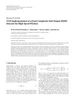
Firstly, a comparison of BER performance of
MIMO
E-SDM systems
simulation
using
between computer
Matlab
software
and
implementation results is shown in Fig. 10. Here,
we can see that both curves are almost the same.
The good match is because we use 32-bit floating
point to do all the calculations. This can conclude
Trang 83
SCIENCE & TECHNOLOGY DEVELOPMENT, Vol 17, No.K2- 2014
that our design and implementation of the systems
because of the optimal allocation of transmit data
are correctly.
resources and using orthogonal transmit beams in
Secondly, a comparison of BER performance
the E-SDM technique. When increasing the
between MIMO E-SDM and MIMO SDM
number of receive antennas, the BER performance
systems is considered in Fig. 11. It can be seen
of both MIMO E-SDM and SDM systems is
that MIMO E-SDM systems give much better
obtained better. This is due to higher diversity
performance than MIMO SDM ones. This is
gain.
Fig. 10. Comparison between computer simulation and
hardware implementation
Fig. 11. Hardware performance of MIMO SDM
4.2. Hardware Cost
In the section, we want to evaluate hardware
30%. Maximum speed of the system is 145.37
consumption in our system design and compare it
The detail hardware consumption of 2x3 MIMO
between MIMO E-SDM and MIMO SDM
E-SDM system is shown in Table 2. The system
systems.
occupies about 75% resource and the maximum
MHz.
Table 1 shows the detail hardware consumption
speed can go upto 142 MHz. It is easy to
of the design of 2x2 MIMO E-SDM system with
understand because the 2x3 system needs one
channel coding. The FPGA device used is Stratix
more antenna at receiver. That means it needs
III 3SL150F1152C2. It can be seen from Table 1
more hardware to control that antenna and to
that hardware resource can be free approximately
calculate in the equalizer module. In return, better
Trang 84
TAẽP CH PHAT TRIEN KH&CN, TAP 17, SO K2- 2014
BER performance is gotten as seen in Fig 11.
addition. Table 4 shows all mathematical functions
A comparison of the hardware consumption
we use in the systems and its number of pipeline
between MIMO E-SDM and MIMO SDM
stage. It can be seen that the E-SDM technique
systems is shown in Table 3. As we can see, the
needs many special kinds of mathematical
hardware cost of E-SDM system is two times
functions which are very hard to design on Verilog
larger than SDM. This is because of the much
HDL description.
higher calculation in the E-SDM technique. In
Table1. Hardware Consumptions of 2x2 MIMO E-SDM System
Consumption
Blocks
Speed
ALUTs
Logic Registers
(MHz)
Max: 113,600
Max: 113,600
1
208
588 (<1%)
780 (<1%)
Calculating H H
1
165
1,285 (1%)
2,071 (2%)
Get eigen-value
1
310
843 (<1%)
2,007 (2%)
Get eigen-vector
1
178
8,451 (7%)
9,636 (8%)
Get choice
1
418
95 (<1%)
127 (<1%)
Quantity
Normalize
H
Calculating Power
1
217
8,988 (8%)
11,468 (10%)
Calculating Probability
1
203
4182 (4%)
6557 (6%)
Channel Estimation
2
147
3,530 (3%)
7,505 (7%)
Sending choice
1
401
4 (<1%)
129 (<1%)
Add training symbol
4
243
15 (<1%)
74 (<1%)
Choice decide
1
420
128 (<1%)
194 (<1%)
SDM decoder 2 stream
1
162
22,519 (20%)
19,596 (17%)
SDM decoder 1 stream
1
169
9,232 (8%)
7,392 (7%)
Receiving choice
1
382
21 (<1%)
10 (<1%)
145
<55%
<69%
Total evaluation
Table2. Hardware Consumptions of 2x3 MIMO E-SDM System
Consumption
Blocks
Quantity
Speed
ALUTs
Logic Registers
(MHz)
Max: 113,600
Max: 113,600
Modulation
1
420
27 (<1%)
10 (<1%)
Normalize
1
208
588 (<1%)
780 (<1%)
Transmit
1
167
1,297 (1%)
1,824 (2%)
Calculating HHH
1
162
2,259 (2%)
4,279 4%)
Get eigen-value
1
310
843 (<1%)
2,007 (2%)
Trang 85
SCIENCE & TECHNOLOGY DEVELOPMENT, Vol 17, No.K2- 2014
Get eigen-vector
1
178
8,451 (7%)
9,636 (8%)
Get choice
1
418
95 (<1%)
127 (<1%)
Calculating Power
1
217.53
8,988 (8%)
11,468 (10%)
Calculating Probability
1
203
4182 (4%)
6557 (6%)
Channel Estimation
2
147
4,181 (4%)
9,520 (8%)
Add training symbol Tx
5
243
15 (<1%)
74 (<1%)
Choice decide
1
420
128 (<1%)
194 (<1%)
Demodulation
1
420
64 (<1%)
10 (<1%)
SDM decoder 2 stream
1
160
35,462 (31%)
24,212(21%)
SDM decoder 1 stream
1
165
10,526 (9%)
8,109 (7%)
Receiving choice
1
382
21 (<1%)
10 (<1%)
142
<70%
<75%
Total evaluation
Table3. Comparing Hardware Consumptions between MIMO Systems
Consumption
MIMO
Max Speed
ALUTs
Logic Registers
(MHz)
Max: 113,600
Max: 113,600
SDM 2x2
147
30%
31%
E-SDM 2x2
145
55%
69%
SDM 2x3
147
43%
36%
E-SDM 2x3
142
70%
75%
Table 4. Mathematical Functions for Real Numbers
Mathematical Function
5. CONCLUSION
MIMO systems
The number of Pipeline
Stages
Addition, Subtraction
8
Multiplication
4
Division
43
Square root
24
Logarithmic function
18
Exponential function
29
communications because of having maximum
E-SDM
channel capacity. In the paper, we have shown our
technique have been considered as a potential
own design and implementation of two MIMO E-
technology
SDM systems on hardware of FPGA-based DSP
Trang 86
for
applying
future
the
broadband
wireless
TAẽP CH PHAT TRIEN KH&CN, TAP 17, SO K2- 2014
Development Kit. Results of BER performance of
need to calculate TX weight matrix and estimate
the systems have shown that our design is good
RX weight matrix in each carrier. Therefore, it is
and reliability. We also compare the performance
very hard to control data flow. In addition, we
of MIMO E-SDM systems with MIMO SDM
need FFT and IFFT module in the MIMO-OFDM
systems. It has shown an outperformance of
E-SDM to prevent multi-paths. However, to
MIMO E-SDM systems. In the paper, we also
estimate Channel and RX weight matrix, the
calculate the consumption of FPGA elements in
system need both FFT and IFFT modules in each
our design. For 2x2 MIMO system, the hardware
side, transmitter and receiver. In [15], we design a
resource can be free approximately 30%.
module which can transform between FFT and
When compared with MIMO-OFDM E-SDM
system in [15], the hardware resource of Indoor
IFFT to decrease hardware resource.
ACKNOWLEDGEMENT:
is
research
is
MIMO E-SDM systems is much more smaller. 5%
supported by National Key Laboratory of Digital
free cost of 2x2 OFDM system is consequence of
Control and System Engineering (DCSELAB), HCMUT,
this complexity in this system. In this case, we
VNU-HCM under grant number 102.02-2011.23
Thc thi h thng MIMO E-SDM cho mng
khụng dõy tng lai trờn FPGA
Nguyn Trung Hiu
Bựi Hu Phỳ
DCSELAB, Trng i hc Bỏch Khoa, HQG-HCM
TểM TT:
Cỏc h thng Multiple-input multipleoutput (MIMO) ỏp dng k thut
Eigenbeam-Space Division Multiplexing
(E-SDM) cú th ủc xem nh cỏc h
thng MIMO ti u vỡ cú th mang li dung
lng kờnh cao nht v ủ tin cy cao.
Trong cỏc h thng ny, cỏc lung d liu
trc giao ủc truyn ủi gia hai bờn phỏt
v thu, v cỏc d liu truyn ủu vo s
ủc phõn b hp lý. Bờn cnh ủú, ti
phớa thu, mt b tỏch tớn hiu ủn gin s
ủc dựng ủ loi b nhiu gia cỏc
lung. Chớnh vỡ th, cỏc h thng MIMO ESDM ủc xem l cụng ngh tim tng
cho cỏc kt ni mng tc ủ cao trong
tng lai. Mc dự cú rt nhiu ti liu k
thut ủó c lng cỏc h thng ny trờn
phộp phõn tớch hc thuyt hay mụ phng,
nhng hu nh rt ớt bi bỏo mụ t vic
thit k h thng MIMO E-SDM trờn phn
Trang 87
SCIENCE & TECHNOLOGY DEVELOPMENT, Vol 17, No.K2- 2014
cứng. Mục ñích chính của bài báo này là
mô tả thiết kế và thực thi các hệ thống
MIMO E-SDM 2x2 và 2x3 trên kit phát triển
của Altera bằng cách dùng ngôn ngữ thiết
kế phần cứng Verilog HDL. Lỗi bit của hệ
thống và ñộ tiêu tốn tài nguyên của hệ
thống cũng ñược ñưa ra ñể cho thấy tính
tin cậy của các thiết kế này.
T khóa: MIMO, E-SDM, ZF, FPGA, hardware design.
REFERENCES
[1].
R. Prasad and L. Muoz, “WLANs and
WPANs towards 4G Wireless,” Artech
House, 2003.
MIMO channel,” IEICE Trans. Commun.,
vol. E88-B, no. 5, pp. 1843–1851, May
2005.
[2].
J. G. Andrews, A. Ghosh, and R.
Muhamed, “Fundamentals of WiMAX:
Understanding
Broadband
Wireless
Networking,” Prentice Hall, 2007.
[9]. H. Nishimoto, Y. Ogawa, T. Nishimura,
and T. Ohgane, “MIMO E-SDM
transmission performance in an actual
indoor environment,” IEICE Trans.
Commun., vol. E90-B, no. 6, pp. 1474–
1486, Jun. 2007.
E. Dahlman, S. Parkvall, J. Sk¨old, and P.
Beming, “3G Evolution: HSPA and LTE
for Mobile Broadband,” Elservier, 2007.
[10]. G. Labrun, J. Gao, and M. Faulkner,
[4].
E. Telatar, “Capacity of multi-antenna
Gaussian channels,”European Transaction
on Telecommunications, vol. 10, no. 6, pp.
585–589, Nov./Dec. 1999.
“MIMO transmission over a time-varying
channel using SVD,” IEEE Trans. Wireless
Commun., vol. 4, no. 2, pp. 757–764, Mar.
2005.
[5].
D. Gesbert, M. Shafi, D. S. Shiu, P. Smith,
and A. Naguib, “From the theory to
practice: An overview of MIMO spacetime
coded wireless systems,” IEEE J. Sel.
Areas Commun., vol. 21, no. 2, pp. 281–
302, April 2003.
[11]. S. H. Ting, K. Sakaguchi, and K. Araki, “A
[3].
[6].
[7].
[8].
J. Paulraj, D. A. Gore, R. U. Nabar, and H.
B¨olcskei, “An overview of MIMO
communications—A key to gigabit
wireless,” Proc. IEEE, vol. 92, no. 2, pp.
198–218, Feb. 2004.
K. Miyashita, T. Nishimura, T. Ohgane, Y.
Ogawa, Y. Takatori, and K. Cho, “High
data-rate transmission with eigenbeamspace division multiplexing (E-SDM) in a
MIMO channel,” Proc. IEEE VTC 2002Fall, vol. 3, pp. 1302–1306, Sept. 2002.
T. Ohgane, T. Nishimura, and Y. Ogawa,
“Applications
of
space
division
multiplexing and those performance in a
Trang 88
robust and low complexity adaptive
algorithm
for
MIMO
eigenmode
transmission system with experimental
validation,”
IEEE
Trans.
Wireless
Commun., vol. 5, no. 7, pp. 1775–1784,
July 2006.
[12]. Takaya
Kaji, Shingo Yoshizawa, and
Yoshikazu Miyanga, “Development of an
ASIP-Based Singular Value Decomposition
Processor in SVD-MIMO Systems,”
International Symposium on Intelligent
Signal Processing and Communications
Systems (ISPACS), pp. 1-5, Dec. 2011.
[13]. Hiroki Iwaizumi, Shingo Yoshizawa, and
Yoshikazu Miyanga, “A New High-Speed
and Low-Power LSI Design of SVDMIMO-OFDM Systems,” International
Symposium on Communications and
TAẽP CH PHAT TRIEN KH&CN, TAP 17, SO K2- 2014
Information Technologies (ISCIT), pp.
204-209, Oct. 2012.
[14]. Nguyen Trung Hieu, Bui Huu Phu, Tran
Van Tho, Vu Dinh Thanh, and Nguyen
Huu Phuong, Hardware Design and
Implementation of MIMO EigenbeamSpace Division Multiplexing Systems for
Future
Wireless
Communications
Networks,
The 2013 International
Conference on Advanced Technologies for
Communications (ATC'13).
[15]. Nguyen Trung Hieu,
Bui Huu Phu, Vu
Dinh Thanh, and Yasutaka Ogawa, FPGA
Implementation
of
MIMO
OFDM
Eigenbeam-Space Division Multiplexing
Systems
for
Future
Wireless
Communications Networks, 2013 78th
IEEE Vehicular Technology Conference
(VTC Fall).
Trang 89