A combination method of theory and experiment in determination of machine tool dynamic structure parameters
Bạn đang xem bản rút gọn của tài liệu. Xem và tải ngay bản đầy đủ của tài liệu tại đây (984.64 KB, 5 trang )
KHOA HỌC CÔNG NGHỆ
A COMBINATION METHOD OF THEORY AND EXPERIMENT
IN DETERMINATION OF MACHINE-TOOL DYNAMIC
STRUCTURE PARAMETERS
PHƯƠNG PHÁP KẾT HỢP LÝ THUYẾT VÀ THỰC NGHIỆM TRONG XÁC ĐỊNH CÁC THÔNG SỐ ĐỘNG LỰC HỌC
CỦA HỆ DAO ĐỘNG MÁY - CÔNG CỤ
Nguyen Nhu Tung1,*, Hoang Van Nam2,
Do Anh Tuan3, Nguyen Huu Hung4
ABSTRACT
In this paper, a combination method of the theory and experiment in
determination of dynamic parameters of machine-tool system was proposed. By
experimental research, the data of action force and the vibrations was collected
in time domain. By the theoretical research, using Fourier Transform, the data in
time domain was transformed and analysed in frequency domain. And then, the
parameters of the machine-tool dynamic structure were determined. The
proposed method was verified by the comparison of the calculated results and
the analysed results from analysis software.
Keywords: Dynamic parameters, vibration, machine-tool dynamic.
TÓM TẮT
Trong nghiên cứu này, một phương pháp kết hợp giữ lý thuyết và thực
nghiệm trong xác định thông số hệ dao động của hệ thống máy - công cụ được
đề xuất và thử nghiệm. Thông qua nghiên cứu thực nghiệm, dữ liệu về lực tác
động và dao động sinh ra được ghi lại trong miền thời gian. Bằng mô hình lý
thuyết với phép biến đổi Fourier, dữ liệu trong miền thời gian được biến đổi và
phân tích trong miền tần số. Từ đó, thông số của hệ thống dao động máy - công
cụ được tính toán, xác định. Phương pháp đề xuất đã được kiểm tra thông qua
việc so sánh kết quả tính toán với kết quả phân tích từ phần mềm.
Từ khóa: Thông số động lực học, dao động, hệ thống máy - công cụ.
1
Faculty of Mechanical Engineering, Hanoi University of Industry
Center of Mechanical Engineering, Hanoi University of Industry
3
Hung Yen University of Technology and Education
4
Hung Vuong University
*
Email:
Received:12 January2019
Revised: 6 May 2019
Accepted:10 June 2019
2
1. INTRODUCTION
During machine operations, the machine tool
experiences vibrations. The unbalance in turning and
boring, nonsymmetric teeth in drilling can produce
periodically varying cutting forces. In the milling process,
44 Tạp chí KHOA HỌC & CÔNG NGHỆ ● Số 52.2019
the tool, workpiece, and machine tool structures are
subject to periodic vibrations due to the intermittent
engagement of tool teeth and periodically varying milling
forces. The forced vibrations can simply be solved by
applying the predicted cutting forces on the transfer
function of the dynamic structure by using the solution of
ordinary differential equations in the time domain.
The fundamentals of vibration were explained,
including free vibration system and force vibration system.
These fundamentals were applied in solving the vibrations
in milling machining process. CUTPRO software and its
devices was proposed to determine the machine tool
dynamic structure. By using this measurement system, the
dynamic structure of milling machine tool systems can be
investigated and analysed. The experiments were
conducted to determine the machine tool dynamic
structure in machine-tool systems [1].
The phenomenon of vibration is an inextricable part of
any machining process and modern machine shops are well
aware of its detrimental effects. The machine tool vibration
can destabilize a machining process and in extreme situation
lead to chatter with severe implications for quality, tool life
and process capability. The vibration plays an important role
in limiting the afore-mentioned productivity parameters.
Reducing the vibration for a stable machining process may
reduce the number of time consuming operations, etc., to
obtain the desired surface finish and consequently reducing
the machining lead time [2].
There are both forced and self-excited vibrations of
machine tool in machining processes. However, the selfexcited vibration is the most detrimental for the safety and
quality of machining operations [2]. During machining, the
machine tool vibrations play an important role in hindering
productivity. The poor finished surface and damage of
spindle bearing may be caused by excessive vibrations [2, 3,
4]. Vibrations are very important in machining processes; so,
investigating and controlling the machine tool vibrations is
necessary in the improvement of machining quality.
SCIENCE TECHNOLOGY
This study focuses only on the application of theory and
experiment mothed in the investigation of machine-tool
dynamic structure. By this proposed method machine-tool
dynamic structure parameters such as nature frequency,
mass (m), spring (k), and damping (c) in x and y directions
were determined.
ℒ(ẍ + 2ζω ẋ + ω x) = ℒ
(3)
⟹ s x(s) − sx(0) − x , (0) + 2ζω sx(s) − 2ζω x(0) +
ω x(s) =
F(s)
(4)
⟹ (s + 2ζω s + ω )x(s) − (s + 2ζω )x(0) − x
F(s)
2. THEORETICAL OF MACHINE-TOOL DYNAMIC STRUCTURE
2.1. Theoretical of Forced-Vibration System
A simple structure with a single-degree of freedom
(SDOF) system can be modelled by a combination of mass
(m), spring (k), and damping (c) elements as shown in Fig. 1.
When an external force F(t) is exerted on the structure, its
motion is described by Eq. (1) and Eq. (2), [1, 2].
F(t)
, (0)
=
(5)
The system’s general response, the vibrations of the
structure with a SDOF dynamics, can be expressed by Eq. (6).
x(s) =
F(s) +
(
) ( )
,( )
(6)
The frequency response function of the system is
represented by Eq. (7) by neglecting the effect of initial
conditions that will eventually disappear as transient
vibrations.
Φ(s) =
( )
( )
=
(7)
Assuming that the external force is harmonic (it can be
represented by sin or cosine function or their
combinations). The forced vibration system can be
rewritten by Eq. (8).
ẍ + 2ζω ẋ + ω x =
Fig. 1. Vibration system
mẍ + cẋ + kx = F(t)
or
ẍ + 2ζω ẋ + ω x =
(1)
F(t)
(2)
where ωn is the natural frequency and ζ is the damping
ratio of system, and x is displacement of system in x
direction.
If the system receives a hammer blow for a very short
duration, or when it is at rest and statically deviates from its
equilibrium, the system experiences free vibrations. This
means no external forces (outside forces), F(t) = 0, but
only internal force controlled the motion. The internal
forces are forces within the system including the force of
inertia (mẍ ), the damping force (cẋ , (if c > 0)), and the
spring force (kx), a restoring force [1, 2].
2.2. Fundamentals of Forced Vibrations and frequency
response function (FRF)
When an external force F(t) is not equal to zero,
F(t) ≠ 0, the system experiences forced vibrations. When a
constant force F(t) = F0 is applied to the structure, the
system experiences a short-lived free or transient vibration
and then stabilizes at a static deflection xst = F0/k.
The general response of the structure can be evaluated
by solving the differential equation of the motion. The
Laplace transform of the equation of motion with initial
displacement x(0) and vibration velocity x’(0) under
externally applied force F(t) is expressed in Eq. (3) to
Eq. (5), [2].
F sin(ωt)
(8)
where ω is the frequency of external force F(t).
The system experiences forced vibrations at the same
frequency ω of the external force, but with the time or
phase delay (ϕ). It is assumed that the transient vibrations
caused by initial loading have diminished and the system is
at steady-state operation. Then the motion can be
rewritten by Eq. (9).
x(t) = Xsin(ωt + ϕ)
(9)
where X is the amplitude of vibration.
Using the complex harmonic functions of external force
and vibration, the harmonic force and the corresponding
harmonic response can be expressed by Eq. (10).
F(t) = F sin(ωt) = F e
(10)
)
x(t) = X sin(ωt + ϕ) = Xe (
The integration of motion is expressed by Eq. (11).
)
ẋ (t) = jωXe (
⟹
(11)
)
ẍ (t) = −ω Xe (
Substituting ẋ (t) and ẍ (t) into Eq. (8), the forced
vibration can be written by Eq. (12).
)
)
)
−ω Xe (
+ 2ζω jωXe (
+ ω Xe (
=
F e
(12)
⟹ (ω − ω + 2ζω jω)Xe (
)
⟹ (ω − ω + 2ζω jω)e Xe
=
=
F e
F e
(13)
(14)
so,
⟹ (ω − ω + 2ζω jω)Xe
=
F e
(15)
The frequency response function (FRF) of the system
can be expressed by Eq. (16).
Số 52.2019 ● Tạp chí KHOA HỌC & CÔNG NGHỆ 45
KHOA HỌC CÔNG NGHỆ
Φ(jω) =
(
)
(
)
=
(16)
The excitation to natural frequency ratio is r = ω/ωn. So,
the FRF can be expressed by Eq. (17) and Eq. (18).
Φ(jω) = .
The simple dynamic structure modal of the machinetool dynamic structure is described in Fig. 2. This system
can be modelled by a combination of mass (m), spring (k),
and damping (c) elements in x and y directions.
(17)
Φ(jω) = . (
(18)
)
The resulting amplitude (Gain) and phase of the
harmonic vibration are expressed by Eq. (19) to Eq. (20).
|Φ(jω)| =
(
)
(
)
ϕ = tan
(jω) = tan
= .
(
)
(
(19)
)
(20)
The FRF (Φ(jω)) can be separated into real (G(ω)) and
) as in Eq. (21) and
imaginary H(ω)) parts of (e (
Eq. (23).
G(ω) =
)
[(
H(ω) =
)
[(
(
(21)
) ]
(
) ]
or
Φ(jω) = G(ω) + jH(ω)
(23)
2.3. Determination of machine-tool dynamic structure
from FRF
When the input and the natural frequency of the forced
vibration system are the same (ω = ω ), the amplitude of
the vibration becomes larger and larger. Practically, the
systems with very little damping may undergo large
vibrations that can destroy the system. This phenomenon is
called resonance. With the frequency response function,
when the input force frequency is equal to the natural
frequency of vibration system, the real part of FRF is equal
to zero, and the imaginary part of FRF is equal to , or
(H(ω ) =
). And so, the natural frequency of a vibration
system (dynamic structure) can be determined at points
that the real part of FRF is equal to zero.
The maximum magnitude of FRF occurs at
ω = ω 1 − 2ζ . And the real part G(ωn) of FRF has two
extrema at frequency ω and ω as in Eq. (25).
ω =ω
ω =ω
1 − 2ζ ⟶ G
1 + 2ζ ⟶ G
=
=−
(
)
(
(24)
)
so, the damping ratio can be determined by Eq. (25), [2].
=
Fy
(22)
⟹ ζ=
(25)
Finally, the modal stiffness (k), the modal mass (m), and
the modal damping constant can be calculated by Eq. (26).
⎧ k=
( )
⎪
m=
⎨
⎪
⎩c = 2ζ√km
46 Tạp chí KHOA HỌC & CÔNG NGHỆ ● Số 52.2019
(26)
Fx
Fig. 2. Machine tool dynamic structure modal
Milling process is a dynamic process; so, by the effect of
machine-tool dynamic structure, the machine-tool
vibrations in x and y directions were calculated by Eq. (27),
[5-9].
m ẍ (t) + c ẋ (t) + k x = F (t)
(27)
m ÿ (t) + c ẏ (t) + k y = F (t)
Where: x, (mx), (kx), (cx), Fx(t) are the displacement, mass,
stiffness, damping ratio, and external force in x direction.
And, y, (my), (ky), (cy), Fy(t) are the displacement, mass,
stiffness, damping ratio, and external force in y direction.
By analysis of the Frequency Response Function of each
forced vibration system (x and y directions), the parameters
of machine-tool dynamic structure such as natural
frequency, modal stiffness, damping ratio, modal mass are
determined.
3. EXPERIMENTAL METHOD
The setup of the experiments in this paper includes tool,
CNC machine, FRF measurement. The description of the
setup is as the followings:
3.1. Tool, and CNC machine
In order to investigate of machine-tool dynamic
structure, the tool and machine were chosen as follows.
Tool: a new carbide flat-end mill with number of flutes
N = 2, a helix angle β = 300, a rake angle αr = 50, and a
diameter of 10mm. The experiments were performed at a
three-axis vertical machining center (DECKEL MAHO DMC70V hi-dyn).
SCIENCE TECHNOLOGY
3.2. Setup for determination of Frequency Response
Function
In order to determine the frequency response function
and the dynamic structure of machine-tool, an integrated
device system that consisted of the acceleration sensor
(ENDEVCO-25B-10668), hammer (KISTLER-9722A2000),
signal processing box (NI 9234), and a PC was used. The
detail setting of the measurement experiment is illustrated
in Fig. 3. The experiments were performed with the
assistance of CUTPROTM software to measure the force and
response displacement, [10].
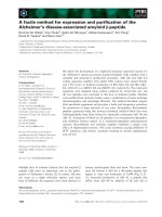
Fig. 4. The force and response displacement in X and Y directions
The signal of hammer force and the displacement values
obtained from the force and displacement sensors are
shown in the time domain, as shown in Fig. 4. It seems that
by Tapper test, in each direction (x or y direction), the impact
force was the single peak force. Besides, in each direction,
the response displacement decreased from maximum value
to zero. So, these are damped oscillation systems. The tapper
test results can be transformed form time domain to
frequency domain to determine the frequency response
function (FRF) of machine-tool dynamic structure.
4.2. Determination of Frequency Response Function (FRF)
Fig. 3. Setup of FRF measurement (Tap testing) [10]
a. Tool; b. Acceleration sensor; c. Force sensor; d. Signal processing box;
e. PC and CUTPROTM software
4. RESULTS AND DISCUSSIONS
4.1. Force and Response Displacement in Tapper test
Fig. 5. The real part and imaginary part of FRF in X and Y directions
Số 52.2019 ● Tạp chí KHOA HỌC & CÔNG NGHỆ 47
KHOA HỌC CÔNG NGHỆ
In this study, Fourier transform was use to transform the
measured results of the force and response displacement
from time domain to frequency domain. The FRF was
determined by Eq. (16) that the FRF was separated into two
parts (dash line): the real part and the imaginary part as,
shown in Fig. 5 for both x and y directions. The analysed
results of FRF was compared with the analysed results of
CUTPRO software (solid line) as described in Fig. 5. This
figure is shown that the analysed results were quite close to
the results of CUTPRO software in both x and y directions.
So, the proposed method in this study can be used the
determine the frequency response function of a machinetool dynamic structure.
part. The analysed results of FRF were quite close to the
results from CUTPRO software. So, the proposed method in
this study can be used the determine the frequency
response function of a machine-tool dynamic structure.
3. The calculated results of machine-tool dynamic
structure parameters between proposed method and
CUTPRO software are quite close together. The difference
of two methods is about 7.6 %. So, the proposed method in
this study can be used as a convenient method to
determine the machine-tool dynamic structure parameters.
4.3. Determination of machine-tool dynamic structure
Using the determined results of the frequency response
function (FRF) as expressed in Section 4.2, the machine-tool
dynamic parameter such as nature frequency (ωn), mass
(m), spring (k), and damping (c) were calculated and listed
in Table 1. The calculated results of machine-tool dynamic
structure parameter were compared with the analysed
results of CUTPRO software. The calculated results between
proposed method and CUTPRO software are quite close
together. The average difference of two methods is about
12.4 %.
Table 1. Machine-tool dynamic structure parameters
REFERENCES
[1]. Kreyszig, E., 2010. Advanced engineering mathematics. John Wiley &
Sons.
[2]. Altintas, Y., 2012. Manufacturing automation: metal cutting mechanics,
machine tool vibrations, and CNC design. Cambridge university press.
[3]. Hashimoto, M., Marui, E., & Kato, S., 1996. Experimental research on
cutting force variation during regenerative chatter vibration in a plain milling
operation. International Journal of Machine Tools and Manufacture, 36(10),
1073-1092.
[4]. Toh, C. K., 2004. Vibration analysis in high speed rough and finish milling
hardened steel. Journal of Sound and Vibration, 278(1), 101-115.
[5]. Budak, E., 2006. Analytical models for high performance milling. Part II:
Process dynamics and stability. International Journal of Machine Tools and
Manufacture, 46(12), 1489-1499.
[6]. Nguyen, N. T., Kao, Y. C., Huang, S. C., and Chen, M. S., 2015. A
prediction method of dynamic cutting force in the milling process of S45C by flatend mill cutter. CRC Press/Balkema (Taylor & Francis Group).
[7]. Moradi, H., Vossoughi, G., & Movahhedy, M. R., 2013. Experimental
dynamic modelling of peripheral milling with process damping, structural and
cutting force nonlinearities. Journal of Sound and Vibration, 332(19), 4709-4731.
[8]. Govekar, E., Gradišek, J., Kalveram, M., Insperger, T., Weinert, K.,
Stépàn, G., & Grabec, I., 2005. On stability and dynamics of milling at small radial
immersion. CIRP Annals-Manufacturing Technology, 54(1), 357-362.
[9]. Balachandran, B., & Gilsinn, D., 2005. Non-linear oscillations of milling.
Mathematical and Computer Modelling of Dynamical Systems, 11(3), 273-290.
[10]. Manufacturing Automation Laboratories Inc. (MAL), 2003. MAL Inc.
User Manual for CUPRO software. Manufacturing Automation Laboratories Inc. All
rights reserved.
Direction Mode No.
ωn ω1 ω2 H(ωn)
[Hz] [Hz] [Hz] [m/N]
k
[N/m]
m
[kg]
Research
2776 2742 2832 -4.47E-06 0.016 6.91E+06 0.896
X direction CUTPRO
2772 2734 2832 -5.02E-06 0.018 5.64E+06 0.734
Different (%) 0.14 0.29 0.00 11.00 8.296 22.53 22.174
Research
2780 2724 2842 -4.18E-06 0.021 5.64E+06 0.730
Y direction CUTPRO
2778 2722 2836 -5.39E-06 0.021 4.52E+06 0.586
Different (%) 0.07 0.07 0.21 22.52 3.434 24.79 24.606
The obtained results showed that the machine-tool
dynamic structure parameters of the different directions
are different. Besides, in each direction, the machine-tool
dynamic structure parameters are quite close to each other
but not the same when determining by proposed method
and by CUTPRO software. So, the proposed method in this
study can be used as a convenient method to determine
the machine-tool dynamic structure parameters.
5. CONCLUSIONS
In this study, a combination method of theoretical and
experimental method was performed to investigate the
machine-tool dynamic structure. Depending on the
analysis of experimental results, the conclusions of this
study can be drawn as follows.
1. The tapper test results can be transformed form time
domain to frequency domain to determine the frequency
response function (FRF) of machine-tool dynamic structure.
2. In each x or y direction, the determined FRF was
separated into two parts: the real part and the imaginary
48 Tạp chí KHOA HỌC & CÔNG NGHỆ ● Số 52.2019
THÔNG TIN TÁC GIẢ
Nguyễn Như Tùng1,*, Hoàng Vân Nam2, Đỗ Anh Tuấn3,
Nguyễn Hữu Hùng4
1
Khoa Cơ khí, Trường Đại học Công nghiệp Hà Nội
2
Trung tâm Cơ khí, Trường Đại học Công nghiệp Hà Nội
3
Trường Đại học Sư phạm kỹ thuật Hưng Yên
4
Trường Đại học Hùng Vương