Studying the implementation of finite element models in the orthogonal cutting processes with uncoated tool and TiN, TiCN and Al2O3 coated tool
Bạn đang xem bản rút gọn của tài liệu. Xem và tải ngay bản đầy đủ của tài liệu tại đây (529.26 KB, 8 trang )
Journal of Science & Technology 130 (2018) 043-049
Studying the Implementation of Finite Element Models in the Orthogonal
Cutting Processes with Uncoated Tool and TiN, TiCN
and Al2O3 Coated Tool
Nguyen Kien Trung*, Truong Hoanh Son
Hanoi University of Science and Technology - No. 1, Dai Co Viet, Hai Ba Trung, Hanoi, Viet Nam
Received: June 18, 2018; Accepted: November 26, 2018
Abstract
The metal machining is the most popular process used in the machinery part manufacturing. Therefore,
machining process needs to be controlled by properly selecting of cutting condition, tool materials and
coating to obtain the best machining time, good surface finish and low machining cost at the same time. To
understand the effects of various cutting condition, tool and coating materials, it is useful to simulate the
machining process using finite element techniques. This paper presents the preliminary investigation on the
implementation of two dimensional finite element modeling (FEM) with two approaches, Lagrangian mesh
description and Arbitrary Eulerian-Lagrangian (ALE) mesh description, to simulate the stress and cutting
temperature in the orthogonal cutting processes. The influence of various tool and coating materials (TiN,
TiCN and Al2O3 carbide coated tool, Polycrystalline Diamond - PCD) is also studied in comparison with
uncoated tool. Titanium alloy Ti-6Al-4V and AISI 1045 steel is selected as work materials in these FEM
models. The results show that the FEM model with ALE approach are adequate to simulate the stress and
temperature distribution with a high accuracy while the FEM model with Lagrangian approach is capable in
simulate chip formation.
Keywords: Finite element modeling, Machining simulation, AISI 1045 steel, Ti-6Al-4V, Coating
1. Introduction*
The stress and temperature distribution are not
only commonly used criteria for the evaluation of
machinability but also play a very important role in
identifying not only the main tool wear mechanisms
but also chip formation in the cutting process. Both
mechanical wear and thermochemical wear (including
dissolution and diffusion wear) are functions of the
stress and temperature. On the other hand, the stress
and temperature distribution on the chip are
determined to explain the chip morphology and
geometry which mainly are influenced on the stress
and temperature distribution on the chip. The
temperature on the tool and chip can be obtained by
experimental techniques (thermocouple, infrared
camera, temperature indicating liquid, etc.). However,
these techniques only measure in-situ local
temperatures. In another aspect, the stress on the chip
and the tool is hardly obtained by experiment.
Therefore,
computer-aided
engineering
tools
especially Finite Element Analysis (FEA) software
was utilized to perform the simulation of both
temperature and stress on the tool and chip. Many
researchers have been using FEA simulation to study
machining processes. Ansys, AdvantEdge, Abaqus,
*
Corresponding author: Tel.: (+84) 904.999.422
Email:
Deform, ThirdWave and FORGE are popular types of
finite element software have been focused in the
simulation the cutting process of steels and other
alloys. A lot of research conducted with the Finite
Element Modelling (FEM) simulation on the cutting
processes for carbon steels, alloyed steels and other
alloys such as Titanium alloys, Nickel alloys have
been published. In general, the simulation results of
FEM show a good agreement with the experimental
data during the machining process. Borsos et al. [1]
studied a 2D orthogonal turning model of AISI 1045
steel with Abaqus. By the comparison of result from
the experiment and a simulation using Johnson-Cook
damage model, he proved that the tangential forces
obtained from simulation model are well adequate for
various cutting conditions. The average difference
between the tangential forces achieved in
experimental measurements and those from
computational analyses was about 23%. Arrazola et
al. [2] using 2D cutting model with FEA software
Abaqus/Explicit to understand the thermal
phenomena in the cutting process of AISI 4140 steel
with different tool geometries and tool coatings. He
found that experiment and simulation both showed
the temperatures on coated tools were less than those
on uncoated tool. The temperatures on workpiece
were higher than those on cutting tool. The tool
geometry had significant effects to cutting
temperatures. Wu et al. [3] conducted a simulation of
43
Journal of Science & Technology 130 (2018) 043-049
orthogonal cutting process of titanium alloy (Ti-6Al4V) using ABAQUS software. The parameters for
simulation were achieved by the compress
experiment. The results of the simulation model wellpresented cutting characteristic of the machining
process. The orthogonal cutting finite element model
showed adiabatic shear bands which is common
cutting mechanism of Ti6Al4V. A 3-dimensional
(3D) model was implemented in DEFORM 3DTM by
work of Klocke et al [4] in order to predict of chip
formation and chip breakage in turning AISI 1045
steel. The results from FEM model correlated well to
those in experiments.
The present paper outlines a preliminary
investigation to study the implementation of 2D FEM
with two approaches in orthogonal cutting model for
AISI 1045 steel and Ti-6Al-4V with carbide and PCD
tool respectively to obtain stress and cutting
temperature. Furthermore, in the model of AISI 1045
steel, the temperature and stress in cutting zone with
uncoated carbide tool (WC) are compared with those
with TiN, TiCN and Al2O3 single layer coating in
cutting process.
2. Simulation of machining using FEM
In industries, it is necessary to know if a new
product or new design is adequate in working. Any
possible failure and error in working condition are
inevitable to be predicted, analyzed and controlled. In
research, any new material also went through a lot of
experimentation and testing at different working
condition before applying in the industries. Therefore,
the simulation of product in working environment is
common used before testing in real process. Finite
element modeling is most well-known as a numerical
simulation method. FEM is an effective technique
which uses a discretize model equations for
engineering problems. It is a utilized platform for
researchers to investigate for complex problem.
Besides that, FEM can also provide relatively
accurate results without carrying a lot of experiments
which reduces cost and time. In machining process,
FEM is frequently used to improve cutting processes
which mainly included reducing cutting forces and
cutting temperature; improving cutting time and
surface finish by investigating various cutting
condition regraded to cutting speed, feed rate, depth
of cut, tool paths respected to workpiece material,
tool materials and tool geometry. In spite of few
limitations, the FEM permits to reduce the cost of
manufacturing in terms of selecting right cutting
condition; predicting chip formation, cutting forces
and the tool life; and saving money and time by
estimating physical phenomena in cutting simulation
which could be happen in the real machining process.
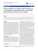
Fig. 1. The mesh and material description for 1D
problem in three approaches.
In order to assigning elements of the plastic
material flow in FEM modeling, there are three
descriptions of motion: (1) Arbitrary Eulerian (AE)
mesh description, (2) Lagrangian mesh description,
and (3) a combination of Arbitrary Eulerian and
Lagrangian (ALE) mesh description. The classical
Lagrangian and Eulerian technique are both
introduced by Boothroyd and Knight [5]. In AE
technique which is widely used in fluid dynamics, the
elements of the computational mesh are fixed in the
space and do not distort throughout a simulation and
the material is allowed to flow through elements. At
the beginning of calculation, the material is contained
within an element then passes through adjacent
elements as calculation proceed. In Lagrangian
technique which is mainly used in structural
mechanics, the material is attached to elements that
move with the flow. The material is contained and
remained within an element throughout the
simulation. Therefore, the mesh is tangle and
experiments large distortions in region with high
shear leading to numerical errors in the calculation. In
an attempt to combine the advantages and minimize
drawbacks of each individual formulation, ALE
method was first proposed and developed in 1960s. In
fact, there are classes of complex problem, for
example a problem consists both structural
components and fluids. The analysis of this type of
the problems is not easily obtained using either a
purely Eulerian or purely Lagrangian algorithms,
while ALE has been applied successfully. In ALE
approach, the movement of element is prescribed
independently to that of material particles. In ALE,
part of mesh may can be moved with the continuum
in normal Lagrangian description, part of mesh be
held fixed in Eulerian manner, and remainder will
move in an arbitrarily specified way, thereby a mesh
with large distortion can be handled with Lagrangian
algorithms while AE method can afford for a mesh
region needed higher resolution. The descriptions of
44
Journal of Science & Technology 130 (2018) 043-049
mesh and material in three formulations for 1D
problem are presented in Fig. 1.
2.1 Material constitutive modeling: Johnson and
Cook constitutive model
To modeling the material strength, the
phenomenological Johnson Cook (JC) model [6] is
mostly used. The flow stress constitutive equation for
the JC model is shown in Equation (1). The JC model
presents the flow stress () of a material as function
of the plastic strain , the strain rate
(s-1) and
temperature with the Johnson-Cook coefficients A, B,
C, n, m (A [MPa] - the initial yield strength (quasi
static yield strength) of the material at room
temperature and a strain rate of l/s; fitting constant B
[MPa] - the hardening modulus; C - the strain rate
sensitivity coefficient; m - thermal softening
coefficient; n - hardening coefficient; Tm [C] melting
temperature of material; and T0 [C] - room
temperature).
T − T0 (1)
n
( , , T ) = A + B ( ) 1 + C ln 1 −
0 Tm − T0
m
In order to run the simulation correctly, first and
foremost, the JC coefficients, the high stress and
strain rates with a high adiabatic shearing were
obtained from the experiment with Split Hopkinson
bar compression tests. The sets of these parameters of
example materials is given in Table 1. The set of JC
parameters from study of Borsos et al. [1] and Meyer
et al. [8] is used for the cutting simulation of AISI
1045 steel and Ti-6Al-4V, respectively in this study.
Table 1. Johnson-Cooks plasticity coefficients for
AISI 1045 steel and Ti-6Al-4V
introduced anymore. The experimental studies show
that the failure behavior depends on both the loading
conditions and the material properties. The material
failure described by the Johnson-Cook criterion is
one of the most used models to describe ductile
failure in numerical simulation for metals with for
high strain-rate deformation only. The JC failure
model follows a cumulative damage law that the
failure is assumed to occur at physical criterion when
the damage parameter D exceeds 1. This is the
criterion for chip formation. The expression of
damage parameter D in the JC ductile failure model is
introduced in the Equation (2) with
and
are
the equivalent plastic strain at failure and the
increment of equivalent plastic strain. The strain at
failure,
is calculated by Equation (3) from
dimensionless stain rate
and non-dimension
pressure-deviatoric stress ratio, p/q, with D1 to D5 are
failure parameters (
- reference stain rate, p pressure stress, q - Misses stress). In the ALE
formulation, the JC dynamic failure model is used in
ABAQUS/Explicit. Table 2 presents the sets of JC
failure parameters for AISI 1045 steel in the FEM
cutting simulation on this work and other studies.
pl
D = pl
f
(2)
pl
p
T − T0 (3)
fpl = D1 + D2 exp D3 1 + D4 Ln
1 + D5
Tmelt − T0
q
0
Table 2. Johnson-Cook damage coefficients for the
analytical failure model for AISI 1045 steel
D1
D2
D3
D4
D5
0[s-1]
References
0.05 4.22
-2.73
0.0018 0.55
1
Borsos et al. [1]
Material AISI 1045 [1] AISI 1045 [7] AISI 1045[9] Ti6Al4V[8]
0.06 3.31
-1.96
0.0018 0.58
-
Duan et al. [9]
A [MPa]
B [MPa]
C
n
m
In this paper, Johnson and Cook constitutive
model is implemented in both FEM model A and B
while Johnson-Cook criterion is applied on FEM
model A to study chip formation as well as the effects
of different coating materials on carbide substrate in
an orthogonal cutting process of AISI 1045 steel.
−
553.1
600.8
0.0134
0.0234
1
1
553
600
0.234
0.0134
1
-
553
600
0.234
0.0134
1
0.001
862.5
331.2
0.012
0.34
0.8
-
T0 [C]
25
25
20
-
Tm [C]
1460
1460
1460
1650
2.2 Ductile damage model for chip fracture criterion
(chip formation)
The ductile failure behavior of a material is very
important in order to successfully simulate the chip
formation (the separation between chip and
workpiece) in a machining process with FEM. The
ductile damage (structural failure) of a material starts
to occur since the load-carrying capacity and
resistance to deformation of the material are not
3. Simulation setup and simulation data
3.1 Geometrical model and simulation parameters
This study used 2D orthogonal cutting model to
obtain the chip formation, the stress and temperature
profile in cutting. Two FEM simulation models were
used in this study:
FEM model A with Lagrangian approach is
applied for AISI 1045 steel with uncoated and single
layer coated carbide tool (TiN, Al2O3, and TiCN).
45
Journal of Science & Technology 130 (2018) 043-049
FEM model B with ALE method is used in
cutting process with Ti-6Al-4V with PCD tool.
coefficient. PCD is well-known tool material in
cutting of Ti alloys since they showed good wear
resistance to mechanical and chemical wear. The
mechanical parameters of work material and tool
materials used in the simulation are presented in
These tool material and coatings are currently
the most common tool coatings for machining of
casting and alloy steels due to high hardness, good
wear-resistant characteristics and low friction
Table 3. The both simulation is conducted with
feed rate of 0.127 mm/rev while cutting speed of 100
tool geometry with the rake angle of 7°, the clearance
÷ 500 m/min and feed rate of 0.2 mm/rev were used
angle of 0°. The cutting process on Ti-6Al-4V
for the simulation with AISI 1045.
simulated at cutting speed of 61 ÷ 121 m/min and
Table 3. Material parameters for work material and tool materials
Density [kg/m3]
Elastic [Pa]
Poisson’s ratio
Expansion
Coefficient [1/C]
Specific Heat
[J/kgC]
Thermal conductivity
[W/m.C]
Melting Temp. [C]
Reference Temp. [C]
AISI 1045 [1]
7800
2.00E+11
0.3
Ti6Al4V [10]
4420
1.14E+11
0.34
WC [11]
4940
4.50E+11
0.18
Al2O3 [11]
3780
3.40E+11
0.23
TiN [11]
5420
2.5E+11
0.25
TiCN [11] PCD[12]
4180
3520
3.55E+11 8E+11
0.2
0.3
1.15E-5
9E-5
7.7E-6
8.4E-6
9.35 E-6
8.0 E-6
2.26E-6
486
560000
565.15
1173
818.9
1120
600
49.8
6.7
30.9
8.75
23
32
520
1460
25
1620
25
2780
25
2072
25
2950
25
2930
25
-
3.2. Boundary conditions and element meshing
The FEM simulation model A was conducted
with three boundary conditions to evaluate cutting
stress and temperature. The cutting tool was allowed
to move in X-direction with cutting speed Vx from the
right to the left while its movement in Y-direction is
restrained. The workpiece was assumed to be fixed at
the bottom. The most part of the left side of
workpiece is constrained X-direction. Fig. 3
demonstrates for all boundary conditions used in this
study. In orthogonal cutting configuration, undeformed chip thickness that specified tool position is
equal to the feed rate. Tool is modeled with a coating
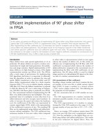
layer with thickness of 5 µm. In element meshing of
model A, a workpiece with two parts is developed to
facilitate for chip formation and to control the
contact. Part 1 is a region with fine elements to form
chip while the remainder is workpiece support which
consists of bigger elements as shown in Fig. 2. The
influence of mesh size in the simulation time is
significant. The simulations were performed with
element size ranged from 0.005 to 0.05 mm in order
to reduce computing time.
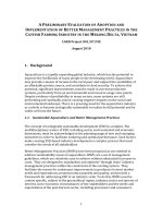
The 2D-FEM model B use Johnson-Cook model
and ALE formulation to obtain the temperature
profile. The chip formation in model B is only
generated by defined geometry because it uses ALE
mesh description. In this model, the tool was fixed
while the workpiece moved in X direction with
velocity Vx. The workpiece was also fixed at the
bottom as shown in Fig. 3.
Coating
layer
Tool
Part 1
WC
substrate
Part 2
Workpiece
Fig. 2. Boundary conditions and element meshing for
FEM model A in cutting process of AISI 1045.
Fig. 3. Boundary conditions and element meshing for
FEM model B in cutting process of Ti-6Al-4V.
46
Journal of Science & Technology 130 (2018) 043-049
Profile 2 (along
chip length)
Profile 3 (along
the rake face)
Profile 1
(crossed chip
thickness)
Fig. 4. The evaluated profiles of cutting stress and
cutting temperature.
4.1 The result of AISI 1045 cutting process with
FEM model A
In FEM model A with Lagrangian approach, the
nodes and elements on three profiles were deflected
due to the chip formation and chip breakage during
cutting simulation. Therefore, the cutting process was
simulated at the beginning with 0.5 mm of cutting
length to minimize deflection. Although the cutting
temperature at the beginning cutting stage was lower
than those at the steady state process, the setup is
valid to comparison purpose for cutting behavior of
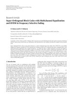
tool material and coatings. An example of chip
formation, distribution of cutting stress and cutting
temperature is demonstrated in Fig. 5 for cutting
process with TiCN coating. The results of the
simulation show that the simulation of the chip
geometry formation was reasonable acceptable. The
high stress was found at shear zone where the chip
formed. In all simulations with and without the
coating layers, the chip experienced higher cutting
temperatures than the tool which shows a good
agreement with the characteristics of real machining
process.
Fig. 7 compared cutting temperature along
Profile 3 in cutting process with uncoated tool and
coated tools at cutting speeds of 100 and 400 m/min.
In general, the higher cutting temperature and stress
on workpiece were obtained at the high cutting
speeds. Along Profiles 1 crossed the chip thickness,
the high temperature was obtained near the contact
zone for low cutting speeds, while high cutting speed
showed high temperatures near the top surface of the
chip. It can be declared that, at Profile 2 along chip
thickness, the highest temperature is occurred near
the tool tip which is common in machining of steels.
The high temperature at the tool tip would lead to
edge softening and fracturing off resulted in tool
failure at early stage. In comparison with other
researches, the results are relatively comparative with
the simulation and experimental cutting temperatures
reported in study of Fahad et al. [11] with
TiCN/Al2O3/TiN multi-coated tool. In his study, the
maximum cutting temperature is around 170 C at
cutting speeds of 314 m/min and feed rate of 0.16
mm/rev.
1.4e+3
100 m/min
200 m/min
400 m/min
1.2e+3
Mises stress (MPa)
In both FEM simulation models, the stress and
cutting temperature are plotted along three profiles.
Profile 1 is along chip thickness, Profile 2 is along
chip’s length 2, and Profile 3 is along the rake face of
the tool as shown in Fig. 4.
Fig. 7 represented temperature along these
profiles.
Al2O3
1.0e+3
8.0e+2
6.0e+2
4.0e+2
2.0e+2
0.0
0.1
0.2
0.3
0.4
Distance from the tool rake face (mm)
1.4e+3
100 m/min
200 m/min
400 m/min
1.2e+3
Mises stress (MPa)
4. Result and discussion
Al2O3
1.0e+3
8.0e+2
6.0e+2
4.0e+2
2.0e+2
0.0
0.1
0.2
0.3
0.4
0.5
0.6
0.7
Distance from the tool tip (mm)
Fig. 6. Stress on profile 1 (crossed chip thickness)
and profile 2 (along chip length) in cutting process of
AISI 1045 with the Al2O3 coating.
Fig. 5. The chip formation and temperature
distribution with FEM models A for AISI 1045.
Fig. 6 plotted the stress with Al2O3 coated tool
at along profile 1 and profile 2, while
In other view regarded to tool material and
coatings, at high cutting speeds (500 m/min), the
varied coatings showed slight difference in tool
temperatures. However, the effect of coating to
temperature on the rake face is more apparently at
low cutting speed (100 m/min) as shown in Fig. 8.
47
Journal of Science & Technology 130 (2018) 043-049
The Al2O3 had the lowest cutting temperatures along
the rake face. The highest temperatures were obtained
with uncoated tool and TiCN coating. High cutting
temperature contributed to significant effects to the
wear rate at rake face (crater wear) in which the
dissolution/diffusion wear was dominant at the high
temperature zone, while abrasive wear and adhesion
wear was minor. The reduction in tool hardness and
edge geometric stabilization which were also very
important in machining process was another
consequence of the high tool temperature.
Fig. 9. The chip formation and temperature
distribution with FEM models B for Ti-6Al-4V.
200
180
Fig. 10. Temperature on Profile 1(along tool rake
face) in cutting process of Ti-6Al-4V with PCD tool.
Temperature (oC)
160
140
120
100
Al2O3
80
100 m/min
200 m/min
400 m/min
60
40
0.0
0.1
0.2
0.3
0.4
0.5
Distance from the tool rake face (mm)
200
100 m/min
200 m/min
400 m/min
180
Temperature (oC)
160
Al2O3
140
120
100
80
Fig. 11. The effect of tool-chip friction coefficient in
cutting process of Ti-6Al-4V with PCD tool.
60
40
20
0
0.0
0.2
0.4
0.6
0.8
Distance from the tool tip (mm)
Fig. 7. Temperature on Profile 1 and Profile 2 in
cutting process of AISI 1045 with the Al2O3.
120
Al2O3
TiN
TiCN
Uncoated
Temperature (oC)
100
80
100 m/min
60
40
20
0
0.0
0.2
0.4
0.6
0.8
1.0
Distance from the tool tip (mm)
Fig. 8. Temperature on Profile 3 (along rake face) in
cutting process of AISI 1045 with varied coatings at
cutting speed of 100 m/min
4.2 The result of Ti-6Al-4V cutting process with
FEM model B
In case of FEM model B for cutting process of
Ti-6Al-4V, the temperature profiles on the chip along
the rake face and through the thickness of the chip
were the main interest. The highest cutting
temperature is happened near the tool tip (tool nose)
as shown in Fig. 9. This is opposite to those in cutting
of steels which was observed far from tool tip. Fig. 10
plotted temperature at Profile 3 with various cutting
speeds. The effects of cutting speed to cutting
temperature was more significant than those in case
of AISI 1045 cutting. Titanium alloy are classified as
difficulty-to-machine cause of their low thermal
conductivity leading very high temperate at cutting
zone. The simulation results are accepted in
comparison with experiment data. The research work
of Khanna et al. [13] on cutting of Titanium alloys at
feed rate of 0.15 mm/rev showed that cutting
temperatures are in the range of 600 C ÷ 800 C and
800 C ÷ 1000 C for cutting speeds of 40 m/min and
80 m/min. In addition, although the majority of heat
generated was from plastic deformation, the
simulation results proved that the friction has some
impact on the temperature profile as shown in Fig.
11. To determine a reasonable friction coefficient to
be used, a comparison of chip-tool contact length
48
Journal of Science & Technology 130 (2018) 043-049
between experiment data and those of simulation
model is needed to be carried out in future work.
5. Conclusion
In this work, two 2D FEM simulation models
are conducted with Abaqus software to study stress
and temperature distribution in orthogonal cutting
process The cutting process of AISI 1045 steel with
uncoated and single layer coated carbide tool (TiN,
Al2O3, and TiCN) is simulated with the model A by
Lagrangian approach while the cutting of Ti-6Al-4V
with PCD tool is conducted in the model B with ALE
method. The effect of Al2O3, TiN and TiCN coatings
on carbide tool in cutting process of AISI 1045 steel
and their differences were also studied. The result of
the both simulation models is acceptable in term of
predicting chip formation, stress and temperature
distribution. However, the findings of simulation
model need to be verified with the experimental
results for confirmation. From this investigation,
some of outcomes are:
The simulation of mechanical-thermal behavior
of cutting process is acceptable for both models. The
simulation of the chip geometry formation with FEM
model A is capable with a reasonable accuracy. The
limitation in chip formation of FEM model B makes
this approach only suitable for study the stress and
temperature distribution.
In comparison of cutting process of AISI 1045
steel and Ti-6Al-4V, the Titanium alloy is obtained
the highest temperatures closer to the tool tip than
those of the steel. This phenomenon is needed to be
aware to avoid fracturing of tool edge.
In comparison of different coatings in cutting
process of AISI 1045, the Al2O3 showed the highest
reduction in tool temperatures at low cutting speed in
comparison with TiN and TiCN coatings, although its
influence is not strong at high cutting speed.
With extra verification work, this study can be
developed as a useful reference for investigating
cutting conditions, tool materials, coating materials;
and explaining cutting properties of machining
process.
[2]
[3]
[4]
[5]
[6]
[7]
[8]
[9]
[10]
[11]
6. Acknowledgements
This study was conducted with financial support
from Hanoi University of Science and Technology
(HUST) under project number T2016-PC-062. The
School of Mechanical Engineering at HUST is also
gratefully acknowledged for providing guidance and
expertise.
[12]
[13]
Reference
[1] Borsos, Benjámin, András Csörgo, Anna Hidas, Bálint
Kotnyek, Antal Szabó, Attila Kossa, and Gábor
49
Stépán. "Two-Dimensional Finite Element Analysis of
Turning
Processes."
Periodica
Polytechnica.
Engineering. Mechanical Engineering 61, no. 1
(2017): 44.
Arrazola, P. J., I. Arriola, and M. A. Davies. "Analysis
of the influence of tool type, coatings, and
machinability on the thermal fields in orthogonal
machining of AISI 4140 steels." CIRP AnnalsManufacturing Technology 58, no. 1 (2009): 85-88.
Wu, Hong-bing, Chengguang Xu, Zhi-xin Jia, Xuechang Zhang, and Gang Liu. "Establishment of
constitutive model of titanium alloy Ti6Al4V and
validation of finite element." In Measuring
Technology
and
Mechatronics
Automation
(ICMTMA), 2010 International Conference on, vol. 2,
pp. 141-144. IEEE, 2010.
Klocke, Fritz, Dieter Lung, and Christoph Essig. "3D
FEM model for the prediction of chip breakage." In
Advanced Materials Research, vol. 223, pp. 142-151.
Trans Tech Publications, 2011.
Knight, Winston A., and Geoffrey Boothroyd.
Fundamentals of metal machining and machine tools.
Vol. 198. CRC Press, 2005.
Johnson, Gordon R., and William H. Cook. "A
constitutive model and data for metals subjected to
large strains, high strain rates and high temperatures."
In Proceedings of the 7th International Symposium on
Ballistics, vol. 21, no. 1, pp. 541-547. 1983.
Nasr, Mohamed NA. "Effects of sequential cuts on
residual stresses when orthogonal cutting steel AISI
1045." Procedia CIRP 31 (2015): 118-123.
Meyer, Hubert W., and David S. Kleponis. "Modeling
the high strain rate behavior of titanium undergoing
ballistic impact and penetration." International Journal
of Impact Engineering 26, no. 1 (2001): 509-521.
Duan, C. Z., T. Dou, Y. J. Cai, and Y. Y. Li. "Finite
element simulation and experiment of chip formation
process during high speed machining of AISI 1045
hardened steel." International Journal of Recent Trends
in Engineering 1, no. 5 (2009): 46-50.
Calamaz, Madalina, Dominique Coupard, and Franck
Girot. "A new material model for 2D numerical
simulation of serrated chip formation when machining
titanium alloy Ti–6Al–4V." International Journal of
Machine Tools and Manufacture 48, no. 3-4 (2008):
275-288.
Fahad, Muhammad, Paul T. Mativenga, and
Mohammad A. Sheikh. "A comparative study of
multilayer and functionally graded coated tools in
high-speed machining." The International Journal of
Advanced Manufacturing Technology 62, no. 1
(2012): 43-57.
Schindler, S., M. Zimmermann, J. C. Aurich, and P.
Steinmann. "Finite element model to calculate the
thermal expansions of the tool and the workpiece in
dry turning." Procedia CIRP 14 (2014): 535-540.
Khanna, N., and Sangwan, K. S. “Machinability
analysis of heat treated Ti64, Ti54M and Ti10. 2.3
titanium alloys.” International Journal of Precision
Engineering and Manufacturing, 14(5), (2013): 719724.
Journal of Science & Technology 130 (2018) 043-049
50