Network coding on cooperative relay networks
Bạn đang xem bản rút gọn của tài liệu. Xem và tải ngay bản đầy đủ của tài liệu tại đây (378.55 KB, 27 trang )
Viet Nam National University, Ha Noi
University of Engineering and Technology
Lam Sinh Cong
Network Coding
On Cooperative Relay Networks
Branch: Electronics and Telecommunications Technology
Major: Electronics Engineering
Code: 60 52 70
Master Thesis Summary
Ha Noi-2012
Contents
Abstract
1
1 Introduction
1
1.1
1.2
1.3
Introduction to cooperative relay networks . . . . . . . . . . . . . . . . . . .
1
1.1.1
The relay protocols . . . . . . . . . . . . . . . . . . . . . . . . . . . .
2
1.1.2
Advantages of Cooperative Diversity Relaying Networks . . . . . . .
2
Introduction to Network Coding . . . . . . . . . . . . . . . . . . . . . . . . .
2
1.2.1
Non-Binary and Binary Network Coding . . . . . . . . . . . . . . . .
3
1.2.2
Advantages of Network Coding . . . . . . . . . . . . . . . . . . . . .
3
1.2.3
Weaknesses of Network Coding . . . . . . . . . . . . . . . . . . . . .
3
Cooperative Diversity Relaying Networks using network coding . . . . . . . .
3
2 System models
5
2.1
Traditional Relay Multiple-Wireless Networks . . . . . . . . . . . . . . . . .
5
2.2
Single Relay Networks using Network Coding . . . . . . . . . . . . . . . . .
6
2.3
Multiple-Relay Networks using Network Coding . . . . . . . . . . . . . . . .
8
3 Outage Probability Calculations
9
3.1
Mutual Information . . . . . . . . . . . . . . . . . . . . . . . . . . . . . . . .
9
3.2
Outage Probability Definition . . . . . . . . . . . . . . . . . . . . . . . . . .
9
3.3
Outage Probability of Multiple-Relay Networks . . . . . . . . . . . . . . . .
11
3.3.1
Traditional Decode-and-Forward relaying . . . . . . . . . . . . . . . .
11
3.3.2
Selection Decode-and-Forward relaying . . . . . . . . . . . . . . . . .
12
3.4
Outage Probability of Single Relay Networks using Network coding . . . . .
12
3.5
Outage Probability of Multiple-Relay Networks using Network Coding . . . .
16
Conclusions and Future Works
19
i
Bibliography
19
ii
List of Figures
2.1
A traditional single relay network . . . . . . . . . . . . . . . . . . . . . . . .
6
2.2
A traditional multiple-relay network . . . . . . . . . . . . . . . . . . . . . . .
6
2.3
Network coding in single relay network . . . . . . . . . . . . . . . . . . . . .
7
2.4
Multiple-relay network using network coding . . . . . . . . . . . . . . . . . .
8
3.1
The direct link between the input and the output . . . . . . . . . . . . . . .
10
3.2
Outage probability of a direct link . . . . . . . . . . . . . . . . . . . . . . . .
11
3.3
Outage Probability of fixed and selection DF relay . . . . . . . . . . . . . . .
13
3.4
The degraded system model of a single relay network based on NC . . . . . .
13
3.5
The degraded system model of a single relay network based on NC . . . . . .
14
3.6
Outage probability of the single relay network with and without network coding 15
3.7
Link s1 r1 is in outage . . . . . . . . . . . . . . . . . . . . . . . . . . . . . . .
17
3.8
Outage probability of relay networks with different scenarios . . . . . . . . .
18
iii
Abstract
In communication, Cooperative Diversity Relaying refers to devices communicating with one
another with the help of relays in order to increase the performance of the network. However,
in one timeslot, the relay only transmits the signal of one source. Therefore, Network Coding is
introduced to improve the throughput of the network. Combining Cooperative Relay Network and
Network Coding should be studied to achieve significant benefits and overcome some weakness. In
this thesis, we consider the effect of Network Coding on Cooperative Relay Network. We propose
to use Selection Decode-and-Forward instead of Traditional Decode-and-Forward protocol at the
relay. We also use the instantaneous channel gains to calculate the outage probability of the proposal
system model.
The rest of the thesis is organized as follows. In Chapter II, the system model of a multiple-relay
network is described. The outage probability is calculated in Chapter III. Finally, the conclusions
and the future works are drawn in Section IV.
Chapter 1
Introduction
1.1
Introduction to cooperative relay networks
In recent years, MIMO (multi-input multi-output) technology based on spatial diversity and
spatial diversity has attracted attention in wireless communication because it greatly improves the
reliability, the throughput and the transmission rate without additional bandwidth nor requiring
higher transmitter power. However, this technique requires both the transmitter and the receiver
to have multi-antennas, and all channels must be independent. In practice, users do not often
achieve full-rank MIMO because they either do not have multiple-antennas installed on a small-size
devices, or the propagation environment cannot support MIMO, for example, there is not enough
scattering. Even if the users have enough antennas, full-rank MIMO is not guaranteed because the
links between several antenna elements are often correlated.
To overcome the limitations in diversity gain MIMO, a new communication paradigm which uses
an intermediate node to generate independent channel between the user and the base station was
introduced. The intermediate node often called relay node receives the signal transmitted from the
user and forward it to the base station. And this paradigm is called Cooperative Diversity Relaying
Network.
1
1.1.1
The relay protocols
A key aspect of the cooperative communication process is the processing of the signal received
from the source node carried out by the relay. These different processing schemes depend on the
protocols of the relays which can be generally categorized into fixed relaying schemes, selection
relaying protocol (adaptive relaying schemes) and incremental relaying protocol.
1.1.2
Advantages of Cooperative Diversity Relaying Networks
Cooperative Diversity Relaying refers to devices communicating with one another with the help
of relays in order to increase the performance of the network [3]. Thereby, the relay channel can be
considered as an auxiliary channel to the direct channel between the source and destination.
In Cooperative Diversity Relaying, the user can guarantee the maximum diversity which is equal
the number of the relays plus the direct link, i.e being the minimum cut at each source. It means
that the limitation of MIMO technique has been overcome.
However, in cooperative relay network, we are able to use one or more relays, but in one timeslot,
the relay only transmits the signal of one source.
1.2
Introduction to Network Coding
As discussed in the previous section, in a typical network, information is transmitted from the
source node to each destination node through a chain of intermediate nodes by a method known
as store-and-forward. In this method, the intermediate node only processes and transmits a unique
signal at one time without overlapping, thus slow down the through. In order to increase the
throughput of the network, network coding technique was introduced in [5] and then further developed in [6], as a new paradigm which exploits the characteristics of the broadcast communication
channel to combine several input signals into one output signal at the intermediate node.
2
1.2.1
Non-Binary and Binary Network Coding
In binary network coding, the intermediate node uses XOR operator to consolidate the received
messages transmitted form sources.
In non-binary network coding, each intermediate node uses a linear equation to combine the
inputs and the destination uses the system of linear equation to decode the received messages.
1.2.2
Advantages of Network Coding
Increasing throughput achieved by increasing the efficiency of packet transmission is the most
well-know benefit of network coding.
1.2.3
Weaknesses of Network Coding
The main issue of using network coding is that if a transmission error occurs, it could affect
the detecting and coding at the intermediate node, and the destination node could receive useless
information.
Besides, synchronization and transmission delay among the incoming data streams at the input
of the intermediate node or destination node are also significant issues that need to be considered
when network coding is applied. The transmitted data can not be recovered until all the necessary information is received. These are not big problems for non-real time services (e.g data and
voice transmission), but they are should be considered carefully for real time services (e.g video
transmission,...).
1.3
Cooperative Diversity Relaying Networks using network coding
The most common example of NC-based network model is two-source one-relay topology, as
shown in Figure 2.3. In this topology, two sources transmit their signals to the relay and the
destination using broadcast technique. Then, the relay combines its received signals into a unique
signal and sends it to destination. The traditional Decode-and-Forward (DF) protocol is often used
3
at the relay which decodes the messages from its input nodes before sending them to its output
nodes. Often, the links between the sources and relay are assumed to be error-free so that the relay
decodes the received messages successfully [3, 11–13]. In [14], taking into account of link errors, the
relay is assumed to perform DF without error checking and the network codes are designed for error
correction.
In this thesis, instead of using DF relaying as in [14], we propose to use selection DF relaying
at the relay. The selection DF relaying protocol is designed to overcome the shortcomings of
DF relaying when the measured SNR at the relay falls below a threshold such that the relay
becomes unable to decode the messages, the source simply continues its direct transmission to the
destination using repetition coding [15]. In addition, we use Maximum Ratio Combining (MRC)
at the destination. Finally, we analyze the performance of the proposed scheme in terms of outage
probability by using the instantaneous channel gains. The analysis is based on a newly developed
method for exact calculation of the outage probability [16].
4
Chapter 2
System models
2.1
Traditional Relay Multiple-Wireless Networks
In this section, we will discuss about end-to-end signal of the selection Decode-and-Forward
relay. Relaying is assumed to operate in the time division mode having two phases (two time slots):
the relay-receive phase and the relay-transmit phase.
The total received signal at the destination is given by equation (2.1) and (2.2)
or
√
0
xsi nsi d
ysi d Ps hsi d
=
+
√
yri d
Ps hri d
xri
nri d
0
(2.1)
√
0
ysi d Ps hsi d
xsi nsi d
=
+
√
ysi d
0
x si
nsi d
Ps hsi d
(2.2)
Equatio
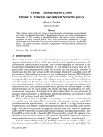
Now, we consider a wireless network system model using two sources-and-one relay, as show in
Figure 2.1. In this system model, the relay shares timeslot for both source S1 and S2 . Therefore, it
require 4 timeslots to complete a transmission process.
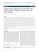
In order to increase the network’s throughput by reducing the number of timeslots, we increase
the number of relay. Figure 2.2 shows a relay network using two relays (R1 , R2 ) with selection-DF
protocol relaying information for two sources (S1 , S2 ) to the destination [18]. It is clear that it
requires at least 3 time slots in order to complete a transmission process.
5
(1) x1
S1
R
(2)x1
N4
(4)x2
S 2 (3)x
2
Figure 2.1: A traditional single relay network
x1
R1
S1
D
x2
S2
R2
Figure 2.2: A traditional multiple-relay network
In this thesis, we review the calculation of the cumulative distribution function (cdf) of instantaneous channel gains of various wireless links in a diversity relay network, which was published by
the author of this thesis and his co-author in [16, 19].
2.2
Single Relay Networks using Network Coding
Figure 2.3 shows a single relay network with two sources using network coding [20].
• In timeslot 1:
– S1 sends its signal x1 to both relay and destination by using broadcast mode.
6
S1
x1
hs1d
hs1r
hrd
R
x1 x2
hs2 r
S2
D
hs2d
x2
Figure 2.3: Network coding in single relay network
– The relay can or cannot decode x1 .
• In timeslot 2
– If R can not decode x1 , S1 repeats sending x1 to D, thus D receives x1 on 2hs1 d
– If R can decode x1 , S1 will do nothing in timeslot 2 and R store x1 in it and waits for x2
In the meantime
– S2 transmits its signal x2 to relay and destination using broadcast mode.
– R can or cannot decode x2
– If R cannot decode x2 , S2 repeats sending x2 to D, thus D receives x2 on 2hs2 d
• In timeslot 3
– If the relay is unable to decode neither x1 nor x2 , it must be silent.
– If the relay only decodes xi , it will forward xi to destination.
– If the relay decodes x1 and x2 , successfully, it combines x1 and x2 by using XOR operator
before sending it to the destination.
When all source-relay links are perfect, the destination decodes the received messages by using
algorithm:
x1 ⊕ x1 ⊕ x2 = x2
or
7
x2 ⊕ x1 ⊕ x2 = x1
Because of using less time slot than system model depicted in Figure 2.1, it indicate that system
model can improve the throughput of the networks. Comparing with the system model depicted in
figure 2.2, it cannot save any time slot, but we can save one relay.
2.3
Multiple-Relay Networks using Network Coding
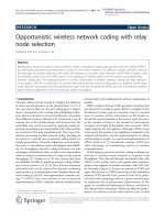
Figure 2.4 shows a multiple-relay network using coding in the cooperative relays, it is considered
as a technique to improve the robustness. The system model under analysis is given by the multipleaccess relay channel, where two source nodes, S1 and S2 , communicate with destination with the
help of two relays R1 and R2 . The notation used for this system and their operation are the same
S1
h s1d
x1
R1
R2
x2
hs2r2
S2
h r1 d
x1 x2
MRC
x1 x2
D
h r2 d
hs2d
Figure 2.4: Multiple-relay network using network coding
in Session 2.2 for relay R1 and R2 .
At destination, we use MRC to combine the signals from R1 and R2 in to a better signal of
higher SNR. I hope that this may improve the robustness of the network. Note that, if both relays
R1 and R2 are not able to decode the messages of source Si , Si repeats its transmission to the
destination by using repetition code.
In chapter 3, we will show that by using MRC, the performance of the network is increased.
8
Chapter 3
Outage Probability Calculations
3.1
Mutual Information
The instantaneous capacity of the system is given by the instantaneous mutual information
contained in the input-output vectors Xs and Yd for fixed channel realization matrix A, and it is
I(Xs ; Yd |A) = h(Yd ) − h(Yd |Xs )
= h(Yd ) − h(AXs |Xs ) − h(N )
(3.1)
1
ARXs A∗
log2 det(Im +
)
M +1
RN
(3.2)
Therefore [21]
I(Xs ; Yd |A) =
where M is the number of relays; and the covariance matrices of the input signal and the noise are,
respectively RXs = E{Xs Xs∗ } = Ps I and RN = E{N N ∗ } = N0 I
3.2
Outage Probability Definition
In this section, we define the outage probability of direct transmission between two nodes. The
received signal at the destination is given by
y[n] = x[n]h[n] + w[n]
9
Figure 3.1: The direct link between the input and the output
Where x[n], h[n] and w[n] are transmitted signal, channel gain, and Addition White Gaussian Noise
(AWGN), respectively. We assume that h is independent and identically distributed. Thus, the
maximum average information between the input and the output is given by using (3.2) with
M = 0, A = h, SN R = P/No :
I = log(1 + SN R|h|2 )
in which SN R is the received signal-noise ratio at the destination.
The outage event of the information rate for a given threshold Rth is defined as: I ≤ Rth and
equivalently [15]
|h|2 <
2Rth − 1
= µth
SN R
(3.3)
µth is called the channel power threshold.
Then the outage probability is expressed as:
Phout
(µth ) = P (|hij |2 < µth )
ij
(3.4)
For Rayleigh fading, |hij |2 is exponentially distributed, with the probability density function (pdf)
and cumulative density function (cdf) being respectively given by:
fhij (µ) =
1
µ
exp −
µij
µij
and Fhij (µ) = 1 − exp
−µ
µij
(3.5)
Then, the outage probability is written as follow by combing (3.4) and (3.5)
Phout
(µth ) = Fhij (µth ) = 1 − exp −
ij
10
µth
µij
(3.6)
Outage probability of one direct link
0
Outage Probability
10
−1
10
µij=1
µij=2
−2
10
µ =3
ij
−3
10
0
0.05
0.1
0.15
0.2
µth
0.25
0.3
0.35
0.4
Figure 3.2: Outage probability of a direct link
3.3
3.3.1
Outage Probability of Multiple-Relay Networks
Traditional Decode-and-Forward relaying
The maximum average mutual information between the input and the two outputs is expressed
as below
IDF = min
1
1
log(1 + γsd ), log(1 + γsd + γrd )
2
2
(3.7)
Then the instantaneous channel gain is
|hDF |2 = min |hsd |2 , |hsd |2 + |hrd |2
(3.8)
Then the outage probability of this model is given by [16]
out
(µth ) = 1 − P (|hDF |2 > µth )
= 1 − P (|hsr |2 > µth )P (|hsd |2 + |hrd |2 > µth )
= 1 − (1 − Fsr (µth )) 1 −
1
(µsd Fsd (µth ) − µrd Frd (µth ))
µsd − µrd
where µth is calculate by using equation (3.3).
11
(3.9)
3.3.2
Selection Decode-and-Forward relaying
The information rate of a selection DF relay network in this case can be expressed as below [22]:
ISDF i =
1 log(1 + 2γ
2
si d ),
γsi ri < γth
(3.10)
21 log(1 + γs1 d + γr1 d ), γsi ri ≥ γth
Because there is no correlation between the signals transmitted from source to the relays and
from the relays to destination; and equal power from the sources and the relays, the instantaneous
channel gain between the source and the destination is
2
|hSDF i | =
2|hsi d |2 ,
|hsi ri |2 < µth
(3.11)
|hs1 d |2 + |hr1 d |2 , |hsi ri |2 ≥ µth
The probability of the event that the instantaneous channel gain falls below the threshold |hSDF i |2 <
µth is
out
PSDF
(µth ) = P (|hSDF |2 ≤ µth )
= P (2|hsi d |2 < µth )P (|hsi ri |2 < µth )
+ P (|hsi ri |2 > µth )P (|hsi d |2 + |hri d |2 < µth )
(3.12)
So, its outage probability under Rayleigh fading condition is [16]
out
PSDF
= Fsd (
1 − Fsr (µth )
µth
)Fsr (µth ) +
{µsd Fsd (µth ) − µrd Frd (µth )}
2
µsd − µrd
(3.13)
in which µth is defined as in equation (3.3).
3.4
Outage Probability of Single Relay Networks using
Network coding
We analyze all events which cause system outage.
12
−1
10
−2
10
−3
Outage Probability
10
−4
10
Fixed Decode−and−Forward Relay
Selection Decode−and−Forward Relay
−5
10
−6
10
−7
10
0
0.005
0.01
0.015
0.02
0.025
µth
0.03
0.035
0.04
0.045
0.05
Figure 3.3: Outage Probability of fixed and selection DF relay
• Link s1 r is in outage, then the source s1 repeats transmitting its signal to D. The system
model in Figure 2.3 is degraded to the one which is depicted in Figure 3.4
S1
x1
hs1d
hrd
R
x2
hs2 r
S2
D
hs2d
x2
Figure 3.4: The degraded system model of a single relay network based on NC
13
Therefore, the outage probability of this degraded model is given by:
p1 (µth ) =P (|hs1 r |2 < µth )P (2|hs1 d |2 < µth )
(3.14)
• Link s1 r and s2 r are free of errors. It means that the relay decodes fully the sources’ messages,
and then combine them into a unique signal before sending it to the destination. The system
is in outage if both link s1 d and s2 d are in failure. The outage probability in this case is
expressed as follows:
p2 (µth ) =P (|hs1 r |2 > µth )P (|hs1 d |2 < µth )
P (|hs2 r |2 > µth ) P (|hs2 d |2 < µth ) + P (|hs2 d |2 > µth )P (|hrd |2 < µth )
(3.15)
• Link s1 r is free of error, link s2 r is in outage, then the source s2 repeats transmitting its signal
to D. In this case, the relay only sends the signal of the source s1 . The system model in this
case is as shown in 3.5
S1
x1
hs1r
hs1d
hrd
R
x1
D
hs2d
x2
S2
Figure 3.5: The degraded system model of a single relay network based on NC
Therefore, the outage probability in this case is given by:
p3 (µth ) =P (|hs1 r |2 > µth )P (|hrd |2 + |Ps1 d |2 < µth )P (|hs2 r |2 < µth )
14
(3.16)
out (µ ) is calculated as follow:
Finally, the outage probability of the system is PSDF
th
out
PSDF
(µth ) = p1 (µth ) + p2 (µth ) + p3 (µth )
(3.17)
In which µth is the threshold which can be calculated from equation (3.3). In a Rayleigh fading
environment, by using 3.6, we have:
p1 (µth ) = Fs1 r (µth )Fs1 d ( µ2th )
p2 (µth ) = (1 − Fs1 r (µth ))Fs1 d (µth )
(3.18)
(1 − Fs2 r (µth ))(Fs2 d (µth ) + (1 − Fs2 d (µth ))Frd (µth ))
p3 (µth ) = 1−Fs1 r (µrd Frd (µth ) − µs d Fs d (µth ))Fs r (µth )
2
1
1
µsr −µs d
1
−1
10
−2
Outage Probability
10
−3
10
Traditional Multiple−Relay Wireless Network
Only direct link
Single Relay Network using Network Coding
−4
10
−5
10
0.01
0.02
0.03
0.04
0.05
µth
0.06
0.07
0.08
0.09
0.1
Figure 3.6: Outage probability of the single relay network with and without network coding
15
3.5
Outage Probability of Multiple-Relay Networks using Network Coding
Because |hr1 d |2 and |hr2 d |2 are exponentially distributed, the probability density function and
cumulative distribution function of |hrd |2 respectively are:
fRD (µ) =
1
µr1 d − µr2d
−µ
−µ
e µr1 d − e µr2 d
and
FRD (µ) =
1
µr1 d − µr2 d
−µ
−µ
µr1 d (1 − e µr1 d ) − µr2 d (1 − e µr2 d )
then
FRD (µ) =
1
{µr1 d Fr1 d (µ) − µr2 d Fr2 d (µ)}
µr1 d − µr2 d
Therefore
FRD (µth ) = 0.5Fr1 d (µth )Fr2 d (µth )
(3.19)
The outage probability of the source S1 is obtain by calculating the probability of all events in
the source-to-relay links which make the destination unable to decode the x1 messages from S1 .
• All source-relay links are free of error.
The probability of this event is given by:
P1co = Ps1 d (PRD + (1 − PRD )Ps2 d )
(3.20)
P1co (µth ) = Fs1 d (µth )(FRD (µth ) + (1 − FRD (µth ))Fs2 d (µth ))
(3.21)
Then,
In which, FRD is calculated by using equation 3.19.
• Link s1 r1 is in outage and others are free of errors. The relay R1 only decode fully the message
of S2 .
16
S1
h s1d
x1
R1
h r1 d
x2
x1 x2
R2
S2
x2
hs2r2
D
h r2 d
hs2d
Figure 3.7: Link s1 r1 is in outage
The probability of this event is expressed as below
P2co = ps1 r1 ps1 d {(1 − pr2 d )ps2 r1 s + pr2 d }
(3.22)
Then,
P2co (µth ) = Fs1 r1 (µth )Fs1 d (µth ){(1 − Fr2 d (µth ))Fs2 r1 s (µth ) + Fr2 d (µth )}
(3.23)
• Link s1 r2 is in outage and others are in good.
It is easy to show that the outage probability in this case is express as below
P3co (µth ) = Fs1 r2 (µth )Fs1 d (µth ){(1 − Fr1 d (µth ))Fs2 r2 s (µth ) + Fr1 d (µth )}
(3.24)
• Both s1 r1 and s1 r2 are in outage.
In this case, x2 is only carried on link s1 d, therefore probability of x1 not being recovered is:
P4co (µth ) = Fs1 r1 (µth )Fs1 r2 (µth )Fs1 d (
µth
)
2
(3.25)
It is not difficult to see that in cases in which there are more than 3 source-relay links or source
17
s2 − ri (i = 1, 2) links are in errors, the outage probabilities are infinitesimal numbers (in the order
of P 4 or P 5 ), so we can ignore these cases. Thus, the outage probability of the source S1 of this
model under a Rayleigh Fading environment is obtained by:
P co (µth ) = P1co (µth ) + P2co (µth ) + P3co (µth ) + P4co (µth )
(3.26)
−1
10
Traditional Multiple−Relay Wireless Network
Single Relay Network using Network Coding
Multiple−Relay Network using Network Coding
−2
Outage Probability
10
−3
10
−4
10
−5
10
0.01
0.02
0.03
0.04
0.05
µth
0.06
0.07
0.08
0.09
0.1
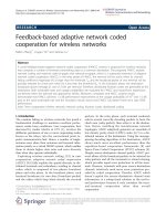
Figure 3.8: Outage probability of relay networks with different scenarios
Fig. 3.8 indicates that the performance of the system model based on network coding with
multiple-relay is better than others. This can be explained as follows:
• Using MRC at the destination to combine the signals from R1 and R2 into a better channel
makes the transmission between the relays and destination become more reliability. Thus,
this system model will be more stable than an other which only uses one relay.
• In multiple-relay networks, there is no interaction between source i and relay j (i, j =
1, 2 and i <> j) and between the relay R1 and the relay R2 . It means that x1 is only
transmitted by the source S1 on s1 d and R1 on r1 d link. While, in multiple-relay networks
using network coding, x1 is carried on 3 link s1 d, r1 d and r2 d.
18
Conclusions and Future Works
In this thesis, we consider the effects of network coding on cooperative relay networks. Instead
of using traditional DF relaying, propose to use selection DF relaying which is designed to overcome
the weaknesses of DF relaying. By using the instantaneous channel gains, we calculate exactly the
outage probabilities of systems models, i.e relaying networks with and without network coding,
under a Rayleigh fading environment. Comparing between the system models that only use one
relay, we see that the robustness of the networks will be reduced when network coding is applied.
However, when we increase the number of the relays (using 2 relays), the performance of network
may be increase strongly, even it is better than the case in which network coding is not used.
Therefore, it may be said that in some cases, network coding also improves the robustness of the
network. Our proposed system model may be sub-optimal, but it has achieved what we expected.
19
Bibliography
[1] [Online]. Available: scheme
[2] K. J. RAYLIU, A. K. SADEK, W. SU, and A. KWASINSKI, Cooperative Communications and Networking, ninth dover printing, tenth gpo printing ed.
New York: Dover,
1964.
[3] G. Liu and Y. Meng, “Completely opportunistic approach to network coding using in
wireless network,” in Proc. 4th Int. Conf. Wireless Communications, Networking and
Mobile Computing (WiCOM 2008), 2008, pp. 1–3.
[4] D. Tse and P. Viswanath, Fundamentals ofWireless Communication.
CambridgeUni-
versity Press, 2005.
[5] Y. R. W and Z. Z, “Distributed source coding for satel-lite communications,” IEEE
Transactions on Information Theory, vol. 45, p. 11111120, 1999.
[6] R. Ahlswede, N. Cai, S.-Y. R. Li, and R. W. Yeung, “Network information flow,” IEEE
transactions on information theory, vol. 46, pp. 1204–1216, 2000.
[7] M. Xiao and M. Skoglund, “Design of network codes for multiple-user multiple-relay
wireless networks,” in ISIT 2009, June, 2009.
[8] L. Li, K. Fan, and D. Long, “Nonlinear network coding: A case study,” in IMECS 2008,
March 2008.
[9] R. W. Yeung, Information Theory and Network Coding. Springer, May 31, 2008.
[10] T. Noguchi, T. Matsuda, and MikiYamamoto, “Performance evaluation of new multicast
architecture with network coding,” IEICE Trans. Comm, vol. E86-B, pp. 1788–1795,
2003.
20