tính toán tải trọng gió và động đất
Bạn đang xem bản rút gọn của tài liệu. Xem và tải ngay bản đầy đủ của tài liệu tại đây (24.22 MB, 919 trang )
DK2447_title 10/18/04 8:57 AM Page 1
WIND and EARTHQUAKE
RESISTANT BUILDINGS
STRUCTURAL ANALYSIS AND DESIGN
BUNGALE S. TARANATH Ph.D., S.E.
John A. Martin & Associates, Inc.
Los Angeles, California
MARCEL
MARCEL DEKKER
DEKKER
NEW YORK
CEE7.qxd
10/20/04
2:05 PM
Page 1
Civil and Environmental Engineering
A Series of Reference Books and Textbooks
Editor
Michael D. Meyer
Department of Civil and Environmental Engineering
Georgia Institute of Technology
Atlanta, Georgia
1.
2.
3.
4.
Preliminary Design of Bridges for Architects and Engineers, Michele Melaragno
Concrete Formwork Systems, Awad S. Hanna
Multilayered Aquifer Systems: Fundamentals and Applications, Alexander H.-D. Cheng
Matrix Analysis of Structural Dynamics: Applications and Earthquake Engineering,
Franklin Y. Cheng
5. Hazardous Gases Underground: Applications to Tunnel Engineering, Barry R. Doyle
6. Cold-Formed Steel Structures to the AISI Specification, Gregory J. Hancock,
Thomas M. Murray, Duane S. Ellifritt
7. Fundamentals of Infrastructure Engineering: Civil Engineering Systems:
Second Edition, Revised and Expanded, Patrick H. McDonald
8. Handbook of Pollution Control and Waste Minimization, Abbas Ghassemi
9. Introduction to Approximate Solution Techniques, Numerical Modeling,
and Finite Element Methods, Victor N. Kaliakin
10. Geotechnical Engineering: Principles and Practices of Soil Mechanics
and Foundation Engineering, V. N. S. Murthy
11. Estimating Building Costs, Calin M. Popescu, Kan Phaobunjong, Nuntapong Ovararin
12. Chemical Grouting and Soil Stabilization: Third Edition, Revised and Expanded,
Reuben H. Karol
13. Multifunctional Cement-Based Materials, Deborah D. L. Chung
14. Reinforced Soil Engineering: Advances in Research and Practice, Hoe I. Ling,
Dov Leshchinsky, and Fumio Tatsuoka
15. Project Scheduling Handbook, Jonathan F. Hutchings
16. Environmental Pollution Control Microbiology, Ross E. McKinney
17. Hydraulics of Spillways and Energy Dissipators, R. M. Khatsuria
18. Wind and Earthquake Resistant Buildings: Structural Analysis and Design,
Bungale S. Taranath
Additional Volumes in Production
DK2447_half 10/13/04 4:58 PM Page 1
WIND and EARTHQUAKE
RESISTANT BUILDINGS
STRUCTURAL ANALYSIS AND DESIGN
Cover design courtesy of Margaret Martin.
Although great care has been taken to provide accurate and current information, neither the author(s) nor the
publisher, nor anyone else associated with this publication, shall be liable for any loss, damage, or liability directly
or indirectly caused or alleged to be caused by this book. The material contained herein is not intended to provide
specific advice or recommendations for any specific situation.
Trademark notice: Product or corporate names may be trademarks or registered trademarks and are used only for
identification and explanation without intent to infringe.
Library of Congress Cataloging-in-Publication Data
A catalog record for this book is available from the Library of Congress.
ISBN: 0-8247-5934-6
This book is printed on acid-free paper.
Headquarters
Marcel Dekker, 270 Madison Avenue, New York, NY 10016, U.S.A.
tel: 212-696-9000; fax: 212-685-4540
Distribution and Customer Service
Marcel Dekker, Cimarron Road, Monticello, New York 12701, U.S.A.
tel: 800-228-1160; fax: 845-796-1772
World Wide Web
The publisher offers discounts on this book when ordered in bulk quantities. For more information, write to
Special Sales/Professional Marketing at the headquarters address above.
Copyright © 2005 by Marcel Dekker. All Rights Reserved.
Neither this book nor any part may be reproduced or transmitted in any form or by any means, electronic or
mechanical, including photocopying, microfilming, and recording, or by any information storage and retrieval
system, without permission in writing from the publisher.
Current printing (last digit):
10 9 8 7 6 5 4 3 2 1
PRINTED IN THE UNITED STATES OF AMERICA
This book is dedicated to my wife
SAROJA
without whose patience and devotion, this book would not be.
Acknowledgments
I wish to express my sincere appreciation and thanks to the entire staff of John A. Martin
and Associates (JAMA), Los Angeles, CA for their help in this endeavor. Special thanks
are extended to John A. Martin, Sr. (Jack) and John A. Martin, Jr. (Trailer) for their support
and encouragement during the preparation of this book.
Numerous JAMA engineers reviewed various portions of the manuscript and provided
valuable comments. In particular, I am indebted to
Dr. Roger Di Julio, Chapters 2 and 6
Ryan Wilkerson, Chapters 1 and 2
Kai Chen Tu, Chapter 1
Kan B. Patel, Chapter 5
Louis Choi and Vernon Gong, Chapter 3
Brett W. Beekman, Ron Lee, and Filbert Apanay, Chapter 4
Farro Tofighi, Chapters 3 and 5
Chuck G. Whitaker, Chapter 8
Additionally, the text had the privilege of review from the following individuals. My sincere
thanks to
Dr. Hussain Bhatia, Senior Structural Engineer, OSHPD, Sacramento, CA, Chapters 2
and 6
M. V. Ravindra, President, LeMessurier Consultants, Cambridge, MA, and Rao V.
Nunna, Structural Engineer, S. B. Barnes Associates, Chapter 7
Kenneth B. Wiesner, Principal (retired), LeMessurier Consultants, Cambridge, MA,
Chapter 8
Appreciation is acknowledged to the following JAMA individuals who were helpful to the
author at one or more times during preparation of the manuscript:
Margaret Martin for preparing artwork for the book cover
Marvin F. Mittelstaedt, Tony Galina, Richard Lubas, Murjani Oseguera, April Oseguera,
and Nicholas Jesus Oseguera for their help in preparation of the artwork
Andrew Besirof, Evita Santiago- Oseguera, Ron Lee, Hung C. Lee, Chaoying Luo, and
Walter Steimle, all of JAMA; Greg L. Clapp of Martin and Peltyon; and Gary Chock
of Martin and Chock; and Charles D. Keyes of Martin and Martin, for providing
photographs
Ron M. Tong, Robert Barker, Ahmad H. Azad, Dr. Farzad Naeim, Kal Benuska, Mike
Baltay, Mark Day, Dan Pattapongse, and Eric D. Brown for their general help
Ivy Policar, Rima Roerish, Betty D. Cooper, and Rosie Nyenke for typing parts of the
manuscript
Raul Oseguera, Andrew Gannon, Ferdinand Encarnacion, and Ignacio Morales for duplicating the manuscript
v
vi
Acknowledgments
Sincere thanks are extended to
B. J. Clark and Brian Black, formerly of Marcel Dekker, for their guidance in preparation
of the manuscript
Edwin Shlemon, Associate Principal, ARUP, Los Angeles, CA, for reviewing the book
proposal and making valuable suggestions
Mark Johnson, International Code Council, for his help and encouragement
Jan Fisher, Project Manager, Publication Services, Inc., and editor Jennifer Putman for
their cooperation, help, and patience in transforming the manuscript into this book
Srinivas Bhat, and S. Venkatesh of Kruthi Computer Services, Bangalore, India, for their
artwork suggestions.
Special thanks to my family:
My daughter, Dr. Anupama Taranath; son-in-law, Dr. Rajesh Rao; and son, Abhiman
Taranath, provided a great deal of help and support. My sincere thanks to them.
Most deserving of special gratitude is my wife, Saroja. My source of inspiration, she
helped in all aspects of this venture—from manuscript’s inception to final proofreading.
Her companionship made the arduous task of writing this book a less formidable activity.
My profound admiration and appreciation are extended to her for unconditional love,
encouragement, support, and devotion. Without her patience and absolute commitment,
this modest contribution to structural engineering could not have been made.
Preface
The primary objective of this book is to disseminate information on the latest concepts,
techniques, and design data to structural engineers engaged in the design of wind- and
seismic-resistant buildings. Integral to the book are recent advances in seismic design,
particularly those related to buildings in zones of low and moderate seismicity. These
stipulations, reflected in the latest provisions of American Society of Civil Engineers
(ASCE) 7-02, International Building Code (IBC)-03, and National Fire Protection Association (NFPA) 5000, are likely to be adopted as a design standard by local code agencies.
There now exists the unprecedented possibility of a single standard becoming a basis for
earthquake-resistant design virtually in the entire United States, as well as in other nations
that base their codes on U.S. practices. By incorporating these and the latest provisions
of American Concrete Institute (ACI) 318-02, American Institute of Steel Construction
(AISC) 341-02, and Federal Emergency Management Agency (FEMA) 356 and 350 series,
this book equips designers with up-to-date information to execute safe designs, in accordance with the latest regulations.
Chapter 1 presents methods of determining design wind loads using the provisions
of ASCE 7-02, National Building Code of Canada (NBCC) 1995, and 1997 Uniform
Building Code (UBC). Wind-tunnel procedures are discussed, including analytical methods
for determining along-wind and across-wind response.
Chapter 2 discusses the seismic design of buildings, emphasizing their behavior
under large inelastic cyclic deformations. Design provisions of ASCE 7-02 (IBC-03, NFPA
5000) and UBC-97 that call for detailing requirements to assure seismic performance
beyond the elastic range are discussed using static, dynamic, and time-history procedures.
The foregone design approach—in which the magnitude of seismic force and level of
detailing were strictly a function of the structure’s location—is compared with the most
recent provisions, in which these are not only a function of the structure’s location, but
also of its use and occupancy, and the type of soil it rests upon. This comparison will be
particularly useful for engineers practicing in many seismically low- and moderate-risk
areas of the United States, who previously did not have to deal with seismic design and
detailing, but are now obligated to do so. Also explored are the seismic design of structural
elements, nonstructural components, and equipment. The chapter concludes with a review
of structural dynamic theory.
The design of steel buildings for lateral loads is the subject of Chapter 3. Traditional
as well as modern bracing systems are discussed, including outrigger and belt truss systems
that have become the workhorse of lateral bracing systems for super-tall buildings. The
lateral design of concentric and eccentric braced frames, moment frames with reduced
beam section, and welded flange plate connections are discussed, using provisions of
ASCE 341-02 and FEMA-350 as source documents.
Chapter 4 addresses concrete structural systems such as flat slab frames, coupled
shear walls, frame tubes, and exterior diagonal and bundled tubes. Basic concepts of
vii
viii
Preface
structural behavior that emphasize the importance of joint design are discussed. Using
design provisions of ACI 318-02, the chapter also details building systems such as ordinary,
intermediate, and special reinforced concrete moment frames, and structural walls.
The design of buildings using a blend of structural steel and reinforced concrete,
often referred to as composite construction, is the subject of Chapter 5. The design of
composite beams, columns, and shear walls is discussed, along with building systems such
as composite shear walls and megaframes.
Chapter 6 is devoted to the structural rehabilitation of seismically vulnerable buildings. Design differences between a code-sponsored approach and the concept of ductility
trade-off for strength are discussed, including seismic deficiencies and common upgrade
methods.
Chapter 7 is dedicated to the gravity design of vertical and horizontal elements of
steel, concrete, and composite buildings. In addition to common framing types, novel
systems such as haunch and stub girder systems are also discussed. Considerable coverage
is given to the design of prestressed concrete members based on the concept of load
balancing.
The final chapter is devoted to a wide range of topics. Chapter 8 begins with a
discussion of the evolution of different structural forms particularly applicable to the design
of tall buildings. Case studies of buildings with structural systems that range from runof-the-mill bracing techniques to unique composite systems—including megaframes and
external superbraced frames—are examined. Next, reduction of building occupants’
motion perceptions using damping devices is considered, including tuned mass dampers,
slashing water dampers, tuned liquid column dampers, and simple and nested pendulum
dampers. Panel zone effects, differential shortening of columns, floor-leveling problems,
and floor vibrations are studied, followed by a description of seismic base isolation and
energy dissipation techniques. The chapter concludes with an explanation of bucklingrestrained bracing systems that permit plastic yielding of compression braces.
The book speaks to a multifold audience. It is directed toward consulting engineers
and engineers employed by federal, state, and local governments. Within the academy, the
book will be helpful to educators and students alike, particularly as a teaching tool in
courses for students who have completed an introductory course in structural engineering
and seek a deeper understanding of structural design principles and practice. To assist
readers in visualizing the response of structural systems, numerous illustrations and practical design problems are provided throughout the text.
Wind- and Earthquake-Resistant Buildings integrates the design aspects of steel,
concrete, and composite buildings within a single text. It is my hope that it will serve as
a comprehensive design reference for practicing engineers and educators.
October 2004
Bungale S. Taranath Ph.D., S.E.
John A. Martin & Associates
Structural Engineers
1212 S. Flower Street
Los Ageles, California 90015
www.johnmartin.com
Contents
Chapter 1. Wind Loads .................................................................................................. 1
1.1. Design Considerations .... 1
1.2. Nature of Wind .... 2
1.2.1.
Types of wind .... 2
1.3. Characteristics of Wind .... 3
1.3.1.
1.3.2.
1.3.3.
1.3.4.
1.3.5.
1.3.6.
Variation of Wind Velocity with Height .... 3
Wind Turbulence .... 4
Probabilistic Approach .... 5
Vortex Shedding .... 7
Dynamic Nature of Wind .... 10
Cladding Pressures .... 10
1.4. Code Provisions for Wind Loads .... 13
1.4.1.
1.4.2.
1.4.3.
Uniform Building Code, 1997:
Wind Load Provisions .... 15
ASCE 7-02: Wind Load Provisions .... 24
National Building Code of Canada (NBCC 1995):
Wind Load Provisions .... 68
1.5. Wind-Tunnel Engineering .... 83
1.5.1.
1.5.2.
1.5.3.
1.5.4.
1.5.5.
Rigid Model .... 84
Aeroelastic Study .... 86
High-Frequency Base Force Balance Model .... 91
Pedestrian Wind Studies .... 93
Motion Perception: Human Response to Building Motions .... 97
Chapter 2. Seismic Design ............................................................................................ 99
2.1. Building Behavior .... 101
2.1.1.
2.1.2.
2.1.3.
2.1.4.
Influence of Soil .... 102
Damping .... 103
Building Motions and Deflections .... 104
Building Drift .... 104
2.2. Seismic Design Concept .... 104
2.2.1.
2.2.2.
2.2.3.
2.2.4.
2.2.5.
2.2.6.
2.2.7.
2.2.8.
2.2.9.
2.2.10.
2.2.11.
2.2.12.
2.2.13.
2.2.14.
Structural Response .... 105
Load Path .... 105
Demands of Earthquake Motions .... 106
Response of Elements Attached to Buildings .... 106
Adjacent Buildings .... 106
Irregular Buildings .... 107
Lateral-Force-Resisting Systems .... 108
Diaphragms .... 111
Ductility .... 111
Damage Control Features .... 112
Continuous Load Path .... 113
Redundancy .... 114
Configuration .... 114
Dynamic Analysis .... 114
ix
x
Contents
2.3. Uniform Building Code, 1997 Edition: Seismic Provisions .... 132
2.3.1.
2.3.2.
2.3.3.
2.3.4.
2.3.5.
2.3.6.
2.3.7.
2.3.8.
2.3.9.
2.3.10.
2.3.11.
2.3.12.
2.3.13.
2.3.14.
2.3.15.
2.3.16.
2.3.17.
2.3.18.
2.3.19.
2.3.20.
Building Irregularities .... 133
Design Base Shear, V .... 136
Seismic Zone Factor Z .... 139
Seismic Importance Factor IE .... 141
Building Period T .... 141
Structural System Coefficient R .... 142
Seismic Dead Load W .... 142
Seismic Coefficients Cv and Ca .... 144
Soil Profile Types .... 146
Seismic Source Type A, B, and C .... 147
Near Source Factors Na and Nv .... 147
Distribution of Lateral Force Fx .... 147
Story Shear Vx and Overturning Moment Mx .... 149
Torsion .... 149
Reliability/Redundancy Factor r .... 149
Drift Limitations .... 150
Deformation Compatibility .... 151
Load Combinations .... 155
Design Example, 1997 UBC: Static Procedure .... 158
OSHPD and DSA Seismic Design Requirements .... 165
2.4. ASCE 7-02, IBC 2003, and NFPA 5000: Seismic Provisions .... 169
2.4.1.
2.4.2.
2.4.3.
2.4.4.
2.4.5.
2.4.6
2.4.7.
2.4.8.
Seismic Design Highlights: ASCE 7-02, IBC-03, NFPA 5000 .... 171
ASCE 7-02: Detail Description of Seismic Provisions .... 175
IBC 2003, NFPA 5000 (ASCE 7-02) Equivalent Lateral-Force
Procedure .... 190
Dynamic Analysis Procedure .... 202
Design and Detailing Requirements .... 203
Seismic Design Example: Static Procedure, IBC 2003
(ASCE 7-02, NFPA 5000) .... 205
Seismic Design Example: Dynamic Analysis Procedure (Response Spectrum
Analysis), Hand Calculations .... 212
Anatomy of Computer Response Spectrum Analyses
(In Other Words, What Goes on in the Black Box) .... 220
2.5. Seismic Design of Structural Elements, Nonstructural Components,
and Equipment; 1997 UBC Provisions .... 231
2.5.1.
2.5.2.
2.5.3.
2.5.4.
Architectural Components .... 232
Exterior Ornaments and Appendages .... 233
Component Behavior .... 233
1997 UBC Provisions .... 235
2.6. Dynamic Analysis Theory .... 244
2.6.1.
2.6.2.
2.6.3.
Single-Degree-of-Freedom Systems .... 245
Multidegree-of-Freedom Systems .... 248
Modal Superposition Method .... 250
2.7. Chapter Summary .... 258
Chapter 3. Steel Buildings ....................................................................................... 261
3.1. Rigid Frames (Moment Frames) .... 262
3.1.1.
3.1.2.
3.1.3.
Deflection Characteristics .... 264
Cantilever Bending Component .... 265
Shear Racking Component .... 265
3.2. Braced Frames .... 266
3.2.1.
Types of Braces .... 269
Contents
xi
3.3. Staggered Truss System .... 270
3.3.1.
3.3.2.
3.3.3.
Floor System .... 271
Columns .... 274
Trusses .... 275
3.4. Eccentric Braced Frame (EBF) .... 275
3.4.1.
3.4.2.
3.4.3.
3.4.4.
3.4.5.
3.4.6.
Ductility .... 276
Behavior .... 276
Essential Features of Link .... 276
Analysis and Design Considerations .... 277
Deflection Considerations .... 278
Conclusions .... 278
3.5. Interacting System of Braced and Rigid Frames .... 278
3.5.1.
Behavior .... 281
3.6. Outrigger and Belt Truss Systems .... 282
3.6.1.
3.6.2.
3.6.3.
3.6.4.
3.6.5.
Behavior .... 284
Deflection Calculations .... 285
Optimum Location of a Single Outrigger .... 290
Optimum Location of Two Outriggers .... 295
Recommendations for Optimum Locations
of Belt and Outrigger Trusses .... 297
3.7. Framed Tube System .... 298
3.7.1.
3.7.2.
3.8.
3.9.
3.10.
3.11.
Behavior .... 298
Shear Lag Phenomenon .... 300
Irregular Tube .... 302
Trussed Tube .... 303
Bundled Tube .... 305
Seismic Design .... 307
3.11.1. Concentric Braced Frames .... 308
3.11.2. Eccentric Braced Frame (EBF) .... 324
3.11.3. Moment Frames .... 335
Chapter 4. Concrete Buildings ................................................................................ 349
4.1. Structural Systems .... 349
4.1.1.
4.1.2.
4.1.3.
4.1.4.
4.1.5.
4.1.6.
4.1.7.
4.1.8.
4.1.9.
4.1.10.
4.1.11.
4.1.12.
Flat Slab–Beam System .... 349
Flat Slab–Frame with Shear Walls .... 352
Coupled Shear Walls .... 352
Rigid Frame .... 352
Tube System with Widely Spaced Columns .... 353
Rigid Frame with Haunch Girders .... 353
Core-Supported Structures .... 354
Shear Wall–Frame Interaction .... 354
Frame Tube System .... 356
Exterior Diagonal Tube .... 357
Bundled Tube .... 358
Miscellaneous Systems .... 358
4.2. Seismic Design .... 361
4.2.1.
4.2.2.
4.2.3.
4.2.4.
4.2.5.
4.2.6.
4.2.7.
Load Factors, Strength Reduction Factors, and Load Combinations .... 369
Integrity Reinforcement .... 371
Intermediate Moment-Resisting Frames .... 373
Special Moment-Resisting Frames .... 377
Shear Walls .... 387
Frame Members Not Designed to Resist Earthquake Forces .... 390
Diaphragms .... 391
xii
Contents
4.2.8.
4.2.9.
Foundations .... 392
Design Examples .... 394
Chapter 5. Composite Buildings ............................................................................. 443
5.1. Composite Elements .... 444
5.1.1.
5.1.2.
5.1.3.
5.1.4.
5.1.5.
Composite Slabs .... 444
Composite Frame Beams .... 445
Composite Columns .... 445
Composite Diagonals .... 449
Composite Shear Walls .... 449
5.2. Composite Building Systems .... 450
5.2.1.
5.2.2.
5.2.3.
5.2.4.
5.2.5.
Composite Shear Wall Systems .... 452
Shear Wall–Frame Interacting Systems .... 454
Tube Systems .... 455
Vertically Mixed Systems .... 458
Mega Frames with Super Columns .... 459
5.3. Example Projects .... 460
5.3.1.
5.3.2.
5.3.3.
5.3.4.
Buildings with Composite Steel Pipe Columns .... 460
Buildings with Formed Composite Columns .... 462
Buildings with Composite Shear Walls and Frames .... 465
Building with Composite Tube System .... 468
5.4. Super-Tall Buildings: Structural Concept .... 468
5.5. Seismic Composite Systems .... 470
5.5.1.
5.5.2.
5.5.3.
5.5.4.
Moment-Resisting Frames .... 474
Braced Frames .... 480
Composite Shear Walls .... 485
Example Projects .... 489
Chapter 6. Seismic Rehabilitation of Existing Buildings ...................................... 499
6.1. Code-Sponsored Design .... 500
6.2. Alternate Design Philosophy .... 501
6.3. Code Provisions for Seismic Upgrade .... 502
6.4. Building Deformations .... 504
6.5. Common Deficiencies and Upgrade Methods .... 505
6.5.1.
6.5.2.
6.5.3.
6.5.4.
6.5.5.
6.5.6.
6.5.7.
6.5.8.
6.5.9.
6.5.10.
6.5.11.
Diaphragms .... 506
Concrete Shear Walls .... 513
Reinforcing of Steel-Braced Frames .... 520
Infilling of Moment Frames .... 521
Reinforced Concrete Moment Frames .... 521
Steel Moment Frames .... 522
Open Storefront .... 523
Clerestory .... 523
Shallow Foundations .... 523
Rehabilitation Measures for Deep Foundations .... 525
Nonstructural Elements .... 525
6.6. FEMA 356: Prestandard and Commentary
on the Seismic Rehabilitation of Buildings .... 527
6.6.1.
6.6.2.
6.6.3.
6.6.4.
Overview of Performance Levels .... 527
Permitted Design Methods .... 529
Systematic Rehabilitation .... 530
FEMA 356: Design Examples .... 554
6.7. Summary of FEMA 356 .... 559
Contents
xiii
6.8. Fiber-Reinforced Polymer Systems
for Strengthening of Concrete Buildings .... 560
6.8.1.
6.8.2.
6.8.3.
Mechanical Properties and Behavior .... 560
Design Philosophy .... 561
Flexural Design .... 561
6.9. Seismic Strengthening Details .... 562
6.9.1.
Common Strategies for Seismic Strengthening .... 564
Chapter 7. Gravity Systems ....................................................................................... 585
7.1. Structural Steel .... 585
7.1.1.
7.1.2.
7.1.3.
7.2.
Concrete Systems .... 603
7.2.1.
7.2.2.
7.2.3.
7.2.4.
7.3.
One-Way Slabs .... 604
T-Beam Design .... 611
Two-Way Slabs .... 620
Unit Structural Quantities .... 626
Prestressed Concrete Systems .... 627
7.3.1.
7.3.2.
7.3.3.
7.3.4.
7.3.5.
7.3.6.
7.3.7.
7.4.
Tension Members .... 586
Members Subject to Bending .... 589
Members Subject to Compression .... 593
Prestressing Methods .... 629
Materials .... 630
Design Considerations .... 632
Cracking Problems in Post-Tensioned Floors .... 634
Concept of Secondary Moments .... 636
Step-by-Step Design Procedure .... 648
Strength Design for Flexure .... 675
Composite Gravity Systems .... 683
7.4.1.
7.4.2.
7.4.3.
7.4.4.
7.4.5.
7.4.6.
Composite Metal Deck .... 683
Composite Beams .... 699
Composite Haunch Girders .... 716
Composite Trusses .... 718
Composite Stub Girders .... 718
Composite Columns .... 727
Chapter 8. Special Topics ........................................................................................... 731
8.1. Tall Buildings .... 731
8.1.1.
8.1.2.
8.1.3.
8.1.4.
8.2.
Damping Devices for Reducing Motion Perception .... 796
8.2.1.
8.2.2.
8.2.3.
8.2.4.
8.2.5.
8.2.6.
8.3.
8.4.
Passive Viscoelastic Dampers .... 798
Tuned Mass Damper .... 798
Sloshing Water Damper .... 803
Tuned Liquid Column Damper .... 803
Simple Pendulum Damper .... 805
Nested Pendulum Damper .... 807
Panel Zone Effects .... 807
Differential Shortening of Columns .... 812
8.4.1.
8.4.2.
8.5.
Structural Concepts .... 732
Case Studies .... 734
Future of Tall Buildings .... 789
Unit Structural Quantities .... 791
Simplified Method .... 816
Column Shortening Verification During Construction .... 826
Floor-Leveling Problems .... 828
xiv
8.6.
Contents
Floor Vibrations .... 829
8.6.1.
8.6.2.
8.7.
General Discussion .... 829
Response Calculations .... 831
Seismic Isolation .... 835
8.7.1.
8.7.2.
8.7.3.
8.8.
8.9.
Salient Features .... 837
Mechanical Properties of Seismic Isolation Systems .... 839
Seismically Isolated Structures: ASCE 7-02 Design Provisions .... 842
Passive Energy Dissipation Systems .... 864
Buckling-Restrained Braced Frame .... 867
Selected References .... 873
Appendix A
Index .... 879
Conversion Factors: U.S. Customary to SI Units .... 877
1
Wind Loads
1.1.
DESIGN CONSIDERATIONS
Windstorms pose a variety of problems in buildings—particularly in tall buildings—causing
concerns for building owners, insurers, and engineers alike. Hurricane winds are the largest
single cause of economic and insured losses due to natural disasters, well ahead of
earthquakes and floods. For example, in the United States between 1986 and 1993,
hurricanes and tornadoes caused about $41 billion in insured catastrophic losses, compared
with $6.18 billion for all other natural hazards combined, hurricanes being the largest
contributor to the losses. In Europe in 1900 alone, four winter storms caused $10 billion
in insured losses, and an estimated $15 billion in economic losses. According to one 1999
insurance industry estimate, the natural catastrophe resulting in the largest amount of
insured losses up to that date was hurricane Andrew in 1992 ($16.5 billion). The runnerup, the 1994 Northridge earthquake, resulted in $12.5 billion in reported losses.
In designing for wind, a building cannot be considered independent of its surroundings. The influence of nearby buildings and land configuration on the sway response of
the building can be substantial. The sway at the top of a tall building caused by wind may
not be seen by a passerby, but may be of concern to those occupying its top floors. There
is scant evidence that winds, except those due to a tornado or hurricane, have caused major
structural damage to new buildings. However, a modern skyscraper, with lightweight
curtain walls, dry partitions, and high-strength materials, is more prone to wind motion
problems than the early skyscrapers, which had the weight advantage of masonry partitions,
heavy stone facades, and massive structural members.
To be sure, all buildings sway during windstorms, but the motion in earlier tall
buildings with heavy full-height partitions has usually been imperceptible and certainly
has not been a cause for concern. Structural innovations and lightweight construction
technology have reduced the stiffness, mass, and damping characteristics of modern
buildings. In buildings experiencing wind motion problems, objects may vibrate, doors
and chandeliers may swing, pictures may lean, and books may fall off shelves. If the
building has a twisting action, its occupants may get an illusory sense that the world
outside is moving, creating symptoms of vertigo and disorientation. In more violent
storms, windows may break, creating safety problems for pedestrians below. Sometimes,
strange and frightening noises are heard by the occupants as the wind shakes elevators,
strains floors and walls, and whistles around the sides.
Following are some of the criteria that are important in designing for wind:
1. Strength and stability.
2. Fatigue in structural members and connections caused by fluctuating wind
loads.
3. Excessive lateral deflection that may cause cracking of internal partitions and
external cladding, misalignment of mechanical systems, and possible permanent deformations of nonstructural elements.
1
2
Wind and Earthquake Resistant Buildings
4. Frequency and amplitude of sway that can cause discomfort to occupants of
tall, flexible buildings.
5. Possible buffeting that may increase the magnitude of wind velocities on
neighboring buildings.
6. Wind-induced discomfort in pedestrian areas caused by intense surface winds.
7. Annoying acoustical disturbances.
8. Resonance of building oscillations with vibrations of elevator hoist ropes.
1.2.
NATURE OF WIND
Wind is the term used for air in motion and is usually applied to the natural horizontal
motion of the atmosphere. Motion in a vertical or nearly vertical direction is called a current.
Movement of air near the surface of the earth is three-dimensional, with horizontal motion
much greater than the vertical motion. Vertical air motion is of importance in meteorology
but is of less importance near the ground surface. On the other hand, the horizontal motion
of air, particularly the gradual retardation of wind speed and the high turbulence that occurs
near the ground surface, are of importance in building engineering. In urban areas, this
zone of turbulence extends to a height of approximately one-quarter of a mile aboveground,
and is called the surface boundary layer. Above this layer, the horizontal airflow is no longer
influenced by the ground effect. The wind speed at this height is called the gradient wind
speed, and it is precisely in this boundary layer where most human activity is conducted.
Therefore, how wind effects are felt within this zone is of great concern.
Although one cannot see the wind, it is a common observation that its flow is quite
complex and turbulent in nature. Imagine taking a walk outside on a reasonably windy day.
You no doubt experience the constant flow of wind, but intermittently you will experience
sudden gusts of rushing air. This sudden variation in wind speed, called gustiness or
turbulence, plays an important part in determining building oscillations.
1.2.1.
Types of wind
Winds that are of interest in the design of buildings can be classified into three major
types: prevailing winds, seasonal winds, and local winds.
1. Prevailing winds. Surface air moving toward the low-pressure equatorial belt is
called prevailing winds or trade winds. In the northern hemisphere, the northerly
wind blowing toward the equator is deflected by the rotation of the earth to
become northeasterly and is known as the northeast trade wind. The corresponding wind in the southern hemisphere is called the southeast trade wind.
2. Seasonal winds. The air over the land is warmer in summer and colder in
winter than the air adjacent to oceans during the same seasons. During summer,
the continents become seats of low pressure, with wind blowing in from the
colder oceans. In winter, the continents experience high pressure with winds
directed toward the warmer oceans. These movements of air caused by variations in pressure difference are called seasonal winds. The monsoons of the
China Sea and the Indian Ocean are an examples.
3. Local winds. Local winds are those associated with the regional phenomena
and include whirlwinds and thunderstorms. These are caused by daily changes
in temperature and pressure, generating local effects in winds. The daily
variations in temperature and pressure may occur over irregular terrain, causing
valley and mountain breezes.
Wind Loads
3
All three types of wind are of equal importance in design. However, for the purpose
of evaluating wind loads, the characteristics of the prevailing and seasonal winds are
analytically studied together, whereas those of local winds are studied separately. This
grouping is to distinguish between the widely differing scale of fluctuations of the winds;
prevailing and seasonal wind speeds fluctuate over a period of several months, whereas
the local winds vary almost every minute, The variations in the speed of prevailing and
seasonal winds are referred to as fluctuations in mean velocity. The variations in the local
winds, are referred to as gusts.
The flow of wind, unlike that of other fluids, is not steady and fluctuates in a random
fashion. Because of this, wind loads imposed on buildings are studied statistically.
1.3.
CHARACTERISTICS OF WIND
The flow of wind is complex because many flow situations arise from the interaction of
wind with structures. However, in wind engineering, simplifications are made to arrive at
design wind loads by distinguishing the following characteristics:
•
•
•
•
•
1.3.1.
Variation of wind velocity with height.
Wind turbulence.
Statistical probability.
Vortex shedding phenomenon.
Dynamic nature of wind–structure interaction.
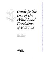
Variation of Wind Velocity with Height
The viscosity of air reduces its velocity adjacent to the earth’s surface to almost zero, as
shown in Fig. 1.1. A retarding effect occurs in the wind layers near the ground, and these
inner layers in turn successively slow the outer layers. The slowing down is reduced at
each layer as the height increases, and eventually becomes negligibly small. The height
at which velocity ceases to increase is called the gradient height, and the corresponding
velocity, the gradient velocity. This characteristic of variation of wind velocity with height
is a well-understood phenomenon, as evidenced by higher design pressures specified at
higher elevations in most building codes.
At heights of approximately 1200 ft (366 m) aboveground, the wind speed is virtually
unaffected by surface friction, and its movement is solely dependent on prevailing seasonal
and local wind effects. The height through which the wind speed is affected by topography
is called the atmospheric boundary layer. The wind speed profile within this layer is
given by
Vz = Vg(Z/Zg)1/α
(1.1)
where
Vz = mean wind speed at height Z aboveground
Vg = gradient wind speed assumed constant above the boundary layer
Z = height aboveground
Zg = nominal height of boundary layer, which depends on the exposure (Values for
Zg are given in Fig. 1.1.)
α = power law coefficient
4
Wind and Earthquake Resistant Buildings
Figure 1.1.
Influence of exposure terrain on variation of wind velocity with height.
With known values of mean wind speed at gradient height and exponent α, wind
speeds at height Z are calculated by using Eq. (1.1). The exponent 1/α and the depth of
boundary layer Zg vary with terrain roughness and the averaging time used in calculating
wind speed. α ranges from a low of 0.087 for open country of 0.20 for built-up urban
areas, signifying that wind speed reaches its maximum value over a greater height in an
urban terrain than in the open country.
1.3.2.
Wind Turbulence
Motion of wind is turbulent. A concise mathematical definition of turbulence is difficult
to give, except to state that it occurs in wind flow because air has a very low viscosity—about
one-sixteenth that of water. Any movement of air at speeds greater than 2 to 3 mph (0.9 to
1.3 m/s) is turbulent, causing particles of air to move randomly in all directions. This is
in contrast to the laminar flow of particles of heavy fluids, which move predominantly
parallel to the direction of flow.
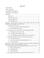
For structural engineering purposes, velocity of wind can be considered as having
two components: a mean velocity component that increases with height, and a turbulent
velocity that remains the same over height (Fig. 1.1a). Similarly, the wind pressures, which
are proportional to the square of the velocities, also fluctuate as shown in Fig. 1.2. The
total pressure Pt at any instant t is given by the relation
Pt = P + P′
(1.2)
Wind Loads
Figure 1.1a.
5
Variation of wind velocity with time; at any instant t, velocity Vt = V ′ + V.
where
Pt = pressure at instant t
P = average or mean pressure
P ′ = instantaneous pressure fluctuation
1.3.3.
Probabilistic Approach
In many engineering sciences the intensity of certain events is considered to be a function
of the duration recurrence interval (return period). For example, in hydrology the intensity
of rainfall expected in a region is considered in terms of a return period because the rainfall
expected once in 10 years is less than the one expected once every 50 years. Similarly,
in wind engineering the speed of wind is considered to vary with return periods. For
example, the fastest-mile wind 33 ft (10 m) above ground in Dallas, TX, corresponding
Figure 1.2.
Pt = P′ + P.
Schematic representation of mean and gust pressure. At any instant t, the pressure
6
Wind and Earthquake Resistant Buildings
to a 50-year return period, is 67 mph (30 m/s), compared to the value of 71 mph (31.7 m/
s) for a 100-year recurrence interval.
A 50-year return-period wind of 67 mph (30 m/s) means that on the average, Dallas
will experience a wind faster than 67 mph within a period of 50 years. A return period of
50 years corresponds to a probability of occurrence of 1/50 = 0.02 = 2%. Thus the chance
that a wind exceeding 67 mph (30 m/s) will occur in Dallas within a given year is 2%.
Suppose a building is designed for a 100-year lifetime using a design wind speed of
67 mph. What is the probability that this wind will exceed the design speed within the
lifetime of the structure? The probability that this wind speed will not be exceeded in any
year is 49/50. The probability that this speed will not be exceeded 100 years in a row is
(49/50)100. Therefore, the probability that this wind speed will be exceeded at least once
in 100 years is
49
1−
50
100
= 0.87 = 87%
This signifies that although a wind with low annual probability of occurrence (such
as a 50-year wind) is used to design structures, there still exists a high probability of the
wind being exceeded within the lifetime of the structure. However, in structural engineering
practice it is believed that the actual probability of overstressing a structure is much less
because of the factors of safety and the generally conservative values used in design.
It is important to understand the notion of probability of occurrence of design wind
speeds during the service life of buildings. The general expression for probability P that
a design wind speed will be exceeded at least once during the exposed period of n years
is given by
P = 1 – (1 – Pa)n
(1.3)
where
Pa = annual probability of being exceeded (reciprocal of the mean recurrence interval)
n = exposure period in years
Consider a building in Dallas designed for a 50-year service life instead of 100 years.
The probability of exceeding the design wind speed at least once during the 50-year
lifetime of the building is
P = 1 – (1 – 0.02)50 = 1 – 0.36 = 0.64 = 64%
The probability that wind speeds of a given magnitude will be exceeded increases
with a longer exposure period of the building and the mean recurrence interval used in
the design. Values of P for a given mean recurrence interval and a given exposure period
are shown in Table 1.1.
Wind velocities (measured with anemometers usually installed at airports across the
country) are necessarily averages of the fluctuating velocities measured during a finite
interval of time. The value usually reported in the United States, until the publication of
the American Society of Civil Engineers’ ASCE 7-95 standard, was the average of the
velocities recorded during the time it takes a horizontal column of air 1 mile long to pass
a fixed point. For example, if a 1-mile column of air is moving at an average velocity of
60 mph, it passes an anemometer in 60 seconds, the reported velocity being the average of
the velocities recorded these 60 seconds. The fastest mile is the highest velocity in one day.
The annual extreme mile is the largest of the daily maximums. Furthermore, since the
annual extreme mile varies from year to year, wind pressures used in design are based on
Wind Loads
7
TABLE 1.1 Probability of Exceeding Design Wind Speed During Design Life
of Building
Annual
probability
Pa
Mean
recurrence
interval
(1/Pa ) years
1
5
10
25
50
100
0.1
0.04
0.034
0.02
0.013
0.01
0.0067
0.005
10
25
30
50
75
100
150
200
0.1
0.04
0.034
0.02
0.013
0.01
0.0067
0.005
0.41
0.18
0.15
0.10
0.06
0.05
0.03
0.02
0.15
0.34
0.29
0.18
0.12
0.10
0.06
0.05
0.93
0.64
0.58
0.40
0.28
0.22
0.15
0.10
0.994
0.87
0.82
0.64
0.49
0.40
0.28
0.22
0.999
0.98
0.97
0.87
0.73
0.64
0.49
0.39
Exposure period (design life), n (years)
a wind velocity having a specific mean recurrence interval. Mean recurrence intervals of
20 and 50 years are generally used in building design, the former interval for determining
the comfort of occupants in tall buildings subject to wind storms, and the latter for designing
lateral resisting elements.
1.3.4.
Vortex Shedding
In general, wind buffeting against a bluff body gets diverted in three mutually perpendicular directions, giving rise to forces and moments about the three directions. Although
all six components, as shown in Fig.1.3, are significant in aeronautical engineering, in
civil and structural work, the force and moment corresponding to the vertical axis (lift and
yawing moment) are of little significance. Therefore, aside from the uplift forces on large
roof areas, the flow of wind is simplified and considered two-dimensional, as shown in
Fig.1.4, consisting of along wind and transverse wind.
Along wind—or simply wind—is the term used to refer to drag forces, and transverse
wind is the term used to describe crosswind. The crosswind response causing motion in a
plane perpendicular to the direction of wind typically dominates over the along-wind
response for tall buildings. Consider a prismatic building subjected to a smooth wind flow.
Figure 1.3.
Six components of wind.
8
Figure 1.4.
Wind and Earthquake Resistant Buildings
Simplified two-dimensional flow of wind.
The originally parallel upwind streamlines are displaced on either side of the building,
Fig.1.5. This results in spiral vortices being shed periodically from the sides into the
downstream flow of wind, called the wake. At relatively low wind speeds of, say, 50 to 60
mph (22.3 to 26.8 m/s), the vortices are shed symmetrically in pairs, one from each side.
When the vortices are shed, i.e., break away from the surface of the building, an impulse
is applied in the transverse direction.
At low wind speeds, since the shedding occurs at the same instant on either side of
the building, there is no tendency for the building to vibrate in the transverse direction. It
is therefore subject to along-wind oscillations parallel to the wind direction. At higher
speeds, the vortices are shed alternately, first from one and then from the other side. When
this occurs, there is an impulse in the along-wind direction as before, but in addition, there
is an impulse in the transverse direction. The transverse impulses are, however, applied
alternately to the left and then to the right. The frequency of transverse impulse is precisely
half that of the along-wind impulse. This type of shedding, which gives rise to structural
vibrations in the flow direction as well as in the transverse direction, is called vortex
shedding or the Karman vortex street, a phenomenon well known in the field of fluid
mechanics.
Figure 1.5.
Vortex-shedding phenomenon.