BS EN 199242018 Eurocode 2 Design of concrete structures Part 4: Design of fastenings for use in concrete
Bạn đang xem bản rút gọn của tài liệu. Xem và tải ngay bản đầy đủ của tài liệu tại đây (5.18 MB, 129 trang )
Licensed to: Alexandru Dondera, Cowi, 2019-01-04 13:06
DS/EN 1992-4:2018
Dansk standard
2018-07-23
Eurocode 2 – Betonkonstruktione
Betonkonstruk tionerr –
Del 4: Dimensionering af befæstelsesdele
til anvendelse i beton
Eurocode 2 – Design of concrete structures –
Part 4: Design of fastenings for use in concrete
DANSK STANDARD
Danish Standards Association
Göteborg Plads 1
DK-2150 Nordhavn
Tel: +45 39 96 61 01
Tel: +45 39 96 61 01
www.ds.dk
© Dansk Standard - Eftertryk uden till adelse forbudt
Licensed to: Alexandru Dondera, Cowi, 2019-01-04 13:06
© Danish Standards Foundation
DS/EN 1992-4:2018
København
DS projekt: M274444
ICS: 91.010.30; 91.080.40
Første del af denne publikations betegnelse er:
DS/EN, hvilket betyder, at det er en europæisk standard, der har status som dansk standard.
Denne publikations overensstemmelse er:
IDT med: EN 1992-4:201
1992-4:2018
8
DS-publikationen er på engelsk.
Denne publikation erstatter: DS/CEN/TS 1992-4-1:2009,
1992-4-1:2009, DS/CEN
DS/CEN/TS
/TS 1992
1992-4-2:2009
-4-2:2009,, DS/
DS/CEN/TS
CEN/TS 1992-4-3:2009
1992-4-3:2009,, DS/CEN/
TS 1992-4-4:2009,
1992-4-4:2009, DS/CEN
DS/CEN/TS
/TS 1992-4-5:2009
DS-publikationstyper
Dansk Standard udgiver forskellige publikationsty per.
Typen på denne publikation fremgår af fors iden.
Der kan være tale om:
Dansk standard
• standard, der er udarbejdet på nationalt niveau, eller
eller som er
er baseret på et andet lands nationale standard, eller
• standard, der er udarbejdet
udarbejdet på internationalt
internationalt og/eller europæisk
europæisk niveau,
niveau, og som har fået status
status som dansk standard
DS-information
• publikation, der er udarbejdet på nationalt niveau, og som ikke har opnået statu s som standard , eller
• publikation, der er udarbejdet på internationalt og/eller
og/eller europæisk niveau, og som ikke har fået status som
standard, fx en teknisk rapport, eller
• europæisk præstandard
DS-håndbog
• samling af standarder, eventuelt
eventuelt suppleret med informativ t materiale
DS-hæfte
• publikation med informativ t materiale
Til disse publikationstyper kan endvidere udgives
• tillæg og rettelsesblade
DS-publikationsform
Publikationstyperne udgives i forskellig form som henholdsvis
• fuldtekstpublikat ion
(publikationen er tryk t i sin helhed)
• godkendelsesblad
(publipukationen leveres i kopi med et tryk t DS-omslag)
• elektronisk
(publikationen leveres på et elektronisk medie)
DS-betegnelse
Alle DS-publikationers betegnelse begy nder med DS efterfulgt af et eller lere præikser og et nr., fx DS 383, DS/EN 5414 osv. Hvis
der efter nr. er angivet et A eller Cor, betyder det, enten at det er et tillæg eller et rettelsesblad til hovedstanda rden, eller at det er
indført i hovedstandarden.
DS-betegnelse angives på forsiden.
Overensstemmelse med anden publikation:
Overensstemmelse kan enten være IDT, EQV, NEQ eller MOD
Når publikationen er identisk med en given publikation.
• IDT:
Når publikationen teknisk er i overensstemmelse med en given publikation, men
• EQV:
præsentationen er ændret.
Når publikationen teknisk eller præsentationsmæssigt ikke er i overensstemmelse med en
• NEQ:
given standard, men udarbejdet på baggrund af denne.
Når publikationen er modiiceret i forhold til en given publikation.
• MOD:
Licensed to: Alexandru Dondera, Cowi, 2019-01-04 13:06
© Danish Standards Foundation
DS/EN 1992-4:2018
EN 1992-4
EUROPEAN STANDARD
NORME EUROPÉENNE
EUROPÄISCHE NORM
July 2018
ICS 91.010.30; 91.080.40
Supersedes CEN/TS 1992-4-1:2009,
CEN/TS 1992-4-2:2009, CEN/TS 1992-4-3:2009,
CEN/TS 1992-4-4:2009, CEN/TS 1992-4-5:2009
English Version
Eurocode 2 - Design of concrete structures - Part 4: Design
of fastenings for use in concrete
Eurocode 2 - Calcul des structures en béton - Partie 4 :
Conception et calcul des éléments de fixation pour
béton
Eurocode 2 - Bemessung und Konstruktion von
Stahlbeton- und Spannbetontragwerken - Teil 4:
Bemessung der Verankerung von Befestigungen in
Beton
This European Standard was approved by CEN on 9 March 2018.
CEN members are bound to comply with the CEN/CENELEC Internal Regulations which stipulate the conditions for giving this
European Standard the status of a national standard without any alteration. Up-to-date lists and bibliographical references
concerning such national standards may be obtained on application to the CEN-CENELEC
CEN-CENELEC Management Centre or to any CEN
member.
This European Standard exists in three official versions (English, French, German). A version in any other language made by
translation under the responsibility of a CEN member into its own language and notified to the CEN-CENELEC
CEN-CENELEC Management
Centre has the same status as the official versions.
CEN members are the national
n ational standards bodies of Austria, Belgium, Bulgaria, Croatia, Cyprus, Czech Republic, Denmark, Estonia,
Finland, Former Yugoslav Republic of Macedonia, France, Germany, Greece, Hungary, Iceland, Ireland, Italy, Latvia, Lithuania,
Luxembourg, Malta, Netherlands, Norway, Poland, Portugal, Romania, Serbia, Slovakia, Slovenia, Spain, Sweden, Switzerland,
Turkey and United Kingdom.
EUROPEAN COMMITTEE FOR STANDARDIZATION
STANDARDIZATION
COMITÉ EUROPÉEN DE NORMALISATION
EUROPÄISCHES KOMITEE FÜR NORMUNG
CEN-CENELEC Management Centre: Rue de la Science 23, B-1040 Brussels
© 2018 CEN
All rights
rights of exploitation in any form and by any means reserved
reserved
worldwide for CEN national Members.
Ref. No. EN 1992-4:2018 E
Licensed to: Alexandru Dondera, Cowi, 2019-01-04 13:06
© Danish Standards Foundation
DS/EN 1992-4:2018
EN 1992-4:2018 (E)
Contents
Page
European foreword .......................................................................... ............................................................................. 5
1
1.1
1.2
1.3
1.4
1.5
1.6
Scope ............................................................................. ...................................................................................... . 7
General ...................................................................................... .......................................................................... 7
Type of fasteners and fastening groups ............................................................................. ..................... 7
Fastener dimensions and materials ..................................................................................... .................... 9
Fastener loading ........................................................................................................................................... 10
Concrete strength and type ...................................................................................................................... 10
Concrete member loading ................................................................................ ......................................... 10
2
Normative references ................................................................................................................................. 10
3
Terms, definitions, symbols and abbreviations ................................................................................ 11
3.1
Terms and definitions ................................................................................................................................ 11
3.2
Symbols and abbreviations ...................................................................................................................... 18
3.2.1 Indices .............................................................................................................................................................. 18
3.2.2 Superscripts ................................................................................................................................................... 19
3.2.3 Actions and resistances (listing in alphabetical order) ................................................................. 20
3.2.4 Concrete and steel ................................................................................ ........................................................ 25
3.2.5 Fasteners and fastenings, reinforcement ................................................................................ ............ 26
3.2.6 Units .................................................................................................................................................................. 28
4
4.1
4.2
4.3
4.4
4.4.1
4.4.2
4.5
4.6
4.7
Basis of design ............................................................................................................................................... 28
General ............................................................................................................................................................. 28
Required verifications ................................................................................. ............................................... 29
Design format ................................................................................................................................................ 29
Verification by the partial factor method ............................................................................ ................ 30
Partial factors for actions ...................................................................................... .................................... 30
Partial factors for resistance............................................................................. ....................................... 30
Project specification .................................................................................. .................................................. 33
Installation of fasteners ......................................................................... .................................................... 34
Determination of concrete condition ................................................................................................... 34
5
Durability ........................................................................................................................................................ 35
6
Derivation of forces acting on fasteners – analysis .......................................................................... 35
6.1
General ............................................................................................................................................................. 35
6.2
Headed fasteners and post-installed fasteners ................................................................................. 36
6.2.1 Tension loads .................................................................................. ............................................................... 36
6.2.2 Shear loads ..................................................................................................................................................... 39
6.3
Anchor channels ........................................................................... ................................................................ 42
6.3.1 General ............................................................................................................................................................. 42
6.3.2 Tension loads .................................................................................. ............................................................... 43
6.3.3 Shear loads ..................................................................................................................................................... 44
6.4
Forces assigned to supplementary reinforcement .......................................................................... 45
6.4.1 General .................................................................................. ........................................................................... 45
6.4.2 Tension loads ................................................................................ ................................................................. 45
6.4.3 Shear loads ..................................................................................................................................................... 45
7
7.1
2
Verification of ultimate limit state .................................................................................... ..................... 46
General ............................................................................................................................................................. 46
Licensed to: Alexandru Dondera, Cowi, 2019-01-04 13:06
© Danish Standards Foundation
DS/EN 1992-4:2018
EN 1992-4:2018 (E)
7.2
Headed and post-installed fasteners ..................................................................................................... 47
7.2.1 Tension load ................................................................................................................. .................................. 47
7.2.2 Shear load ............................................................................ ............................................................................ 62
7.2.3 Combined tension and shear loads ................................................................................................... ..... 74
7.3
Fasteners in redundant non-structural systems ............................................................................... 76
7.4
Anchor channels....................................................................................... ..................................................... 76
7.4.1 Tension load ............................................................................................................... .................................... 76
7.4.2 Shear load .......................................................................... .............................................................................. 85
7.4.3 Combined tension and shear loads ................................................................................................ ........ 93
8
8.1
8.2
8.3
8.3.1
8.3.2
8.3.3
Verification of ultimate limit state for fatigue loading .................. ................................................. 95
General ............................................................................................................................................................. 95
Derivation of forces acting on fasteners – analysis .......................................................................... 95
Resistance ................................................................................... ..................................................................... 96
Tension load ......................................................................................................... .......................................... 96
Shear load ........................................................................................................................................................ 97
Combined tension and shear load ............................................................................................. ............. 97
9
9.1
9.2
9.3
9.4
Verification for seismic loading............................................................................................................... 98
General ............................................................................................................................................................. 98
Requirements .................................................................................... ............................................................. 98
Derivation of forces acting on fasteners .......................................................................... .................. 100
Resistance ............................................................................ ......................................................................... 100
10
Verification for fire resistance .................................................................................. ............................ 100
11
Verification of serviceability limit state ....................................................................................... ..... 100
Annex A (normative) Additional rules for verification of concrete elements due to loads
applied by fastenings................................................................................................................................ 101
A.1
General .......................................................................................................................................................... 101
A.2
Verification of the shear resistance of the concrete member ................................................. .. 101
Annex B (informative) Durability ................................................................................. ...................................... 103
B.1
General .......................................................................................................................................................... 103
B.2
Fasteners in dry, internal conditions ................................................................................................. 103
B.3
Fasteners in external atmospheric or in permanently damp internal exposure
condition .................................................................................. ..................................................................... 103
B.4
Fasteners in high corrosion exposure by chloride and sulphur dioxide ............................... 103
Annex C (normative) Design of fastenings under seismic actions .......................................................... 104
C.1
General .......................................................................................................................................................... 104
C.2
Performance categories .......................................................................................................................... 104
C.3
Design criteria ............................................................................................................................................ 105
C.4
Derivation of forces acting on fasteners – analysis ....................................................................... 107
C.4.1 General .......................................................................................................................................................... 107
C.4.2 Addition to EN 1998-1:2004, 4.3.3.5 .................................................................................... ............... 108
C.4.3 Addition to EN 1998-1:2004, 4.3.5.1 ..................................................................................... .............. 108
C.4.4 Additions and alterations to EN 1998-1:2004, 4.3.5.2 ................................................................. 108
C.4.5 Additions and alterations to EN 1998-1:2004, 4.3.5.4 ................................................................. 110
C.5
Resistance ............................................................................. ........................................................................ 110
C.6
Displacements of fasteners .................................................................................................................... 113
Annex D (informative) Exposure to fire – design method .......................................................................... 114
D.1
General .......................................................................................................................................................... 114
D.2
Partial factors ................................................................................ .............................................................. 114
D.3
Actions .................................................................................. ......................................................................... 114
3
Licensed to: Alexandru Dondera, Cowi, 2019-01-04 13:06
© Danish Standards Foundation
DS/EN 1992-4:2018
EN 1992-4:2018 (E)
D.4
D.4.1
D.4.2
D.4.3
D.4.4
Resistance ........................................................................................................................... .......................... 115
General .......................................................................... ................................................................................. 115
Tension load......................................................................... ........................................................................ 115
Shear load ............................................................................. ........................................................................ 117
Combined tension and shear load ............................................................................ ............................ 118
Annex E (normative) Characteristics for the design of fastenings to be provided by European
Technical Products Specification ................................................. ........................................................ 119
Annex F (normative) Assumptions for design provisions regarding execution of fastenings ...... 122
F.1
General ...................................................................................... ..................................................................... 122
F.2
Post-installed fasteners ........................................................................ ................................................... 122
F.3
Headed fasteners .......................................................................... .............................................................. 123
F.4
Anchor channels ........................................................................... .............................................................. 123
Annex G (informative) Design of post-installed fasteners – simplifi ed methods............................... 124
G.1
General ................................................................................... ........................................................................ 124
G.2
Method B........................................................................................................................................................ 124
G.3
Method C ........................................................................................................................... ............................. 125
Bibliography .......................................................................... ..................................................................................... 126
4
Licensed to: Alexandru Dondera, Cowi, 2019-01-04 13:06
© Danish Standards Foundation
DS/EN 1992-4:2018
EN 1992-4:2018 (E)
European foreword
This document (EN 1992-4:2018) has been prepared by Technical Committee CEN/TC 250 “Structural
Eurocodes”, the secretariat of which is held by BSI.
This European Standard shall be given the status of a national standard, either by publication of an
identical text or by endorsement, at the latest by January 2019 and conflicting national standards shall
be withdrawn at the latest by January 2019.
Attention is drawn to the possibility that some of the elements of this document may be the subject of
patent rights. CEN [and/or CENELEC] shall not be held responsible for identifying any or all such patent
rights.
This document supersedes CEN/TS 1992-4-1:2009, CEN/TS 1992-4-2:2009, CEN/TS 1992-4-3:2009,
CEN/TS 1992-4-4:2009 and CEN/TS 1992-4-5:2009.
This document has been prepared under a mandate given to CEN by the European Commission and the
European Free Trade Association.
EN 1992 is composed of the following parts:
— EN 1992-1-1, Eurocode 2: Design of concrete structures — Part 1-1: General rules and rules for
buildings;
— EN 1992-1-2, Eurocode 2: Design of concrete structures — Part 1-2: General rules — Structural fire
design;
— EN 1992-2, Eurocode 2 — Design of concrete structures — Concrete bridges — Design and detailing
rules;
— EN 1992-3, Eurocode 2 — Design of concrete structures — Part 3: Liquid retaining and containment
structures;
— EN 1992-4, Eurocode 2 — Design of concrete structures — Part 4: Design of fastenings for use in
concrete.
The numerical values for partial factors and other reliability parameters are recommended values. The
recommended values apply when:
a)
the fasteners comply with the requirements of 1.2 (3), and
b) the installation complies with the requirements of 4.6.
5
Licensed to: Alexandru Dondera, Cowi, 2019-01-04 13:06
© Danish Standards Foundation
DS/EN 1992-4:2018
EN 1992-4:2018 (E)
National Annex for EN 1992-4
This EN gives values with Notes indicating where national choices may have to be made. When this EN is
made available at national level it may be followed by a National Annex containing all Nationally
Determined Parameters to be used for the design of fastenings according to this EN for use in the relevant
country.
National choice of the partial factors and reliability parameters is allowed in design according to this EN
in the following sections:
4.4.1(2);
4.4.2.2(2);
4.4.2.3;
4.4.2.4;
4.7(2);
C.2(2);
C.4.4(1);
C.4.4(3);
D.2(2).
According to the CEN-CENELEC Internal Regulations, the national standards organizations of the
following countries are bound to implement this European Standard: Austria, Belgium, Bulgaria, Croatia,
Cyprus, Czech Republic, Denmark, Estonia, Finland, Former Yugoslav Republic of Macedonia, France,
Germany, Greece, Hungary, Iceland, Ireland, Italy, Latvia, Lithuania, Luxembourg, Malta, Netherlands,
Norway, Poland, Portugal, Romania, Serbia, Slovakia, Slovenia, Spain, Sweden, Switzerland, Turkey and
the United Kingdom.
6
Licensed to: Alexandru Dondera, Cowi, 2019-01-04 13:06
© Danish Standards Foundation
DS/EN 1992-4:2018
EN 1992-4:2018 (E)
1
Scope
1.1 General
(1) This European Standard provides a design method for fastenings (connection of structural elements
and non-structural elements to structural components), which are used to transmit actions to the
concrete. This design method uses physical models which are based on a combination of tests and
numerical analysis consistent with EN 1990:2002, 5.2.
Additional rules for the transmission of the fastener loads within the concrete member to its supports
are given in EN 1992-1-1 and Annex A of this EN.
Inserts embedded in precast concrete elements during production, under Factory Production Control
(FPC) conditions and with the due reinforcement, intended for use only during transient situations for
lifting and handling, are covered by CEN/TR 15728.
(2) This EN is intended for safety related applications in which the failure of fastenings may result in
collapse or partial collapse of the structure, cause risk to human life or lead to significant economic loss.
In this context it also covers non-structural elements.
(3) The support of the fixture can be either statically determinate or statically indeterminate. Each
support can consist of one fastener or a group of fasteners.
(4) This EN is valid for applications which fall within the scope of the EN 1992 series. In applications
where special considerations apply, e.g. nuclear power plants or civil defence structures, modifications
can be necessary.
(5) This EN does not cover the design of the fixture. Rules for the design of the fixture are given in the
appropriate Standards meeting the requirements on the fixture as given in this EN.
(6) This document relies on characteristic resistances and distances which are stated in a European
Technical Product Specification (see Annex E). At least the characteristics of Annex E are given in a
European Technical Product Specification for the corresponding loading conditions providing a basis for
the design methods of this EN.
1.2 Type of fasteners and fastening groups
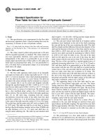
(1) This EN uses the fastener design theory 1) (see Figure 1.1) and applies to:
a)
cast-in fasteners such as headed fasteners, anchor channels with rigid connection (e.g. welded,
forged) between anchor and channel;
b) post-installed mechanical fasteners such as expansion fasteners, undercut fasteners and concrete
screws;
c)
post-installed bonded fasteners and bonded expansion fasteners.
(2) For other types of fasteners, modifications of the design provisions can be necessary.
(3) This EN applies to fasteners with established suitability for the specified application in concrete
covered by provisions, which refer to this EN and provide data required by this EN. The suitability of the
fastener is stated in the relevant European Technical Product Specification.
1)
In fastener design theory the concrete tensile capacity is directly used to transfer loads into the concrete component.
7
Licensed to: Alexandru Dondera, Cowi, 2019-01-04 13:06
© Danish Standards Foundation
DS/EN 1992-4:2018
EN 1992-4:2018 (E)
Figure 1.1 — Fastener design theory — Example
(4) This EN applies to single fasteners and groups of fasteners. In a group of fasteners, the loads are
applied to the individual fasteners of the group by means of a common fixture. In a group of fasteners,
this European Standard applies only if fasteners of t he same type and size are used.
(5) The configurations of fastenings with cast-in place headed fasteners and post-installed fasteners
covered by this EN are shown in Figure 1.2.
(6) For anchor channels, the number of anchors is not limited.
8
Licensed to: Alexandru Dondera, Cowi, 2019-01-04 13:06
© Danish Standards Foundation
DS/EN 1992-4:2018
EN 1992-4:2018 (E)
Key
1
fastener
2
steel plate
a)
Fastenings without hole clearance for all edge distances and for all load directions, and fastenings with hole
clearance according to Table 6.1 situated far from edges
(c
i
{
≥ max 10hef ; 60d nom
}) for
all load
directions and fastenings with hole clearance according to Table 6.1 situated near to an edge
( c i < max {10hef ; 60d nom } ) loaded in tension only
b)
(
{
Fastenings with hole clearance according to Table 6.1 situated near to an edge c i < max 10 hef ; 60d nom
})
for all load directions
Figure 1.2 — Configuration of fastenings with headed and post-installed fasteners covered by
this EN
(7) Post-installed ribbed reinforcing bars used to connect concrete members are covered by a European
Technical Product Specification.
1.3 Fastener dimensions and materials
(1) This EN applies to fasteners with a minimum diameter or a minimum thread size of 6 mm (M6) or a
corresponding cross section. In case of fasteners for fastening statically indeterminate non-structural
systems as addressed in 7.3, the minimum thread size is 5 mm (M5). The maximum diameter of the
fastener is not limited for tension loading but is limited to 60 mm for shear loading.
(2) EN 1992-4 applies to fasteners with embedment depth hef ≥ 40 mm. Only for fastening statically
indeterminate non-structural systems as addressed in 7.3 fasteners with effective embedment depth of
at least 30 mm are considered, which may be reduced to 25 mm in internal exposure conditions. For
fastenings with post-installed bonded anchors, only fasteners with an embedment depth hef ≤ 20d are
covered. The actual value for a particular fastener may be found in the relevant European Technical
Product Specification.
9
Licensed to: Alexandru Dondera, Cowi, 2019-01-04 13:06
© Danish Standards Foundation
DS/EN 1992-4:2018
EN 1992-4:2018 (E)
(3) This EN covers metal fasteners made of either carbon steel (EN ISO 898-1 and EN ISO 898-2,
EN 10025-1, EN 10080), stainless steel (EN 10088-2 and EN 10088-3, EN ISO 3506-1 and
EN ISO 3506-2) or malleable cast iron ( ISO 5922). The surface of the steel can be coated or uncoated. This
EN is valid for fasteners with a nominal steel tensile strength f uk ≤ 1 000 N / mm 2 . This limit does not
apply to concrete screws.
1.4 Fastener loading
(1) Loading on the fastenings covered by this document can be static, quasi-static, fatigue and seismic.
The suitability of the fastener to resist fatigue and seismic loadings is specifically stated in the relevant
European Technical Product Specification. Anchor channels subjected to fatigue loading or seismic
loading are not covered by this EN.
(2) The loading on the fastener resulting from the actions on the fixture (e.g. tension, shear, bending or
torsion moments or any combination thereof) will generally be axial tension and/or shear. When the
shear force is applied with a lever arm a bending moment on the fastener will arise. EN 1992-4 only
considers axial compression on the fixture which is transmitted to the concrete either directly to the
concrete surface without acting on the embedded fastener load transfer mechanism or via fasteners
suitable for resisting compression.
(3) In case of anchor channels, shear in the direction of the longitudinal axis of the channel is not covered
by this EN.
NOTE
Design rules for anchor channels with loads acting in the direction of the longitudinal axis of the anchor
channel can be found in CEN/TR 17080, Design of fastenings for use in concrete — Anchor channels — S upplementary
rules.
(4) Design of fastenings under fire exposure is covered by this EN (see informative Annex D).
1.5 Concrete strength and type
This EN is valid for fasteners installed in members made of compacted normal weight concrete without
fibres with strength classes in the range C12/15 to C90/105 all in accordance with EN 206. The range of
concrete strength classes in which particular fasteners may be used is given in the relevant European
Technical Product Specification and may be more restrictive than s tated above.
1.6 Concrete member loading
In general, fasteners are prequalified for applications in concrete members under static loading. If the
concrete member is subjected to fatigue or seismic loading, prequalification of the fast ener specific to this
type of loading and a corresponding European Technical Product Specification are required.
2
Normative references
The following documents are referred to in the text in such a way that some or all of their content
constitutes requirements of this document. For dated references, only the edition cited applies. For
undated references, the latest edition of th e referenced document (including any amendments) applies.
EN 206, Concrete - Specification, performance, production and conformity
EN 1990:2002, Eurocode - Basis of structural design
EN 1991 (all parts), Eurocode 1: Actions on structures
EN 1992-1-1:2004, Eurocode 2: Design of concrete structures - Part 1-1: General rules and rules for
buildings
10
Licensed to: Alexandru Dondera, Cowi, 2019-01-04 13:06
© Danish Standards Foundation
DS/EN 1992-4:2018
EN 1992-4:2018 (E)
EN 1992-1-2, Eurocode 2: Design of concrete structures - Part 1-2: General rules - Structural fire design
EN 1998 (all parts), Eurocode 8: Design of structures for earthquake resistance
3
Terms, definitions, symbols and abbreviations
3.1 Terms and definitions
For the purposes of this document, the following terms and definitions apply.
ISO and IEC maintain terminological databases for use in standardization at the following addresses:
•
IEC Electropedia: available at />
•
ISO Online browsing platform: a vailable at />
3.1.1
anchor
fastener
element made of steel or malleable iron either cast into concrete or post-installed into a hardened
concrete member and used to transmit applied loads (see Figures 3.1 to 3.3)
Note 1 to entry:
The term anchor is used in the context of anchor channels.
3.1.2
anchor channel
steel profile with rigidly connected anchors (see Figure 3.2) installed prior to concreting
Note 1 to entry: In the case of anchor channels, two or more steel anchors are rigidly connected to the back of the
channel and embedded in concrete.
3.1.3
attached element
structural or non-structural component that is connected to the attachment
3.1.4
attachment
fixture
assembly that transmits loads to the fastener or anchor channel
3.1.5
base material
concrete member in which the fastener or anchor channel is installed
3.1.6
bending
bending effect induced by a shear load applied with a lever arm with respect to the surface of the concrete
member
11
Licensed to: Alexandru Dondera, Cowi, 2019-01-04 13:06
© Danish Standards Foundation
DS/EN 1992-4:2018
EN 1992-4:2018 (E)
3.1.7
bonded expansion fastener
bonded fastener designed such that the fastener element can move relative to the hardened bonding
compound resulting in follow-up expansion (see Figure 3.3 h))
3.1.8
bonded fastener
fastener placed into a hole in hardened concrete, which derives its resistance from a bonding compound
placed between the wall of the hole in the concrete and the embedded portion of the fastener
(see Figure 3.3 g))
3.1.9
cast-in fastener
headed bolt, headed stud, internal threaded socket with head at the embedded end or anchor channel
installed before placing the concrete, see also headed fastener
3.1.10
channel bolt
screw or bolt which connects the element to be fixed to the anchor channel (see Figure 3.2)
3.1.11
characteristic edge distance
edge distance required to ensure that the edge does not influence the characteristic resistance of a
fastening
3.1.12
characteristic resistance
5 % fractile of the resistance (value with a 95 % probability of being exceeded, with a confidence level of
90 %)
3.1.13
characteristic spacing
spacing required to ensure the characteristic resistance of a single fastener
3.1.14
combined pull-out and concrete failure of bonded fasteners
failure mode in which failure occurs at the interface between the bonding material and the base material
or between the bonding material and the fastener element (bond failure) and contains a concrete cone at
the top end
3.1.15
combined tension and shear loads
oblique load
tension and shear load applied simultaneously
3.1.16
concrete blow-out failure
spalling of the concrete on the side face of the concrete element at the level of the embedded head with
no major breakout at the top concrete surface
Note 1 to entry:
12
This is usually associated with fasteners with small side cover and deep embedment.
Licensed to: Alexandru Dondera, Cowi, 2019-01-04 13:06
© Danish Standards Foundation
DS/EN 1992-4:2018
EN 1992-4:2018 (E)
3.1.17
concrete breakout failure
failure that corresponds to a wedge or cone of concrete surrounding the fastener, group of fasteners or
anchor of an anchor channel being separated from the base material
3.1.18
concrete pry-out failure
failure that corresponds to the formation of a concrete spall opposite to the loading direction under shear
loading
3.1.19
concrete related failure modes
3.1.19.1
failure modes under tension loading
pull-out failure, combined pull-out and concrete failure (bonded fasteners), concrete cone failure,
concrete blow-out failure, concrete splitting failure, anchorage failure of supplementary reinforcement
3.1.19.2
failure modes under shear loading
concrete pry-out failure, concrete edge failure
3.1.20
concrete screw
threaded fastener screwed into a predrilled hole where threads create a mechanical interlock with the
concrete (see Figure 3.3 f))
3.1.21
concrete splitting failure
concrete failure mode in which the concrete fractures along a plane passing through the axis of the
fastener or fasteners or anchors of an anchor channel
3.1.22
deformation-controlled expansion fastener
post-installed fastener that derives its tensile resistance by expansion against the side of the drilled hole
through movement of an internal plug in the sleeve (see Figure 3.3 c)) or through movement of the sleeve
over an expansion element (plug), and with which, once set, no further expansion can occur
3.1.23
displacement
movement of the loaded end of the fastener relative to the concrete member into which it is installed in
the direction of the applied load; or, in the case of anchor channels, movement of a channel bolt
(see Figure 3.2) or the anchor channel relative to the concrete element
Note 1 to entry: In tension tests, displacement is measured parallel to the axis of the fastener; in shear tests,
displacement is measured perpendicular to the axis of the fastener.
3.1.24
ductile steel element
element with sufficient ductility
Note 1 to entry:
The ductility conditions are given in the relevant subclauses.
13
Licensed to: Alexandru Dondera, Cowi, 2019-01-04 13:06
© Danish Standards Foundation
DS/EN 1992-4:2018
EN 1992-4:2018 (E)
3.1.25
edge distance
distance from the edge of the concrete member to the centre of the fastener or anchor of an anchor
channel
3.1.26
effective embedment depth
overall depth through which the fastener or anchor of an anchor channel transfers force to the
surrounding concrete; see Figures 3.1 to 3.3
3.1.27
European Technical Product Specification
European Standard (EN), European Technical Assessment (ETA) for fastener or anchor channel based on
a European Assessment Document (EAD) or a transparent and reproducible assessment that complies
with all requirements of the relevant EAD
3.1.28
fastening
assembly of fixture and fasteners or anchor channel used to transmit loads to concrete
Key
a)
without anchor plate
b)
with a large anchor plate at least in one direction, b1 > 0,5 hnom or t > 0, 2 hnom
c)
with a small anchor plate in both directions, b1 ≤ 0,5 hnom and t ≤ 0, 2 hnom
Figure 3.1 — Definition of effective embedment depth hef for headed fasteners
14
Licensed to: Alexandru Dondera, Cowi, 2019-01-04 13:06
© Danish Standards Foundation
DS/EN 1992-4:2018
EN 1992-4:2018 (E)
Key
1
anchor
2
connection between anchor and channel
3
channel
4
channel lip
5
channel bolt
a)
hef for anchor channels (see 7.4.1.5 (1) and 7.4.1.5 (1) b))
b)
*
hef
for anchor channels (see 7.4.1.5 (1) a))
Figure 3.2 — Definitions for anchor channels
15
Licensed to: Alexandru Dondera, Cowi, 2019-01-04 13:06
© Danish Standards Foundation
DS/EN 1992-4:2018
EN 1992-4:2018 (E)
Key
a)
torque-controlled fastener, sleeve type
e)
undercut fastener, type 2
b)
torque-controlled fastener, wedge type
f)
concrete screw
c)
deformation-controlled fastener
g)
bonded fastener
d)
undercut fastener, type 1
h)
bonded expansion fastener
Figure 3.3 — Definition of effective embedment depth hef for post-installed fasteners – Examples
3.1.29
flexure
bending effect in the channel of an anchor channel induced by a tension load
3.1.30
group of fasteners
number of fasteners with identical dimensions and characteristics acting together to support a common
attachment, where the spacing of the fasteners does not exceed the characteristic spacing
3.1.31
headed fastener
cast-in steel fastener with a head at the embedded end (see Figure 3.1) that derives its tensile resistance
from mechanical interlock at the head of the fastener
3.1.32
mechanical interlock
load transfer to a concrete member via i nterlocking surfaces
3.1.33
minimum edge distance
smallest allowable distance to allow adequate placing and compaction of concrete (cast-in place
fasteners) and to avoid damage to the concrete during installation (post-installed fasteners), given in the
European Technical Product Specification
3.1.34
minimum member thickness
smallest value for member thickness, in which a fastener or an anchor channel is allowed to be installed,
given in the European Technical Product Specification
16
Licensed to: Alexandru Dondera, Cowi, 2019-01-04 13:06
© Danish Standards Foundation
DS/EN 1992-4:2018
EN 1992-4:2018 (E)
3.1.35
minimum spacing
smallest value for distance between two fasteners to allow adequate placing and compaction of concrete
(cast-in fasteners) and to avoid damage to the concrete during installation (post-installed fasteners),
measured centreline to centreline, given in the E uropean Technical Product Specification
3.1.36
post-installed fastener
fastener installed in hardened concrete (see Figure 3.3)
3.1.37
pull-out failure
both pull-out failure of mechanical fasteners and combined pull-out and concrete failure of bonded
fasteners
3.1.38
pull-out failure of mechanical fasteners
failure mode in which the fastener pulls out of the concrete without development of the full concrete
resistance or in case of post-installed mechanical fasteners a failure mode in which the fastener body
pulls through the expansion sleeve without development of the f ull concrete resistance
3.1.39
shear load
load acting parallel to the concrete surface and transversely with respect to the longitudinal axis of the
channel; load applied perpendicular to the longitudinal axis of a fastener
3.1.40
spacing
distance between the centre lines of fasteners; distance between centre lines of channel bolts as well as
anchors of anchor channels
3.1.41
steel failure of fastener
failure mode characterized by fracture of the steel fastener parts
3.1.42
supplementary reinforcement
anchor reinforcement
reinforcement tying a potential concrete breakout body to the concrete member
3.1.43
tension load
load applied perpendicular to the surface of the base material (for anchor channels) and along the axis of
a fastener
3.1.44
torque-controlled expansion fastener
post-installed expansion fastener that derives its tensile resistance from the expansion of one or more
sleeves or other components against the sides of the drilled hole through the application of torque, which
pulls the cone(s) into the expansion sleeve(s) during installation
Note 1 to entry: After setting, tensile loading larger than the existing pre-stressing force causes additional
expansion (follow-up expansion), see Figure 3.3 a) and b)).
17
Licensed to: Alexandru Dondera, Cowi, 2019-01-04 13:06
© Danish Standards Foundation
DS/EN 1992-4:2018
EN 1992-4:2018 (E)
3.1.45
undercut fastener
post-installed fastener that develops its tensile resistance from the mechanical interlock provided by
undercutting of the concrete at the embedded end of the fastener
Note 1 to entry: The undercutting is achieved with a special drill before installing the fastener or alternatively by
the fastener itself during its installation, see Figure 3.3 d) and e)).
3.2 Symbols and abbreviations
3.2.1 Indices
a
acceleration
adm
admissible
b
bond
c
concrete
ca
connection
cb
blow-out
cbo
channel bolt
ch
channel
cp
concrete pry-out
cr
cracked; characteristic
d
design value
E
action effects
Ed
design action
el
elastic
eq
seismic (earthquake)
F
action
fat
fatigue
fi
fire
fix
fixture
flex
bending
ind
indirect
k
characteristic value
L
load
18
Licensed to: Alexandru Dondera, Cowi, 2019-01-04 13:06
© Danish Standards Foundation
DS/EN 1992-4:2018
EN 1992-4:2018 (E)
l
local
M
material
max
maximum
min
minimum
N
normal force
nom
nominal
p
pull-out
pl
plastic
pr
prying
R
resistance, restraint
Rd
design resistance
re
reinforcement
s
steel
sp
splitting
u
ultimate
ucr
uncracked
V
shear force
y
yield
3.2.2 Superscripts
a
anchor
cb
channel bolt
ch
channel
g
load on or resistance of a group of fasteners
h
highest loaded (most stressed) fastener in a group
0
basic value
19
Licensed to: Alexandru Dondera, Cowi, 2019-01-04 13:06
© Danish Standards Foundation
DS/EN 1992-4:2018
EN 1992-4:2018 (E)
3.2.3 Actions and resistances (listing in alphabetical order)
NOTE
In general, only those terms which are used in more than one section of this EN are defined. If a term is
used only in one section, it may be defined in that section only.
ag
design ground acceleration on type A ground
avg
vertical design ground acceleration on type A ground
Aa
seismic amplification factor (see Formula (C.4) and Table C.2)
Ah
load bearing area of the head of a headed fastener
Ai′
ordinate of a triangle with the height 1 at the position of the load N Ed or V Ed and the base
length 2 l i at the position of the anchor i of an anchor channel
α
ratio of the design ground acceleration on type A ground, ag, to the acceleration of gravity g
α eq
reduction factor to take into account the influence of large cracks and scatter of load
displacement curves under seismic loading
α gap
reduction factor to take into account inertia effects due to an annular gap between fastener
and fixture in case of seismic shear loading, given in the relevant European Technical Product
Specification
α v
ratio of the vertical design ground acceleration on type A ground, avg, to the acceleration of
gravity g (see Formula (C.6))
α V
g
angle between design shear load V Ed (single fastener) or V Ed
(group of fasteners) and a line
perpendicular to the edge verified for concrete edge failure, 0° ≤ α V ≤ 90° , see Figure 7.12
and Formula (7.48)
α 1 , α 2
influencing factors according to EN 1992–1–1:2004, 8.4.4
C d
nominal value, e.g. limiting displacement
C Ed
resultant design compression force beneath the fixture (see Figure 6.2) and compression
resulting from bending (see Figure 6.8)
C pr
prying force
E
effect of action
E d
design value of effect of actions
F
force in general
F va
vertical effects of the seismic action for non-structural elements
g
acceleration of gravity
γ
partial factor
γ a
importance factor of the non-structural element
20
Licensed to: Alexandru Dondera, Cowi, 2019-01-04 13:06
© Danish Standards Foundation
DS/EN 1992-4:2018
EN 1992-4:2018 (E)
γ inst
factor accounting for the sensitivity to installation of post-installed fasteners
γ M
partial factor for material
γ Mc
partial factor for concrete cone, concrete edge, concrete blow-out and concrete pry-out
failure modes
γ Ms
partial factor for steel failure
H
building height, measured from the foundation or from the top of a rigid basement
M
moment
ch
cb
design value of bending moment acting on the anchor channel due to tension loads N Ed
M Ed
(see 6.3.2 (4))
M Rd,s,flex
design resistance in case of steel failure in terms of flexure of channel under tension load
M Rk,s,flex
characteristic resistance in case of steel failure in terms of flexure of channel under tension
load
N
axial force (positive = tension force, negative = compression force)
N Ed
resultant design tension force of the tensioned fastener
a
N Ed
design value of tension load acting on an anchor of an anchor channel
cb
N Ed
resultant design tension force acting on a channel bolt
( )
design value of tensile load (shear load) acting on the most stressed fastener of a group
N Ed V Ed
( )
design value of the resultant tensile (shear) loads of the fasteners in a group effective in
taking up tension (shear) loads
N Ed,re
design value of tension load acting on the supplementary reinforcement
a
N Ed,re
design value of tension load acting on the supplementary reinforcement of one anchor of the
anchor channel
N Rd,a
design resistance of supplementary reinforcement associated with anchorage failure
N Rd,c
design resistance in case of concrete cone failure under tension load
N Rd,cb
design resistance in case of concrete blow-out failure under tension load
N Rd,p
design resistance in case of pull-out failure under tension load
N Rd,re
design resistance in case of steel failure of supplementary reinforcement
N Rd,s
design value of steel resistance of a fastener or a channel bolt under tension load
N Rd,s,a
design value of steel resistance of one anchor of an anchor channel under tension load
h
h
N Ed
V Ed
g
g
21
Licensed to: Alexandru Dondera, Cowi, 2019-01-04 13:06
© Danish Standards Foundation
DS/EN 1992-4:2018
EN 1992-4:2018 (E)
N Rd,s,c
design value of steel resistance of the connection between anchor and channel of an anchor
channel under tension load
N Rd,s,l
design resistance in case of steel failure in terms of local flexure of channel lip under tension
load
N Rd,sp
design resistance in case of concrete splitting failure under tension load
N Rk,c
characteristic resistance in case of concrete cone failure under tension load
N Rk,cb
characteristic resistance in case of concrete blow-out failure under tension load
N Rk,p
characteristic resistance in case of pull-out failure under tension load
N Rk,p,fi
characteristic tension resistance in case of pull-out failure under fire exposure
N Rk,re
characteristic resistance in case of steel failure of supplementary reinforcement
N Rk,s
characteristic value of steel resistance of a fastener or a channel bolt under tension load
N Rk,s,a
characteristic value of steel resistance of one anchor of an anchor channel under tension load
N Rk,s,c
characteristic value of steel resistance of the connection between anchor and channel of an
anchor channel under tension load
N Rk,s,fi
characteristic tension resistance in case of steel failure under fire exposure
N Rk,s,l
characteristic resistance in case of steel failure in terms of local flexure of channel lip under
tension load
N Rk,sp
characteristic resistance in case of concrete splitting failure under tension load
φ m
mandrel diameter of reinforcing bar
ψ ch,c,N
factor taking into account the influence of a corner on the concrete cone resistance for an
anchor channel
ψ ch,c,Nb
factor taking into account the influence of a corner on the concrete blow-out resistance for
an anchor channel
ψ ch,c,V
factor taking into account the influence of a corner on the concrete edge resistance for an
anchor channel
ψ ch,e,N
factor taking into account the influence of an edge on the concrete cone resistance for an
anchor channel
ψ ch,h,Nb
factor taking into account the effect of the thickness of the concrete member on the concrete
blow-out resistance for an anchor channel
ψ ch,h,V
factor taking into account the influence of the thickness of the concrete member on the
concrete edge resistance for an anchor channel
ψ ch,s,N
factor taking into account the influence of neighbouring anchors on the concrete cone
resistance for an anchor channel
22