Static bending analysis of auxetic plate by FEM and a new third-order shear deformation plate theory
Bạn đang xem bản rút gọn của tài liệu. Xem và tải ngay bản đầy đủ của tài liệu tại đây (787.63 KB, 10 trang )
VNU Journal of Science: Natural Sciences and Technology, Vol. 36, No. 1 (2020) 90-99
Original Article
Static Bending Analysis of Auxetic Plate by FEM and a New
Third-Order Shear Deformation Plate Theory
Pham Hong Cong1, , Pham Minh Phuc2, Hoang Thi Thiem3,
Duong Tuan Manh4, Nguyen Dinh Duc4
1
Centre for Informatics and Computing (CIC), Vietnam Academy of Science and Technology,
18 Hoang Quoc Viet, Hanoi, Vietnam
2
Faculty of Basic Sciences, University of Transport and Communications,
03 Cau Giay, Dong Da, Hanoi, Vietnam
3
VNU University of Sciences, Vietnam National University, Hanoi, Department of Mathematics,
Mechanics and Informatics, 334 Nguyen Trai, Hanoi, Vietnam
4
VNU University of Engineering and Technology, Vietnam National University, Hanoi,
Department of Engineering and Technology of Constructions and Transportation,
144 Xuan Thuy, Hanoi, Vietnam
Received 16 February 2020
Revised 01 March 2020; Accepted 01 March 2020
Abstract: In this paper, a finite element method (FEM) and a new third-order shear deformation
plate theory are proposed to investigate a static bending model of auxetic plates with negative
Poisson’s ratio. The three – layer sandwich plate is consisted of auxetic honeycombs core layer with
negative Poisson’s ratio integrated, isotropic homogeneous materials at the top and bottom of
surfaces. A displacement-based finite element formulation associated with a novel third-order shear
deformation plate theory without any requirement of shear correction factors is thus developed. The
results show the effects of geometrical parameters, boundary conditions, uniform transverse pressure
on the static bending of auxetic plates with negative Poisson’s ratio. Numerical examples are solved,
then compared with the published literatures to validate the feasibility and accuracy of proposed
analysis method.
Keywords: Static bending; New third-order shear deformation plate theory; Auxetic material.
________
Corresponding author.
Email address:
/>
90
P.H. Cong et al. / VNU Journal of Science: Natural Sciences and Technology, Vol. 36, No. 1 (2020) 90-99
1. Introduction
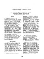
Auxetic materials are fascinating materials
which, when placed under tension in one
direction, become thicker in one or more
perpendicular directions (Figure 1). In other
words, an auxetic material possesses a negative
value of Poisson’s ratio (Evans et al. [1]).
Figure 1. Auxetic material [2].
Recently, numerous investigations on auxetic
materials have been conducted by researchers in
all over the world. The mechanical behaviors
such as static bending, bucking load, dynamic
response and vibration are studied a lot. Shariyat
and Alipour [3] investigated bending and stress
analysis of variable thickness FGM auxetic
conical/cylindrical shells with general tractions
(using first-order shear-deformation theory and
ABAQUS finite element analysis code). The
only published paper on stress analysis of the
auxetic structures was due to Alipour and
Shariyat [4] who developed analytical zigzag
solutions with 3D elasticity corrections for
bending and stress analysis of circular/annular
composite sandwich plates with auxetic cores.
Hou et al. [5] studied the bending and failure
behaviour
of
polymorphic
honeycomb
topologies consisting of gradient variations of
the horizontal rib length and cell internal across
the surface of the cellular structures. The novel
cores were used to manufacture sandwich beams
subjected to three-point bending tests. Full-scale
nonlinear Finite Element models were also
developed to simulate the flexural and failure
behaviour of the sandwich structures.
Auxetic plate and shell structures under blast
load are mainly studied in nonlinear dynamic
91
response and vibration problems. The calculus,
semi-calculus, and numerical methods are
proposed. There are a variety of studies applied
analytical methods including the authors Duc
and Cong [6-10]. In [6-10], the analytical
Reddy’s (first or third) order shear deformation
theory with the geometrical nonlinear in von
Karman and Airy stress functions, Galerkin and
the fourth-order Runge-Kutta methods were
proposed to consider cell of honeycomb core
layer (with NPR). Specifically, the nonlinear
dynamic response of auxetic plate was
conducted in [6], cylinder auxetic shell (within
and without stiffeners) was illustrated in [7,10]
and double curved shallow auxetic shells
(without stiffeners) were mentioned in [8, 9].
From above literature review, in [3-5] the
authors conducted bending and stress analysis
auxetic structures using first-order shear strain
theory and finite element method while in [610], an analytical method and (first or higher)
order shear deformation theory were proposed to
study dynamic response and vibration of auxetic
plate and shell structures.
To the author’s best knowledge, a new thirdorder shear deformation plate theory has not
been used in any published literature yet and it is
also the main motivation of this research work.
It introduces static bending analysis of auxetic
plates with negative Poisson’s ratio using FEM
and a new third-order shear deformation plate
theory. The results show the effects of
geometrical parameters, boundary conditions,
uniform transverse pressure on the static bending
of auxetic plates with negative Poisson’s ratio.
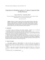
2. Sandwich plate with auxetic core
Considering a sandwich plate with auxetic
core which has three layers in which the top and
bottom outer skins are isotropic aluminum
materials; the central layer has honeycomb
structure using the same aluminum material
(Figure 2a). The bottom outer skin thickness is
h1 , internal honeycomb core material thickness
is h2 and top outer skin thickness is h3 , and the
total thickness of the sandwich plate is
h h1 h2 h3 , as shown in Figure 2b.
P.H. Cong et al. / VNU Journal of Science: Natural Sciences and Technology, Vol. 36, No. 1 (2020) 90-99
92
Figure 2. Model of sandwich plate with auxetic core.
The plate with the auxetic honeycomb core
with negative Poisson’s ratio is introduced in this
paper. Unit cells of core material discussed in the
paper are shown in Figure 2c where l is the
length of the inclined cell rib, hc is the length of
the vertical cell rib, is the inclined angle,
and define the relative cell wall length and the
wall’s slenderness ratio, respectively, which are
important parameters in honeycomb property.
Formulas in reference [11] are adopted for
calculation of honeycomb core material property.
2 E
E1
n33
1 sin
cos 3 1 tan 2 1 sec 2 32
cos 1 tan sec
sin 1
v
tan sin
2
v
12
2
21
2
sin 1 n32 1 sin
2
2
2
1
2
3
2
3
2
2
3
1
3 1 2
2 cos 1 sin
1 h / l,3 t / l .
where symbol “ 2 ” represents core material,
E , G and are Young’s moduli, shear moduli
and mass density of the origin material.
(1)
3. New simple third-order shear deformation
theory of plates
c
3 cos
1 sin
2
3 1 sin 1 2 sin 2
2 cos 1 21
2 1 sin
A finite element formulation based on a new
third-order
shear deformation plate theory,
(
which is originally proposed by Shi in [12], for
static bending analysis of auxetic plates is
derived in this section. This new plate theory, in
which the kinematic of displacements is derived
from an elasticity formulation rather than the
hypothesis of displacements, has shown more
accurate than other higher-order shear
deformation plate theories. The displacements,
n33
2
E2 E
cos 1 sin tan 2 32
33
2
G12 E
1 1 21 cos
G23 G
G13 G
P.H. Cong et al. / VNU Journal of Science: Natural Sciences and Technology, Vol. 36, No. 1 (2020) 90-99
u , v and w at any point of the plate are given
by [12].
5
4 3
u u0 z
z x
4
3h 2
1
5 3
z
z w0,x
3h 2
4
5
4 3
v v0 z
z y
4
3h 2
1
5 3
z
z w0,y
3h 2
4
(2)
w w0
where u0 , v0 , and w0 are respectively the
displacements in the x , y and z directions of a
point on the mid-plane of a plate, while x and
y denote the transverse rotations of a midsurface normal around the x and y axes,
respectively.
Under small strain assumptions, the straindisplacement relations can be expressed as
follows:
x
y 0
1 2 0
xy 0 z
z 2
0
yz
xz
3
z 3
0
in which
u0
x
0 v0
y
v0 u0
y
x
93
x 2 w
5
2
x
x
2
1
y w
1
5
4 y y 2
2
5 x 2 w 5 y
y
x y
x
x 2 w
x 2
x
2
5 y w
3
3h 2 y y 2
2
x 2 w y
y
x y x
w
y
5 y
0
4 w
x
x
w
y
5
2
y
2 w
h
x
x
Based on Hooke's law, the vectors of normal
and shear stresses read
(3)
D z
k
k 0 z1 z 3 3
Dm
k
s
k
0
2
(5)
2
with
(4)
k
k
x
k
y
k
k
yz
xz
Q k
11
k
Q k
Dm
12
0
k
xy
k
T
k
Q12
k
Q22
0
T
0
0
k
Q66
P.H. Cong et al. / VNU Journal of Science: Natural Sciences and Technology, Vol. 36, No. 1 (2020) 90-99
94
Q k
Ds 55
0
2
E
2
Q
1
2 2
1 12 21
11
2
E
2
Q22
3 hk 1
0
k
Q44
2
2 2
1 12 21
(6)
2
,Q
12
12
2
2 2
1 12 21
3 hk 1
,
2
N xy
y
x
xy
T
T
(7a)
0
My
1
M xy
x
y
xy
3 3
T
T
zdz
P Px
Py
Pxy
dz
(7d)
2
2
T
3 hk 1
yz
xz
T
z 2dz
(7e)
k 1 hk
D z z dz
s
k
0
2
2
2
Eqs. (7) can be rewritten in matrix form
0
0
1
0 0
0 0 3
A B 0
B D 2
0
(8)
h/2
A, B, D, E , F , H
T
T
where
k 0 z1 z 3 3 zdz
Dm
k 1 hk
Rx
(7b)
k 1 hk
3 hk 1
0
N A B E
M B D F
E F H
P
Q 0 0 0
R 0 0 0
3 hk 1
xz
k 1 hk
dz
k 1 hk
M Mx
3
T
k
3 hk 1
D z z dz
k
m
3 3
yz
s
k 1 hk
3 hk 1
1
D z dz
R Ry
3 hk 1
z 3dz
k 1 hk
The normal forces, bending moments,
higher-order moments and shear force can then
be computed through the following relations
Ny
3 hk 1
E
1
1
1
, Q66 Q44 Q55
.
2
2
1
1
T
k 1 hk
13
E
N Nx
0
3 hk 1
1
1
k
m
E
2
2 1
1
Q55 G13 , Q11 Q22
,
2
Q12
D z z z dz
Q Qy Qx
, Q66 G12 ,
55
23
xy
k 1 hk
2
2 2
2
Q G ,Q G ,
44
y
x
k 1 hk
2 2
E
2
1, z, z , z , z , z D
2
h/ 2
h/2
(7c)
A, B, D 1, z 2 , z 4 Dsdz
h/2
3
4
6
m dz
P.H. Cong et al. / VNU Journal of Science: Natural Sciences and Technology, Vol. 36, No. 1 (2020) 90-99
The deformation energy of auxetic plate has
the form:
0T
0
0T
1
1 A B
U d
2 0 T E 3
0
1T
B
1T
1
1T
3
D F
3T
0
3T
1
3T
3
E F H
0T
0
0T
2
A B
d
2T
0
2T
2
B D
(9)
In this section, the parameters are selected
as: a 1m, b 1m, h a / 20, h2 3 / 5h,
1 1.8,3 0.0138571.
4.1. Comparison with the results of the isotropic
uniformity calculation
(10)
where K is the stiffness matrix, F is force
vector while d stands for the unknown vector.
We consider a simply-supported and
clamped square plate (side a 1 ) under uniform
transverse pressure ( F 1 ), and thickness h .
The modulus of elasticity is taken E 10,9201 and
the Poisson’s ratio is taken as 0.3 . The nondimensional transverse displacement is set as
ww
D
(13)
Pl 4
where the bending stiffness D is taken as
4. Numerical results and discussion
Both the simply supported and fully clamped
boundary conditions are investigated. For the simply
supported boundary conditions (SSSS) [13]:
v0 w y 0, at x 0, a
(11)
u0 w x 0, at y 0, b
and the fully clamped edges (CCCC) [13]:
u0 v0 w x y 0
w / x w / y 0
at x 0, a and y 0, b
h1 h / 5, E 69GPa, 0.33, 45o ,
For static bending analysis, the bending
solutions can be obtained by solving the
following equation:
Kd F
95
(12)
D
Eh3
12 1 v2
(14)
The results compared with those of Ferreira
[14] are shown in Table 1. In Ref. [14], the
author used the theory of Mindlin plate
considering for the Q4 element. From table 1, it
can be seen a very small difference between 2
studies shows the reliability of the calculation
program.
Table 1. Comparison of non-dimensional transverse displacement of a square plate, under uniform pressuresimply-support (SSSS) and clamped (CCCC) boundary conditions
a/h
Mesh
10
6 6
10 10
20 20
30 30
10,000
6 6
10 10
20 20
30 30
SSSS
Ref. [14]
0.004245
0.004263
0.004270
0.004271
0.004024
0.004049
0.004059
0.004060
Present
0.004429
0.004429
0.004428
0.004428
0.003944
0.004022
0.004055
0.004060
CCCC
Ref. [14]
Present
0.001486
0.001672
0.001498
0.001673
0.001503
0.001673
0.001503
0.001673
0.001239
0.001101
0.001255
0.001208
0.001262
0.001252
0.001264
0.001261
96
P.H. Cong et al. / VNU Journal of Science: Natural Sciences and Technology, Vol. 36, No. 1 (2020) 90-99
4.2. Static bending analysis of auxetic plate
The 20 20 Q4 mesh is used to mesure
static bending analysis of auxetic plate and w is
the deflection at position x 0.5m, y 0.5m.
To study the effect of the geometric
parameters of the plate on the static bending of
the auxetic sheet with a negative Poisson’s ratio,
b / a 0.5,1,2.0 and b / a 0.5,1,2.0 are chosen.
There are 9 different cases of auxetic plate
structures considering 2 types of boundary
conditions: SSSS and CCCC. The results are
illustrated in Table 2. Obviously, with different
boundary conditions and the same value of b / a
the value of deflections w decreases as the
ratio h / a increases (thicker plates) and vice
versa. Whereas, in the case the same value of
h / a , deflections’ value w increase when
increasing b / a and vice versa.
Table 2. Effect of the ratio b / a and on the deflections w of the auxetic plate 21 0.646756
b/a
0.5
1.0
2.0
h/a
0.01
0.05
0.10
0.01
0.05
0.10
0.01
0.05
0.10
Boundary condition
SSSS
0.000136074
1.72466e-006
4.19861e-007
0.000844483
8.60749e-006
1.63836e-006
0.00210822
2.01738e-005
3.44499e-006
CCCC
3.65492e-005
8.6496e-007
3.11035e-007
0.000268721
3.75837e-006
1.01027e-006
0.000537942
6.88992e-006
1.72863e-006
Figure 3. Deformed shape for simply-supported and clamped auxetic plates
and b / a 1, h / a 0.05 and 21 0.646756 .
P.H. Cong et al. / VNU Journal of Science: Natural Sciences and Technology, Vol. 36, No. 1 (2020) 90-99
97
Table 3. Calculation values of the deflections w of the auxetic plate with negative
Poisson’s ratio for different ratios l / h
c
v21
l/h
F 1000Pa, a / h 20, a b
Boundary condition
SSSS
CCCC
0.2
-0.164652
8.67574e-006
3.82713e-006
0.4
-0.394243
8.64811e-006
3.7976e-006
0.6
-0.736624
8.59205e-006
3.74379e-006
0.8
-1.30198
8.49303e-006
3.65204e-006
1
-2.41329
8.31421e-006
3.48954e-006
The analysis of the effect of l / h on the
deflections w of the auxetic plate consider
Table 3, the increasing in l / h leads to decrease
in deflections w .
different values of l / h 0.2,0.4,0.6,0.8,1 . From
Figure 4. The deflections w of auxetic plates.
Figure 4b shows deflections
w
of the
nodes in the diagonal direction of the plate as
shown in Figure 4a. Figure 4 also illustates that
deflections have maximum values at the center
of the plate and in the SSSS boundary condition,
deflections are larger than those in the CCCC
boundary condition.
98
P.H. Cong et al. / VNU Journal of Science: Natural Sciences and Technology, Vol. 36, No. 1 (2020) 90-99
Figure 5. Effect of uniform transverse pressure F Pa on the deflections
w of the auxetic plate
21 0.646756
The effect of uniform transverse pressure on
the deflections w of the auxetic plate
21 0.646756
is presented in Figure 5. It
can be seen that increasing the value of uniform
transverse pressure makes the value of
deflections w and deformed shapes also
increase (shown in Figure 6).
Figure 6. Deformed shape for simply-supported and clamped auxetic plates with value
of uniform transverse pressure F 800Pa and 21 0.646756 .
P.H. Cong et al. / VNU Journal of Science: Natural Sciences and Technology, Vol. 36, No. 1 (2020) 90-99
5. Conclusion
The paper successfully applied finite
element method and a new third-order shear
deformation plate theory to study static bending
of auxetic plate. The calculation results are
compared with other published paper validating
the reliability of the calculation program. Then,
effect of parameters on static bending of auxetic
plates are examined in this paper.
Acknowledgments
This research is funded by Vietnam National
Foundation for Science and Technology
Development (NAFOSTED) under grant
number 107.02-2019.04.
References
[1] K.E. Evans, M. Nkansah, I.J. Hutchison, S.C.
Rogers, Molecular Network Design, Nature 353
(1991) 124-125. doi:10.1038/353124a0.
[2] S. Mohammad, R. Naveen, A. Kim, A. Andrew,
Auxetic materials for sports applications, Procedia
Engineering 72 (2014) 453–458. />1016/j.proeng.2014.06.079.
[3] M. Shariyat, M.M. Alipour, Analytical Bending
and Stress Analysis of Variable Thickness FGM
Auxetic Conical/Cylindrical Shells with General
Tractions, Latin American Journal of Solids and
Structures 14 (2017) 805-843. />1590/1679-78253413.
[4] M.M. Alipour, M. Shariyat, Analytical zigzag
formulation with 3D elasticity corrections for
bending and stress analysis of circular/annular
composite sandwich plates with auxetic cores,
Composite Structures 132 (2015) 175-197. https://
doi.org/10.1016/j.compstruct.2015.05.003.
[5] Y. Hou, Y.H. Tai, C. Lira, F. Scarpa, J.R. Yates, B.
Gu, The Bending and Failure of Sandwich
Structures with Auxetic Gradient Cellular
Cores, Composites Part A: Applied Science and
Manufacturing 49(2013) 119-131. />10.1016/j.compositesa.2013.02.007.
99
[6] N.D. Duc, P.H. Cong, Nonlinear dynamic response
and vibration of sandwich composite plates with
negative Poisson’s ratio in auxetic honeycombs,
Journal of Sandwich Structures and Materials 20(6)
(2018) 692-717. />16674729.
[7] P.H. Cong, P.T. Long, N.V. Nhat, N.D.
Duc, Geometrically nonlinear dynamic response of
eccentrically stiffened circular cylindrical shells
with negative Poisson’s ratio in auxetic
honeycombs core layer, International journal of
Mechanical Sciences 152 (2019) 443-453. https://
doi.org/10.1016/j.ijmecsci.2018.12.052.
[8] P.H. Cong, N.D. Khanh, N.D. Khoa, N.D.
Duc, New approach to investigate nonlinear
dynamic response of sandwich auxetic double
curves shallow shells using TSDT, Compos. Struct.
185 (2018) 455-465. />compstruct.2017.11.047.
[9] N.D. Duc, K.S. Eock, P.H. Cong, N.T. Anh, N.D.
Khoa, Dynamic response and vibration of
composite double curved shallow shells with
negative Poisson’s ratio in auxetic honeycombs
core layer on elastic foundations subjected to blast
and damping loads, International Journal of
Mechanical of Sciences 133 (2017) 504-512. https:
//doi.org/10.1016/j.ijmecsci.2017.09.009.
[10] N.D. Duc, K.S. Eock, N.D. Tuan, P. Tran, N.D.
Khoa, New approach to study nonlinear dynamic
response and vibration of sandwich composite
cylindrical panels with auxetic honeycomb core
layer, Aerosp. Sci. Technol. 70 (2017) 396-404.
/>[11] K. Di, X.B. Mao, Free lexural vibration of
honeycomb sandwich plate with negative Poisson’s
ratio simple supported on opposite edges, Acta
Materiae Compositae Sinica 33 (2016) 910–920.
/>[12] G. Shi, A new simple third-order shear deformation
theory of plates. Int. J. Solids Struct. 44 (2007)
4399-4417. />11.031.
[13] H.T. Hu, B.H. Lin, Buckling optimization of
symmetrically laminated plates with various
geometries and end conditions, Composite Science
and Technology 55 (1995) 277-285. https://doi.
org/10.1016/0266-3538(95)00105-0.
[14] A.J.M Ferreira, Matlab coddes for finite element
analysis. Solids and Structures. Solid Mechanics
and ít applications, Springer, pages: 165-166.