A direct decoder method for OFDM with carrier frequency pilot in underwater acoustic communication systems
Bạn đang xem bản rút gọn của tài liệu. Xem và tải ngay bản đầy đủ của tài liệu tại đây (1.07 MB, 6 trang )
Dinh Hung Do, Quoc Khuong Nguyen
A DIRECT DECODER METHOD FOR OFDM
WITH CARRIER FREQUENCY PILOT IN
UNDERWATER ACOUSTIC COMMUNICATION
SYSTEMS
Dinh Hung Do, Quoc Khuong Nguyen
Hanoi University of Science and Technology, Vietnam
Abstract: In this paper, we propose a new decoder
method at the receiver of system to compensate Doppler
frequency shift for OFDM-based underwater acoustic
communication systems. At the transmitter, in order to
save bandwidth, we do not use additional signal header
(preamble) in each OFDM frame as proposed in many
conventional approaches. Instead, the central subcarrier is reserved for pilot transmission. This
subcarrier is so-called as the carrier frequency pilot
(CFP), which is used to detect the Doppler frequency. At
the receiver, in [1], two synchronization steps are
deployed. The first step, the Doppler frequency is
roughly estimated on the basic of the detected carrier
frequency. In the second step, we use the CFP to
regulate the estimated Doppler frequency. This
regulation is called as fine synchronization. The use of
Doppler compensation scheme in [1] is relatively
complex because in order to calculate Doppler accuracy,
it is necessary to perform two steps. Therefore, I
propose an algebraic computation of Doppler frequency
shift with one step. The results of the Doppler frequency
shift calculation will be used to re-sample the received
signal using the re-sampling matrix. The advance of
using this matrix is that it can be calculated with any
decimal, not an integer such as using the matlab
function available in [1].
Keywords: Underwater Acoustic Communication
(UAC), OFDM, Doppler Frequency Compensation.
I.
INTRODUCTION
With the rapid development of technology, the
underwater acoustic (UWA) communication has been
attracting attention of researchers [2-3]. Compared to
wireless communications, the UWA communications
are more challenging. This is due to the fact that, the
speed of wave propagation of about 1500m/s is much
slower than that of radio waves [3].
The signal bandwidth of an UWA system is usually
less than few tens of kHz.
Thus, to obtain a high data rate in UWA
communications, using modulation scheme with high
spectral efficiency is desirable. In this context, the
Orthogonal frequency division multiplexing (OFDM)
is very promising technique for an effective
transmission rate in a narrow band UWA
communications.
The
multipath
propagation
interference can be combated
by the OFDM technique. However, the penalty of
deploying the OFDM method in UAC is the
sensitivity of the system to the Doppler Effect in
underwater [9]. Any kind of movements in
underwater will introduce an amount of the Doppler
frequency shift, and thus, it will damage the received
OFDM signal. Different to the wireless OFDM
system, the Doppler shift in UAC can be caused by
different sources, such as relative movement of the
transceivers, water surface movement, dynamic chaos
in underwater, etc. The relative ratio of the Doppler
frequency to the carrier spacing of an OFDM-based
UAC is significantly larger than that of the OFDM
radio communication systems. Therefore, the
orthogonally of the OFDM signal will be destroyed. It
results in the ICI. To mitigate the ICI, the Doppler
frequency shift must be compensated at the receiver.
In literature, there are several ICI compensation
approaches for the OFDM-based on UAC [4-6]. The
methods proposed in [4-5] calculate the Doppler shift
after the frequency synchronization. However, in a
case of a large Doppler frequency shift, the
synchronization technique based on a comparison of
the received signal with the transmitted one do not
provide a reliable synchronization result. Thus, the
corresponding estimated Doppler frequency shift is
Corresponding author: Đỗ Đình Hưng,
Email:
Manuscript received: 6/2018, revised: 8/2018, accepted: 8/2018.
SỐ 03 (CS.01) 2018
TẠP CHÍ KHOA HỌC CÔNG NGHỆ THÔNG TIN VÀ TRUYỀN THÔNG
21
A DIRECT DECODER METHOD FOR OFDM WITH CARRIER FREQUENCY PILOT …
also inaccurate. This is our motivation to propose a
Doppler frequency estimation method, which does not
rely on the preamble or the postamble signal as done
in [4].
In the proposed method, the Doppler frequency is
estimated before the OFDM signal is synchronized. In
order to estimate the Doppler frequency, subcarrier is
reserved to be used as a reference frequency. This
subcarrier is called as the CFP (Carrier Frequency
Pilot). The CFP is increased higher amplititude than
the other subcarriers, and it can be used both for
Doppler frequency and channel estimation.
S [S0 , S1 ,..., SK 1 ]
(1)
where K is the number of the data symbols which
are modulated to an OFDM symbol. K is selected to
be less than a half of the FFT length, namely:
K N 1 , where N FFT 2 N 1 denotes the FFT
length. This is to server later on purpose of using a
data symbol with zeros mapping, as shown in Fig. 3,
to avoid the use of an I/Q modulator in the UWA
communication systems. In UWA communications,
ones prefer to use a low carrier frequency of about
several tens of kHz. This is to avoid high attenuation
at high frequency [10]. Because the acoustic signal is
low frequency signal, it is not necessary to use the I/Q
modulator to convert the signal in baseband to
bandpass.
For an example, if the desired frequency range is
from f min 20kHz to f max 28kHz , the sampling
frequency f s 96kHz . The signal S are then inserted
with ( N 1 L2 ) zeros in the front, and in the end to
form signal X
of N FFT samples.
Fig. 1. The block structure of underwater system
To compensate the Doppler frequency shift, we
need only one step to estimated Doppler shift. This is
quite different from the other proposed method [3-5].
To estimate Doppler frequency shift, we use CFP as a
carrier frequency so when we detect the CFP in
receiver signal we also calculate receiver frequency
therefore Doppler shift will be estimated. Compared
to the technique proposed in [4], our method does not
need a long frame, it can be worked with very short
frame even with one or two symbol per frame,
however with longer frame our method will get more
accurately Doppler shift. Therefore, our approach can
be applied to a very fast time-varying channel, where
the relative movement speed of the transceivers is
high. The drawn back of our method is increase the
transmitting power of OFDM signal. In practical,
compare to the case of OFDM signal without using
CFP, OFDM with CFP signal makes increasing 10
percent power of OFDM transmitted signal.
This paper is organized as follows: Section I is
Introduction, Section II describes the proposed
architecture of an acoustic OFDM system and the
proposed method for compensating the Doppler
frequency shift. Section III is the experimental results
of the system using our method and discussion.
Section IV concludes the paper.
II. SYSTEM DESCRIPTION
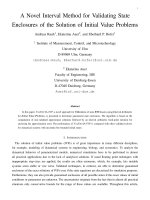
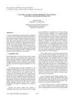
A. Transmitter structure
The diagram of our proposed OFDM system is
shown in Fig. 1(A), where the input data bits are split
to K parallel outputs by a serial/parallel (S/P)
converter. The bit stream on K parallel outputs are
modulated to complex symbols by using the M-QAM
scheme. The modulated symbols within an OFDM
symbol are denoted by:
SỐ 03 (CS.01) 2018
Fig. 2. Zeros Insertion
X [0,...,0, S0 ,..., SK 1 ,0,...,0, SK* 1 ,..., S0* ,0,...,0] (2)
The
distance between OFDM subcarriers:
f f s / (2 N ) . So in Fig. 2, L1 f min / f and
L2 f max / f
are respectively the start and the end
of data subcarriers to the position of S 0 and S K 1 .
After the mapping block, signal entered an inverse
fast fourier transforms (IFFT) block after mapping
block, outputs composed of the real signal x(n) in the
time domain. The last GI samples of x(n) are copied
and padded in front of itself to deal with intersymbol
interference (ISI). Then they are converted into the
parallel to serial (P/S) converter and the last enter
digital to analog converter (DAC) connect to
transducer, in here the signal is carried by acoustic
waves. In the receiver side, the signal will be decoded
OFDM with reverse sequence. The concept of using
the CFP for Doppler frequency estimation is deployed
on the subcarrier at the central of the system
bandwidth, which corresponds to the subcarrier index
( L1 K / 2) or the subcarrier frequency:
Fc f ·( L1
K
)
2
(3)
In order to estimate channel at receiver side, Pilot
will be inserted into data S . Fig. 3 show Pilot and
TẠP CHÍ KHOA HỌC CÔNG NGHỆ THÔNG TIN VÀ TRUYỀN THÔNG
22
Dinh Hung Do, Quoc Khuong Nguyen
Data are inserted together. Because this is very fast
moving system so we use continuous Pilot in
frequency domain. To overcome the noise and
interference in UW communication, the amplitude of
the CFP signal Ac should be boosted with higher
amplitude in comparison with the other normal Pilot
and data signal.
y(n) h(n)* x(n) w(n)
(5)
where h(n) is the impulse response function and
w(n) is the additive noise.
The receiver signal in time domain is vector:
y [ y0 , y1 ,..., yLF ] where LF is length of
receiving frame. Length of receiving frame can
include all frame and zeros insertion at the head and
tail of each frame. The received signal in frequency
domain: Y [Y0 , Y1 ,..., YLF ] can be calculated
through discrete Fourier transform FFT: Y F ( y)
where F is Fourier transformed. CFP Fr at the
receiver is calculated based on half length of
according to the formula:
Fig. 3. Data and Pilot Insertion
The increased power when using CFP ( Pwith _ CFP )
compare with the case without using CFP
( Pwithout _ CFP ) can be calculated as follow:
A2 A2
·100% 1 c 2 ·100% (4)
Pwithout _ CFP
K·A
Pwith _ CFP
Fr
The different sampling
transmitter and receiver is:
f
where A 2·( M 1) / 3 is avergage amplitude of
M-QAM modulation. In our experiment, Ac 6 ,
M 4 , K 174 then the power will be increased
10 percent.
Fig. 4 show Frame Structure (a) and OFDM
Transmitting Signal Spectrum (b). We organize
OFDM frame contain N s OFDM symbols, zeros gap
is used to separate frames. The length of zeros is
show in Table I.
Td
arg(max Y (1: LF / 2) )· f s
LF
where
frequency
( Fc Fr )· f s
Fc
Y
(6)
between
(7)
Fc is real frequency at CFP at transmitted
side.
Transmitted sampling frequency at receiver side
will be recalculated:
fˆs f s f
(8)
Based on zeros gap between two frames so we can
detect the start of each frame through Start Frame
detection Block in receiver scheme Fig. 1(B). So total
length in samples of each OFDM frame LˆF at
receiver is:
LˆF N s Nˆ
where
(9)
N s is number of OFDM symbols per frame.
Nˆ is length in number of samples of OFDM
symbols at receiver:
( N GI )· f s
Nˆ FFT
fˆs
(10)
All OFDM symbols in each frame will be separate
individual based on its correspondent length at
receiver. After remove GI, each OFDM is vector with
length Nˆ : vNˆ 1 [v0 , v1 ,..., vNˆ ] .
Fig. 4. Data and Pilot
B. Receiver structure
Fig.1(B) shows the receiver structure embedded
our algorithm of Doppler frequency estimation and
compensation. The discrete received signal at the
receiver y (n) can be represented as:
SỐ 03 (CS.01) 2018
Those symbols will be put through resampled
matrix G RS :
v G RS v
where
(11)
G RS is resampled matrix with size N Nˆ .
TẠP CHÍ KHOA HỌC CÔNG NGHỆ THÔNG TIN VÀ TRUYỀN THÔNG
23
A DIRECT DECODER METHOD FOR OFDM WITH CARRIER FREQUENCY PILOT …
G RS is created from G RS matrix with size
th
N ( Nˆ 2·L 1) . The rows i of G RS is g i :
gi 0..0, g ( LT ti ),.., g (ti ),.., g ( LT ti ), 0..0
Nˆ - 1
1
2·L 1
(12)
where
L is length of g (t ) filter, i 1..Nˆ
i· f
ti s
fˆ
(13)
s
i· f
s
fˆs
(14)
mean transmitter moves far from receiver and plus
sign is in opposition direction. At maximum speed of
3.5m / s the Doppler frequency shift is about
56Hz to 56Hz compare with CFP at 24kHz ,
this frequency shift is greater than the width of a
subcarrier of the OFDM signal is 46.865Hz . Fig. 6
show real signal at receiver in time and frequency
domain obtain from experiment in the case of moving
transmitter far away from receiver and come back
again. Transmitting parameter of OFDM system is
showed in Table I.
Then the results were processed by the software,
which was developed by the Wireless Communication
Laboratory of HUST. The OFDM system parameters
are shown in Table I.
Table I. The OFDM system Parameters
G RS is extracted from column L 1 to Nˆ L of
Parameter
1 Transmitter- 1 Receiver
Frequency sampling (kHz)
Bandwidth (kHz)
G RS matrix. Here, g (t ) is pulse sharping raised
cosin function [12], g (t ) is show in equation as
follow:
g (t )
sin( t / T ) cos( t / T )
t / T 1 4 2t 2 / T 2
FFT length ( N FFT )
(15)
Guard interval length (GI)
Multilever modulation
After resample to N length, signals v will go
through FFT block and Channel estimation to
recovery data.
OFDM symbol/Frame ( Ts ) (ms)
The distance between OFDM
subcarries ( F ) (Hz)
Number of OFDM symbol/Frame
Value
SISO
96
20-28
2048
1024
M-QAM
32
46.865
30
( Ns )
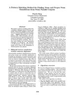
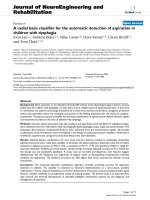
III. EXPERMENTAL AND RESULTS
The underwater experiments were carried out at
Hotien lake at Hanoi University of Science and
Technology (HUST).The experiment setup is
illustrated in Fig. 5. In this experiment, the receiver is
set at the fixed location beside the lake. The
transmitter is on the small boat which is towed by
rope from both side in right direction toward the
receiver.
Frame length (ms)
Roll-off factor raised cosin filter
( )
Amplitude of CFP
Amplitude of normal pilot
Time gap between frames ( Td )
960
0.2
6
1.4142
150
(ms)
Length of g (t ) in sample
15
The signals were modulated by M-QAM, with N FFT
= 2048, the guard interval length is 1024. The system
bandwidth is from 20kHz to 28kHz .
Signals are transmitted consecutive frames separated
by about 0.15s . Each frame consists of OFDM
Fig.5. Illustration of the experimental setup in Hotien Lake
Then the results were processed by the software,
which was developed by the Wireless Communication
Laboratory of HUST. The OFDM system parameters
are shown in Table I. The signals were modulated by
M-QAM, with N FFT = 2048, the guard interval (GI)
length is: 1024. The system bandwidth is from
20kHz to 28kHz . Signals are transmitted
consecutive frames separated by about 0.15s . Each
frame consists of OFDM symbols N s . In our
symbols
N s . In our experiment, the range of speed
change maximum from 3.5m / s to 3.5m / s . Minus
sign of speed mean transmitter moves far from
receiver and plus sign is in opposition direction.
At maximum speed of 3.5m / s the Doppler
frequency shift of about 56Hz to 56Hz compare
with CFP at 24kHz , this frequency shift is greater
than the width of a subcarrier of the OFDM signal is
46.865Hz .
experiment, the range of speed change maximum
from 3.5m / s to 3.5m / s . Minus sign of speed
SỐ 03 (CS.01) 2018
TẠP CHÍ KHOA HỌC CÔNG NGHỆ THÔNG TIN VÀ TRUYỀN THÔNG
24
Dinh Hung Do, Quoc Khuong Nguyen
without having to round and recalculate as in the
method in [1], thus saving time calculating and
proactively designing programmatic systems without
the need for matlab based programming.
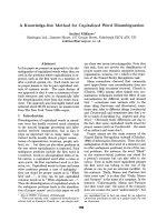
Fig. 6. Receiving signal in time domain and spectrum of
receiving signal
In Fig. 6 the real signal at receiver in time and
frequency domain obtain from experiment in the case
of moving transmitter far away from receiver and
come back again.
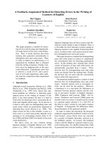
Fig. 7. Changing Doppler and equivalence Speed in
experiment
IV. CONCLUTIONS
OFDM is promising technique in combating
multipath channel and high Doppler frequency shift in
Underwater communication. Proposed method has
solved doppler shift problems through using OFDM
Pilot as a carrier frequency pilot (CFP). Advantages
of proposed method is increasing bandwidth
efficiency of system because it doesn't add extra
frame structure or special signals to the OFDM signal
frame.
The advantage of direct decoder is simpler in
calculation because only one step is required to
accurately calculate Doppler frequency.
The disadvantage proposal method is increasing
the transmitting power. However, using our method
can solve the quick speed changing between
transmitter and receiver through using short frame. So,
our proposed method can handle with uniform
Doppler distribution. Despite this method can apply
for moving system with speed of hundreds meters per
second in simulation with computer but in the
experiment results just deployed on the campus of the
University should be in the test speed restrictions is
3.5m / s .
ACKNOWLEDGMENTS
This research was supported by HaNoi University
of Science and Technology under the project T2016LN-14.
REFERENCES
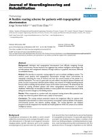
Fig. 7 is estimated Doppler frequency shift and
correspondent speeds obtain from experiment.
The maximum velocity is 3.5m / s corresponding to a
frequency offset of 56Hz , and the acceleration rate is
about 2m / s / s .
Fig. 8. Symbols Error Rate (SER) on receiving frames
Symbols Error Rate (SER) from frame to frame
is shown in Fig. 8, that is obtained without using error
code correction.
The results in Figure 8 indicate that the new
decoding method gives a slightly better quality than
the old one. However, the advantages of this method
are simpler in calculation because only one step is
required to accurately calculate Doppler frequency
SỐ 03 (CS.01) 2018
[1] Quoc Khuong Nguyen, Dinh Hung Do and Van Duc
Nguyen, Doppler Compensation Method using Carrier
Frequency Pilot for OFDM-Based Underwater
Acoustic Communication System, 2017 International
Conference
on Advanced
Technologies
for
Communication, pp. 254-259, Oct 2017.
[2] P. A. van Walree, Propagation and scattering effects in
underwater acoustic communication channels, IEEE
Journal of Oceanic Engineering, vol. 38, no. 4, pp.
614-631, 2013.
[3] M. Stojanovic and J. Preisig, Underwater acoustic
communication channels: Propagation models and
statistical characterization, IEEE Communications
Magazine, vol. 47, no. 1, pp. 84-89, jan 2009.
[4] Tran Minh Hai, Saotome Rie, Suzuki Taisuki,
Tomohisa Wada, A Transceiver Architecture for
Ultrasonic
OFDM
with
Adaptive
Doppler
Compensation, International Journal of Information
and Electronics Engineering, vol. 4, no. 3, 2014.
[5] B. Li, S. Zhou, M. Stojanovic, L. Freitag, and P.
Willett, Non-uniform Doppler compensation for zeropadded OFDM over fast-varying underwater acoustic
channels, in OCEANS 2007-Europe. IEEE, pp.1-6,
2007.
[6] Baosheng Li, Student Member, IEEE, Shengli Zhou,
Member, IEEE, Milica Stojanovic, Member, IEEE,
Lee Freitag, Member, IEEE, and Peter Willett, Fellow,
IEEE Multicarrier Communication over Underwater
Acoustic Channels with Nonuniform Doppler Shifts
IEEE Journal of Oceanic Engineering, vol. 38, no. 4,
pp. 614-631, 2013.
TẠP CHÍ KHOA HỌC CÔNG NGHỆ THÔNG TIN VÀ TRUYỀN THÔNG
25
A DIRECT DECODER METHOD FOR OFDM WITH CARRIER FREQUENCY PILOT …
[7] M.Stojanovic,Low complexity OFDM detector for
underwater acoustic channels, IEEE Oceans Conf.,
Sept. 2006.
[8] Hai Minh Tran, Tomohisa Wada , On ICI Canceller for
Mobile OFDM DTV Receivers, TACT vol. 2, pp. 290297, 2013.
[9] A. B. Awoseyila, C. Kasparis, and B. G. Evans,
Improved preambleaided timing estimation for OFDM
systems, IEEE Communications Letters, vol. 12, no.
11, pp. 825-827, 2008.
[10] J. A. Hildebrand, Anthropogenic and natural sources of
ambient noisein the ocean, Marine Ecology Progress
Series, vol. 395, pp. 5-20, 2009.
[11] T. Schmidl and D. Cox, Robust frequency and timing
synchronization for OFDM, IEEE Trans. Commun,
vol. 45, no.12, pp. 1613-1621, 1997.
[12] T.Kang and R. Iltis, " Fast-varying doppler
compensation for underwater acoustic OFDM
systems" in Proc. IEEE Asilomar Conf. on Signals,
Systems and Computers, Oct. 2008, pp. 933-937.
Đỗ Đình Hưng học
viên Tiến sỹ từ năm
2015,
Hiện công
tác tại Khoa Công
nghệ Điện tử thông
tin. Lĩnh vực nghiên
cứu: Kỹ thuật xử lý
tín hiệu và truyền
thông tin thủy âm sử
dụng các hệ thống
thu phát một hoặc
nhiều anten.
Nguyễn
Quốc
Khương nhận học vị
Tiến sỹ năm 2011,
Hiện công tác tại
Trường Đại học
Bách Khoa – Hà
Nội. Lĩnh vực nghiên
cứu: Kỹ thuật xử lý
tín hiệu và truyền
thông vô tuyến, hữu
tuyến và truyền
thông tin thủy âm sử
dụng các hệ thống
thu phát một hoặc
nhiều anten.
SỐ 03 (CS.01) 2018
TẠP CHÍ KHOA HỌC CÔNG NGHỆ THÔNG TIN VÀ TRUYỀN THÔNG
26