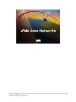
Wireless Local Area Networks
Bạn đang xem bản rút gọn của tài liệu. Xem và tải ngay bản đầy đủ của tài liệu tại đây (371.12 KB, 34 trang )
9
Wireless Local Area Networks
9.1 Introduction
The growth of Wireless Local Area Network (WLANs) commenced in the mid-1980s and
was triggered by the US Federal Communications Commission (FCC) decision to authorize
the public use of the Industrial, Scientific and Medical (ISM) bands. This decision eliminated
the need for companies and end users to obtain FCC licenses to operate their wireless
products. Since then, there has been a substantial growth in the area of WLANs. Lack of
standards, however, enabled the appearance of many proprietary products thus dividing the
market into several, possibly incompatible parts. Consequently, the need for standardization
in the area appeared.
The first attempt to define a standard was made in the late 1980s by IEEE Working Group
802.4, which was responsible for the development of the token-passing bus access method.
The group decided that token passing was an inefficient method to control a wireless network
and suggested the development of an alternative standard. As a result, the Executive Commit-
tee of IEEE Project 802 decided to establish Working Group IEEE 802.11 which has been
responsible since then for the definition of physical and MAC sublayer standards for WLANs.
The first 802.11 standard was finalized in 1997 and was developed by taking into considera-
tion existing research efforts and market products, in an effort to address both technical and
market issues. It offered data rates up to 2 Mbps using spread spectrum modulation in the ISM
bands. In September 1999, two supplements to the original standard were approved by the
IEEE Standards Board. The first standard, 802.11b, extends the performance of the existing
2.4 GHz physical layer, with potential data rates up to 11 Mbps. The second, 802.11a, aims to
provide a new, higher data rate (from 20 up to 54 Mbps) physical layer in the 5 GHz band.
The family of 802.11 standards is shown in Figure 9.1.
In addition to IEEE 802.11, another WLAN standard, High Performance European Radio
LAN (HIPERLAN), was developed by group RES10 of the European Telecommunications
Standards Institute (ETSI), as a Pan-European standard for high speed WLANs. The HIPER-
LAN 1 standard, like 802.11, covers the physical and MAC layers, offering data rates
between 2 and 25 Mbps by using traditional radio modulation techniques in the 5.2 GHz
band. Upon completion of the HIPERLAN 1 standard, ETSI decided to merge the work on
Radio Local Loop and Radio LANs through the formation of Broadband Radio Access
Networks (BRAN). This project aims to specify standards for Wireless ATM (HIPERLAN
Types 2, 3, 4). The family of HIPERLAN standards is shown in Figure 9.2.
9.1.1 Benefits of Wireless LANs
The continual growth in the area of WLANs can be partly attributed to the need to support
mobile networked applications. Many jobs nowadays require people to physically move
while using an appliance, such as a hand-held PC, which exchanges information with
other user appliances or a central computer. Examples of such jobs are healthcare workers,
police officers and doctors. Wired networks require a physical connection between the
communicating parties, a fact that poses great difficulties in the implementation of practical
equipment. Thus, WLANs are the technology of choice for such applications.
Another benefit of using a WLAN is the reduction in infrastructure and operating costs. A
wireless LAN needs no cabling infrastructure, significantly lowering its overall cost. More-
over, in situations where cabling installation is expensive or impossible (e.g. historic build-
ings, monuments or the battlefield) WLANs appear to be the only feasible means to
implement networking. Lack of cabling also means reduced installation time, a fact that
drives the overall network cost even lower.
A common fact in wired networks is the problems that arise from cable faults. Cable faults
are responsible for most wired network failures. Moisture which causes erosion of the metal-
lic conductors and accidental cable breaks can bring a wired network down. Therefore, the
use of WLANs helps reduce the downtime of the network and eliminates the costs associated
with cable replacement.
9.1.2 Wireless LAN Applications
The four major areas for WLAN applications [1] are LAN extension, cross-building inter-
connection, nomadic access and ad hoc networking. In the following sections we briefly
examine each of these areas.
As mentioned, early WLAN products aimed to substitute wired LANs. A WLAN reduces
installation costs by using less cable than a wired LAN. However, with advances in data
transmission technology, companies continue to rely on wired LANs, especially those that
use category 3 unshielded twisted pair cable. Most existing buildings are already wired with
this type of cabling and new buildings are designed by taking into account the need for data
Wireless Networks240
Figure 9.1 The IEEE 802.11 family of standards
Figure 9.2 The ETSI HIPERLAN family of standards
applications and are thus pre-wired. As a result, WLANs were not able to substitute their
wired counterparts to any great extent. However, they were found to be suitable in cases were
flexible extension of an existing network infrastructure was needed. Examples include manu-
facturing plants, warehouses, etc. Most of these organizations already have a wired LAN
deployed to support servers and stationary workstations. For example, a manufacturing plant
typically has a factory floor, where cabling is not present, which must be linked to the plant’s
offices. A WLAN can be used in this case to link devices that operate in the uncabled area to
the organization’s wired network. This application area of WLANs is referred to as LAN
extension.
Another area of WLAN application is nomadic access. It provides wireless connectivity
between a portable terminal and a LAN hub. One example of such a connection is the case of
an employee transferring data from his portable PC to the server in his office upon returning
from a trip or meeting. Another example of nomadic access is the case of a university campus,
where students and working personnel access applications and information offered by the
campus through their portable computers.
Ad hoc networking is another area of WLAN use. An ad hoc network is a peer-to-peer
network that is set up in order to satisfy a temporary need. An example of this kind of
application is a conference room or business meeting where the attendants use their portable
computers in order to form a temporary network in order to share information during the
meeting.
Another use of WLAN technology is to connect wired LANs located in nearby buildings. A
point-to-point wireless link controlled by devices that usually incorporate a bridge or router
functionality, connects the wired LANs. Although this kind of application is not really a
LAN, it is often included in the area of WLANs.
9.1.3 Wireless LAN Concerns
The primary disadvantage of wireless medium transmission, compared to wired transmission,
is its increased error rate. The wireless medium is characterized by Bit Error Rates (BERs)
having an order of magnitude even up to ten times the order of magnitude of a LAN cable’s
BER. The primary reason for the increased BER is atmospheric noise, physical obstructions
found in the signal’s path, multipath propagation and interference from other systems. The
latter takes either an inward or outward direction.
Inward interference comes from devices transmitting in the frequency spectrum used by
the WLAN. However, most WLANs nowadays implement spread spectrum modulation,
which operates over a wide amount of bandwidth. Narrowband interference only affects
part of the signal, thus causing just a few errors, or no errors at all, to the spread spectrum
signal. On the other hand, wideband interference, such as that caused by microwave ovens
operating in the 2.4 GHz band, can have disastrous effects on any type of radio transmission.
Interference is also caused by multipath fading of the WLAN signals, which results in random
phase and amplitude fluctuations in the received signal. Thus, precautions must be taken in
order to reduce inward interference in the operating area of a WLAN. A number of techniques
that operate either on the physical or MAC layer (like alternative modulation techniques,
antenna diversity and feedback equalization in the physical layer, Automatic Repeat Requests
(ARQ), Forward Error Control (FEC) in the MAC sublayer) are often used in this direction.
Outward interference occurs when the WLAN signals disrupt the operation of adjacent
Wireless Local Area Networks 241
WLANs or radio devices, such as intensive care equipment or navigational systems.
However, as most WLANs use spread spectrum technology, outward interference is consid-
ered insignificant most of the time.
A significant difference between wired and wireless LANs is the fact that, in general, a
fully connected topology between the WLAN nodes cannot be assumed. This problem gives
rise to the ‘hidden’ and ‘exposed’ terminal problems, depicted in Figure 9.3. The ‘hidden’
terminal problem describes the situation where a station A, not in the transmitting range of
another station C, detects no carrier and initiates a transmission. If C was in the middle of a
transmission, the two stations’ packets would collide in all other stations (B) that can hear
both A and C. The opposite of this problem is the ‘exposed’ terminal scenario. In this case, B
defers transmission since it hears the carrier of A. However, the target of B, C, is out of A’s
range. In this case B’s transmission could be successfully received by C, however, this does
not happen since B defers due to A’s transmission.
Another difference between wired and wireless LANs is the fact that collision detection is
difficult to implement. This is due to the fact that a WLAN node cannot listen to the wireless
channel while sending, because its own transmission would swamp out all other incoming
signals. Therefore, use of protocols employing collision detection is not practical in WLANs.
Another issue of concern in WLANs is power management. A portable PC is usually
powered by a battery having a finite time of operation. Therefore, specific measures have
to be taken in the direction of minimizing energy consumption in the mobile nodes of the
WLAN This fact may result in trade-offs between performance and power conservation.
The majority of today’s applications communicate using protocols that were designed for
wire-based networks. Most of these protocols degrade significantly when used over a wireless
link. TCP for example was designed to provide reliable connections over wired networks. Its
efficiency, however, substantially decreases over wireless connections, especially when the
WLAN nodes operate in an area where interference exists. Interference causes TCP to lose
connections thus degrading network performance.
Another difference between wired and wireless LANs has to do with installation. When
preparing for a WLAN installation one must take into account the factors that affect signal
propagation. In an ordinary building or even a small office, this task is very difficult, if not
impossible. Omnidirectional antennas propagate a signal in all directions, provided that no
obstacle exists in the signal’s path. Walls, windows, furniture and even people can signifi-
cantly affect the propagation pattern of WLAN signals causing undesired effects. MOST of
the time, this problem is addressed by performing propagation tests prior to the installation of
WLAN equipment.
Security is another area of concern in WLANs. Radio signals may propagate beyond the
geographical area of an organization. All a potential intruder has to do is to approach the
WLAN operating area and with a little bit of luck eavesdrop on the information being
exchanged. Nevertheless, for this scenario to take place, the potential intruder needs to
Wireless Networks242
Figure 9.3 Terminal scenarios: (a) ‘hidden’’ and (b) ‘exposed’
possess the network’s access code in order to join the network. Encryption of traffic can be
used to increase security, which, however, has the undesired effect of increased cost and
overhead. WLANs are also susceptible to electronic sabotage. Most of them utilize CSMA-
like protocols where all nodes are obliged to remain silent as long as they hear a transmission
in progress. If someone sets a node within the WLAN area to endlessly transmit packets, all
other nodes are prevented from transmitting, thus bringing the network down.
Finally, a popular issue that has to do not only with WLANs, but also with wireless
communications in general, is human safety. Despite the fact that a final answer to this
question has yet to be given, WLANs appear to be, in the worst case, just as safe as cellular
phones. Radio-based WLAN components operate at power levels between 50 and 100 mW,
which is substantially lower than the 600 mW to 3 W range of a common cellular phone. In
infrared WLAN systems, the threat to human safety is even lower. Diffused Infrared (IR)
WLANs offer no hazard under any circumstance.
9.1.4 Scope of the Chapter
The remainder of this chapter provides an overview of the WLAN area. In Section 9.2 the two
types of WLAN topologies, infrastructure and ad hoc, are investigated. In Section 9.3 the
requirements a WLAN is expected to meet are discussed. These requirements impact the
implementation of physical and MAC layers for WLANs. In Section 9.4, physical layer
matters are investigated and the five technology alternatives used today are presented. In
Section 9.5 MAC sublayer issues are discussed and the two existing WLAN standards, IEEE
802.11 and HIPERLAN 1, are examined. Section 9.6 presents the latest developments in the
WLAN area. The chapter ends with a brief summary in Section 9.7.
9.2 Wireless LAN Topologies
There are two major WLAN topologies, ad hoc and infrastructure (Figure 9.4). An ad hoc
WLAN is a peer-to-peer network that is set up in order to serve a temporary need. No
networking infrastructure needs to be present, as the only things needed to set up the
WLAN are the mobile nodes and use of a common protocol. No central coordination exists
in this topology. As a result, ad hoc networks are required to use decentralized MAC proto-
cols, such as CSMA/CA, with all nodes having the same functionality and thus implementa-
tion complexity and cost. Moreover, there is no provision for access to wired network
Wireless Local Area Networks 243
Figure 9.4 WLAN topologies: ad hoc and infrastructure
services that may be collocated in the geographical area in which the ad hoc WLAN operates.
Another important aspect of ad hoc WLANs is the fact that fully connected network topol-
ogies cannot be assumed [2]. This is due to the fact that two mobile nodes may be temporarily
out of transmission range of one another.
An infrastructure WLAN makes use of a higher speed wired or wireless backbone. In such
a topology, mobile nodes access the wireless channel under the coordination of a Base Station
(BS). As a result, infrastructure-based WLANs mostly use centralized MAC protocols like
polling, although decentralized MAC protocols are also used (For example, the contention-
based 802.11 can be implemented in an infrastructure topology). This approach shifts imple-
mentation complexity from the mobile nodes to the Access Point (AP), as most of the
protocol procedures are performed by the AP thus leaving the mobile nodes to perform a
small set of functions. The mobile nodes under the coverage of a BS, form this BS’s cell.
Although a fully connected network topology cannot be presumed in this case either, the fixed
nature of the BS implies full coverage of its cell in most cases. Traffic that flows from the
mobile nodes to the BS is called uplink traffic. When the flow of traffic follows the opposite
direction, it is called downlink traffic.
Another use of the BS is to interface the mobile nodes to an existing wired network. When
a BS performs this task as well, it is often referred to as an Access Point (AP). Despite the fact
that it is not mandatory that the BS and AP be implemented in the same device, most of the
time BSs also include AP functionality. Providing connectivity to wired network services is
an important requirement, especially in cases where the mobile nodes use applications
originally developed for wired networks.
The presence of many BSs and thus cells is common in infrastructure WLANs. Such
multicell configurations can cover multiple-floor buildings and are employed when greater
range than that offered by a single cell is needed. In this case, mobile nodes can move from
cell to cell while maintaining their logical connections. This procedure is also known as
roaming and implies that cells must properly overlap so that users do not experience connec-
tion losses. Furthermore, coordination among access points is needed in order for users to
transparently roam from one cell to another. Roaming is implemented through handoff
procedures. Handoff can be controlled either by a switching office in a centralized way, or
by mobile nodes (decentralized handoff) and is implemented by monitoring the signal
strengths of nodes. In centralized handoff, the BS monitors the signal strengths of the mobile
nodes and reassigns them to cells accordingly. In decentralized handoff, a mobile node may
decide to request association with a different cell after determining that link quality to that
cell is superior to that of the previous one.
As far as the cell size is concerned, it is desirable to use small cells. Reduced cell sizes
means shorter transmission ranges for the mobile nodes and thus less power consumption.
Furthermore, small cell sizes enable frequency reuse schemes, which result in spectrum
efficiency. The concept of frequency reuse is illustrated in Figure 9.5. In this example,
nonadjacent cells can use the same frequency channels. If each cell uses a channel with
bandwidth B, then with frequency reuse, a total of 3 £ B bandwidth is sufficient to cover
the 16-cell region. Without frequency reuse, every cell would have to use a different
frequency channel, a scheme that would demand a total 16 £ B of bandwidth.
The above strategy is also known as Fixed Channel Allocation (FCA). Using FCA, chan-
nels are assigned to cells and not to mobiles nodes. The problem with this strategy is that it
does not take advantage of user distribution. A cell may contain a few, or no mobiles nodes at
Wireless Networks244
all and still use the same amount of bandwidth as a densely populated cell. Therefore,
spectrum utilization is suboptimal. Dynamic channel allocation (DCA) [3–5], Power Control
(PC) or integrated DCA and PC [6] techniques try to increase overall cellular capacity, reduce
channel interference and conserve power at the mobile nodes. DCA places all available
channels in a common pool and dynamically assigns them to cells depending on their current
load. Furthermore, the mobile nodes notify BSs about experienced interference enabling
channel reuse in a way that minimizes interference. PC schemes try to minimize interference
in the system and conserve energy at the mobile nodes by varying transmission power. When
increased interference is experienced within a cell, PC schemes try to increase the Signal to
Interference noise Ratio (SIR) at the receivers by boosting transmission power at the sending
nodes. When the interference experienced is low, sending nodes are allowed to lower their
transmitting power in order to preserve energy.
Comparison of the above two WLAN topologies yields several differences [7]. However,
most of these results stem from the assumption that ad hoc WLANs utilize contention MAC
protocols (e.g. CSMA) whereas infrastructure networks use TDMA-based protocols. Based
solely on topology, one can argue that the main advantage of infrastructure WLANs is their
ability to provide access to wired network applications and services. On the other hand, ad
hoc WLANs are easier to set up and require no infrastructure, thus having potentially lower
costs.
9.3 Wireless LAN Requirements
A WLAN is expected to meet the same requirements as a traditional wired LAN, such as high
capacity, robustness, broadcast and multicast capability, etc. However, due to the use of the
wireless medium for data transmission, there are additional requirements to be met. Those
requirements affect the implementation of the physical and MAC layers and are summarized
below:
†
Throughput. Although this is a general requirement for every network, it is an even more
Wireless Local Area Networks 245
Figure 9.5 Example of frequency reuse
crucial aspect for WLANs. The issue of concern in this case is the system’s operating
throughput and not the maximum throughput it can achieve. In a wired 802.3 network, for
example, although a peak throughput in the area of 8 Mbps is achievable, it is accom-
panied by great delay. Operating throughput in this case is measured to be around 4 Mbps,
only 40% of the link’s capacity. Such a scenario in today’s WLANs with physical layers of
a couple of Mbps, would be undesirable. Thus, MAC sublayers that shift operating
throughput towards the theoretical figure are required.
†
Number of nodes. WLANs often need to support tens or hundreds of nodes. Therefore the
WLAN design should pose no limit to the network’s maximum number of nodes.
†
Ability to serve multimedia, priority traffic and client server applications. In order to serve
today’s multimedia applications, such as video conferencing and voice transmission, a
WLAN must be able to provide QoS connections and support priority traffic among its
nodes. Moreover, since many of today’s WLAN applications use the client-server model, a
WLAN is expected to support nonreciprocal traffic. Consequently, WLAN designs must
take into consideration the fact that flow of traffic from the server to the clients can often be
greater than the opposite.
†
Energy saving. Mobile nodes are powered by batteries having a finite time of operation. A
node consumes battery power for packet reception and transmission, handshakes with BSs
and exchange of control information. Typically a mobile node may operate either in
normal or sleep mode. In the latter case, however, a procedure that wakes up a transmis-
sion’s destination node needs to be implemented. Alternatively, buffering can be used at
the sender, posing the danger of buffer overflows and packet losses, however. The above
discussion suggests that schemes resulting in efficient power use should be adopted.
†
Robustness and security. As already mentioned, WLANs are more interference prone and
more easily eavesdropped. The WLAN must be designed in a way that data transmission
remains reliable even in noisy environments, so that service quality remains at a high level.
Moreover, security schemes must be incorporated in WLAN designs to minimize the
chances of unauthorized access or sabotage.
†
Collocated network operation. With the increasing popularity of WLANs, another issue
that surfaces is the ability for two or more WLANs to operate in the same geographical
area or in regions that partly overlap. Collocated networks may cause interference with
each other, which may result in performance degradation. One example of this case is
neighboring CSMA WLANs. Suppose that two networks, A and B are located in adjacent
buildings and that some of their nodes are able to sense transmissions originating from the
other WLAN. Furthermore, assume that in a certain time period, no transmissions are in
progress in WLAN A and a transmitting node exists in WLAN B. Nodes in A may sense
B’s traffic and falsely defer transmission, despite the fact that no transmissions are taking
place in their own network.
†
Handoff – roaming support. As mentioned earlier, in cell structured WLANs a user may
move from one cell to another while maintaining all logical connections. Moreover, the
presence of mobile multimedia applications that pose time bounds on the wireless traffic
makes this issue of even greater importance. Mobile users using such applications must be
able to roam from cell to cell without perceiving degradation in service quality or connec-
tion losses. Therefore, WLANs must be designed in a way that allows roaming to be
implemented in a fast and reliable way.
†
Effect of propagation delay. A typical coverage area for WLANs can be up to 150--300 m
Wireless Networks246
in diameter. The effect of propagation delay can be significant, especially where a WLAN
MAC demands precise synchronization among mobile nodes. For example, in cases where
unslotted CSMA is used, increased propagation delays result in a rising number of colli-
sions, reducing the WLANs performance. Thus, a WLAN MAC should not be heavily
dependent on propagation delay.
†
Dynamic topology. In a WLAN, fully connected topologies cannot be assumed, due to
the presence of the ‘hidden’ and ‘exposed’ terminal problems. A good WLAN design
should take this issue into consideration limiting its negative effect on network perfor-
mance.
†
Compliance with standards. As the WLAN market progressively matures, it is of signifi-
cant importance to comply with existing standards. Design and product implementations
based on new ideas are always welcome, provided, however, that they are optional exten-
sions to a given standard. In this way, interoperability is achieved.
9.4 The Physical Layer
9.4.1 The Infrared Physical Layer
Infrared and visible light are of near wavelengths and thus behave similarly. Infrared light is
absorbed by dark objects, reflected by light objects and cannot penetrate walls. Today’s
WLAN products that use IR transmission operate at wavelengths near 850 nm. This is
because transmitter and receiver hardware implementation for these bands is cheaper and
also because the air offers the least attenuation at that point of the IR spectrum. The IR signal
is produced either by semiconductor laser diodes or LEDs with the former being preferable
because their electrical to optical conversion behavior is more linear. However, the LED
approach is cheaper and the IEEE 802.11 IR physical layer specifications can easily be met
using LEDs for IR transmission.
Three different techniques are commonly used to operate an IR product. Diffused transmis-
sion that occurs from an omnidirectional transmitter, reflection of the transmitted signal on a
ceiling and focused transmission. In the latter, the transmission range depends on the emitted
beam’s power and its degree of focusing and can be several kilometers. It is obvious that such
ranges are not needed for most WLAN implementations. However, focused IR transmission
is often used to connect LANs located in the same or different buildings where a clear LOS
exists between the wireless IR bridges or routers.
In omnidirectional transmission, the mobile node’s transmitter utilizes a set of lenses that
converts the narrow optical laser beam to a wider one. The optical signal produced is then
radiated in all directions thus providing coverage to the other WLAN nodes. In ceiling
bounced transmission, the signal is aimed at a point on a diffusely reflective ceiling and is
received in an omnidirectional way by the WLAN nodes. In cases where BSs are deployed,
they are placed on the ceiling and the transmitted signal is aimed at the BS which acts as a
repeater by radiating the received focused signal over a wider range. Ranges that rarely
exceed 20 m characterize both this and the omnidirectional technique.
IR radiation offers significant advantages over other physical layer implementations. The
infrared spectrum offers the ability to achieve very high data rates. Ref. [8] uses basic
principles of information theory to prove that nondirected optical channels have very large
Wireless Local Area Networks 247
Shannon capacities and thus, transfer rates in the order of 1 Gbps are theoretically achievable.
The IR spectrum is not regulated in any country, a fact that helps keep costs down.
Another strength of IR is the fact that in most cases transmitted IR signals are demodulated
by detecting their amplitude, not their frequency or phase. This fact reduces the receiver
complexity, since it does not need to include precision frequency conversion circuits and thus
lowers overall system cost. IR radiation is immune to electromagnetic noise and cannot
penetrate walls and opaque objects. The latter is of significant help in achieving WLAN
security, since IR transmissions do not escape the geographical area of a building or closed
office. Furthermore cochannel interference can potentially be eliminated if IR-impenetrable
objects, such as walls, separate adjacent cells.
IR transmission also exhibits drawbacks. IR systems share a part of the spectrum that is
also used by the Sun, thus making use of IR-based WLANs practical only for indoor applica-
tion. Fluorescent lights also emit radiation in the IR spectrum causing SIR degradation at the
IR receivers. A solution to this problem could be the use of high power transmitters, however,
power consumption and eye safety issues limit the use of this approach. Limits in IR trans-
mitted power levels and the presence of IR opaque objects lead to reduced transmission
ranges which means that more BSs need to be installed in an infrastructure WLAN. Since
BSs are connected with wire, the amount of wiring might not be significantly less than that of
a wired LAN. Another disadvantage of IR transmission, especially in the diffused approach,
is the increased occurrence of multipath propagation, which leads to ISI, effectively reducing
transmission rates. Another drawback of IR WLANs is the fact that producers seem to be
reluctant to implement IEEE 802.11 compliant products using IR technology. Furthermore,
HIPERLAN does not address IR transmission at all.
The IEEE 802.11 physical layer specification uses Pulse Position Modulation (PPM) to
transmit data using IR radiation. PPM varies the position of a pulse in order to transmit
different binary symbols. Extensions 802.11a and 802.11b address only microwave transmis-
sion issues. Thus, the IR physical layer can be used to transmit information either at 1 or 2
Mbps. For transmission at 1 Mbps, 16 symbols are used to transmit 4 bits of information,
whereas in the case of 2 Mbps transmission, 2 data bits are transmitted using four pulses.
Figures 9.6 and 9.7 illustrate the use of 16 and 4 PPM. Notice that the data symbols follow the
Gray code. This ensures that only a single bit error occurs when the pulse position is varied by
one time slot due to ISI or noise.
Both the preamble and the header of an 802.11 frame transmitted over an IR link are
Wireless Networks248
Figure 9.6 16-Pulse position modulation code
always transmitted at 1 Mbps. The higher rate of 2 Mbps, if employed, modulates only the
sent MPDU. The following describes the frame fields:
†
SYNC. Contains alternating pulses in consecutive time slots. It is used for receiver
synchronization. The size of this field is between 57 and 73 bits.
†
Start frame delimiter. A 4-bit field that defines the beginning of a frame. It takes the value
1001.
†
Data rate. A 3-bit field that takes the values 000 and 001 for 1 and 2 Mbps, respectively.
†
DC level adjustment. Consists of a 32-bit pattern that stabilizes the signal at the receiver.
†
Length. A 16-bit field containing the length of the MPDU in milliseconds.
†
FCS. A 16-bit frame check sequence used for error detection.
†
MPDU. The 802.11 MAC protocol data unit to be sent. The size of this field ranges from 0
to 4096 octets.
9.4.2 Microwave-based Physical Layer Alternatives
The microwave radio portion of the electromagnetic spectrum spans from 10
7
to about 10
11
MHz. Being of lower frequency, the Radio Frequency (RF) channel behaves significantly
differently from that of IR. Radio transmission can penetrate walls and nonmetallic materials,
providing both the advantage of greater coverage and the disadvantages of reduced security
and increased cochannel interference. RF transmission is robust to fluorescent lights and
outdoor operation thus being the only possible technology to serve outdoor applications.
Nevertheless, RF equipment is subject to increased cochannel interference, atmospheric,
galactic and man-made noise. There are also other sources of noise that affect operation of
RF devices, like high current circuits and microwave ovens, making the RF bands a crowded
part of the spectrum. However, careful system design and use of technologies such as spread
spectrum modulation, significantly reduce interference effects in most cases.
RF equipment is generally more expensive than IR. This can be attributed to the fact that
most of the time sophisticated modulation and transmission technologies, like spread spec-
trum, are employed. This means complex frequency or phase conversion circuits must be
used, a fact that might make end products more expensive. However, the advances in fabrica-
tion of components promise even larger factors of integration and constantly lowering costs.
Finally, as far as the WLAN area is concerned, RF technology has an additional advantage
over IR, due to the large installed base of RF-WLAN products and the adoption of RF
technology in current WLAN standards.
Microwave radio transmission was first used for long distance communications using very
focused beams. However, in recent years, this part of the spectrum has experienced great
Wireless Local Area Networks 249
Figure 9.7 4-Pulse position modulation code
popularity among electronic equipment manufacturers. As a result, cordless telephones,
paging devices and WLAN products that use this band for transmission have appeared.
When a company wants to deploy a product that uses a part of the microwave spectrum
for transmission, licensing from the relevant authorities is needed. Such authorities are the
Federal Communications Commission (FCC) in the United Stated and the Conference of
European Postal and Telecommunications Administrations (CEPT) in the European Union.
Licensing poses both advantages and disadvantages. A significant advantage is that immu-
nity to interference is guaranteed. If a product experiences performance degradation due to
presence of interference, the corresponding authority will intervene and cease operation of
the interfering source, since the latter is operating in a part of the spectrum licensed to another
user. Disadvantages of licensing are the fact that the procedure can take a significant period of
time and the electromagnetic spectrum is a scarce resource, so not everyone gets the desired
bandwidth. The latter is true, especially in cases where the product is new and its market
success not ensured. Such was the case for WLANs in the mid-1980s, when the licensing
authorities seemed to be reluctant to authorize spectrum parts to WLAN vendors. This was
due to the fact that the corresponding market was in a premature stage having no significant
presence, while traditional voice oriented product vendors continued to demand more band-
width. Thus, the need to satisfy the bandwidth needs of both the WLAN and existing product
communities appeared.
The first step taken to resolve the problem was the authorization by FCC of license-free use
of the Industrial, Scientific and Medical (ISM) bands (902–928 MHz, 2400–2483.6 MHz and
5725–5850 MHz) of the spectrum. This decision significantly boosted the WLAN industry in
the United States. Since then, manufacturers and users do not need to license bandwidth to
operate their products, a fact that lowers both the overall cost and the time needed for
deployment and operation of a WLAN. However, to prevent excessive cochannel interfer-
ence, certain specifications must be met for a product to use these bands, the most important
of which is the mandatory use of spectrum spreading and low transmission power.
In 1993, CEPT announced bands at 5.2 and 17.1 GHz for HIPERLAN. One year later, the
FCC released an additional 20 MHz of spectrum between licensed bands in the 1.9 GHz band
after a request made by WINFORUM. The latter is an alliance between major computer and
communication companies and its objective is to obtain and efficiently use license-free
spectrum for data communication services. Another initiative started by WINFORUM led
FCC to grant public use to 300 MHz of spectrum in the 5 GHz Unlicensed-National Informa-
tion Infrastructure (U-NII) bands. This decision was taken in 1997 and is compatible with the
European 5.2 GHz band allocation for HIPERLAN by CEPT. In these bands, FCC lifted the
restriction of using only spread spectrum technology, thus providing the ability for higher
data rates.
Today, the majority of WLAN products operate in the ISM bands. These bands are
characterized by a number of significant differences. The most obvious is the fact that the
higher bands, being wider, offer more bandwidth and thus higher potential transmission rates.
Furthermore, the higher the band, the most challenging and expensive is the implementation
of the corresponding RF equipment. The lower band, for example, can be supported with low-
cost silicon-based devices. On the other hand, the upper band requires use of expensive
gallium arsenide (GaAs) equipment. The middle band can be supported by both technologies
and is thus characterized by a moderate cost.
However, the situation reverses when noise and interference are taken into account. From
Wireless Networks250
this point of view, the higher a band’s frequency, the more appealing is its use, since at high
frequencies less interference and noise exist. For example, the 902 MHz band is extremely
crowded by devices such as cellular and cordless telephones, RF heating equipment, etc. The
2.4 GHz band experiences less interference with the exception of microwave ovens whose
kilowatt level powers are concentrated towards the band’s lower end. The 5.8 GHz band is
even more interference-free. The same situation characterizes galactic, atmospheric and man-
made noise [7]. The higher a band’s frequency, the more noise-free the band is.
As far as transmission range is concerned, the lower the frequency of a band, the higher the
achievable range. It is estimated [7] that the range in the 2.4 GHz band is around 5% less than
that in the 902 MHz band. For the 5.8 GHz band, this number rises to 20%. As a rule of
thumb, one can say that the properties of the three ISM bands vary monotonically with
frequency. Both significant advantages or disadvantages characterize the high and low
bands. The 2.4 GHz band stands in the middle, having the additional advantage of being
the only one available worldwide.
Currently, the most popular WLANs use RF spread spectrum technology. The spread
spectrum technique was developed initially for military applications. The idea is to spread
the transmitted information over a wider bandwidth in order to make interception and
jamming more difficult. In a spread spectrum system, the input data is fed into a channel
encoder, which uses a carrier to produce a narrowband analog signal centered around a
certain frequency. This signal is then spread in frequency by a modulator, which uses a
sequence of pseudorandom numbers. In the receiving end, the same sequence is used to
demodulate the spread signal and recover the original narrowband analog signal. The latter
of course is fed into a channel decoder to recover the initial digital data. A random number
generator, using an initial value called the seed, produces the pseudorandom sequence of
numbers. Those numbers are not really random, since the generator algorithm is a determi-
nistic one. A given seed always produces the same set of random numbers. However, a good
random number generator produces number sequences that pass many tests of randomness,
thus making interception of the spread signal practically possible only when the receiver
possesses knowledge both of the algorithm and the seed used.
Among its other advantages, spread spectrum technology turns out to be quite successful in
combating fading. As already mentioned, fading is frequency selective. Thus, since a spread
spectrum signal is very wide in frequency, fading only affects a small part of it. In the
following paragraphs, the two spread spectrum techniques, Frequency Hopping Spread Spec-
trum (FHSS) and Direct Sequence Spread Spectrum (DSSS) and their use as a physical layer
for WLANs is presented. Next the alternatives of narrowband microwave transmission and
orthogonal frequency division multiplexing physical layers are discussed.
9.4.2.1 The Frequency Hopping Spread Spectrum Physical Layer
Using this technique, the signal is broadcast over a seemingly random set of frequency
channels, hopping from frequency to frequency at constant time intervals. The time spent
on each channel is called a chip. The receiver executes the same hopping sequence while
remaining in synchronization with the transmitter and thus receives the transmitted data. Any
attempt to intercept the transmission would result in reception of only a few data bits.
Attempts to jam the transmission succeed in erasing only a few random bits of the original
message.
Wireless Local Area Networks 251