Basic Telephony Signaling
Bạn đang xem bản rút gọn của tài liệu. Xem và tải ngay bản đầy đủ của tài liệu tại đây (536.71 KB, 23 trang )
Chapter 3. Basic Telephony Signaling
Many corporations find it advantageous to operate their own voice networks, and they do so by connecting
dedicated links between Private Branch eXchanges (PBXs) for inter-office communication, or by using Virtual
Private Networks (VPNs) for voice. Originally, PBXs were connected to the Public Switched Telephone
Network (PSTN) for voice services, or they were interconnected using analog tie-lines to transfer voice. When
the need for more voice trunks and the technology matured, analog tie-lines were replaced with higher-speed
digital facilities capable of accessing sophisticated and feature-rich networks. This chapter analyzes the
signaling techniques that traverse analog and digital facilities in corporate and interexchange networks.
This chapter also discusses channel-associated signaling (CAS) systems, such as Bell System MF,
Consultative Committee for International Telegraph and Telephone (CCITT) No. 5, R1, and R2, and it reviews
how these CAS systems operate.
It also describes access protocols, such as Integrated Services Digital Network (ISDN), Q Signaling (QSIG),
and Digital Private Network Signaling System (DPNSS). These protocols deliver PBX signaling through a
network to distant PBXs. Private ISDN networks use the PSTN for connectivity and services. QSIG is an inter-
PBX signaling system similar to ISDN that enables corporate PBXs to connect, thus creating a private voice
network. DPNSS is an ISDN-type protocol that enables PBX connectivity; however, it is not as widely used as
ISDN and QSIG.
Signaling Overview
Before covering signaling methods and standards, it's important to discuss some basic concepts. These basic
concepts are applied in the individual signaling methods further along in the chapter.
Analog and Digital Signaling
Originally, PBXs were connected by simple analog lines that enabled the transmission of voice-band
information. Analog systems are not as common today as they used to be, however, and in many cases, they
have been replaced by higher-speed digital facilities that cost less than their analog counterparts.
Digital signaling is the most common type of telephony signaling used in today's corporate and service
provider networks. In digital networks, many forms of signaling techniques are used.
One form is robbed-bit signaling. With this method, a bit is "robbed" from designated frames to use for
signaling purposes. Robbed-bit signaling inserts the signaling information into the digital voice stream without
affecting voice quality. This signaling technique is discussed in more detail in the "CAS" section later in this
chapter. In addition to CAS, other digital protocols include R1, R2, ISDN, QSIG, and DPNSS.
Direct Current Signaling
This form of signaling relies on direct current (DC) to signal the end switch or office. DC signaling indicates
transition state changes by toggling on or off the flow of DC. These end office switches use current detectors
to identify changes in state. DC signaling is used in the following two signaling arrangements:
• Subscriber Loop—This is a simple form of DC signaling between the subscriber and the local end
office. When a subscriber goes off-hook, DC (-48V) flows across the line or loop between the
telephone and the local end office switch. Line cards in the local office are equipped with current
detectors to determine when a connection is being requested. When a subscriber goes on-hook, the
capacitor in the telephone blocks the flow of current.
Similarly to off-hook, the change in DC signals to the end office switch that the call was terminated. In
this case, the same pair of wires is used to provide the voice and signaling path.
• recEive and transMit (E&M)—This trunking arrangement uses a form of DC signaling to indicate state
changes on trunks or tie-lines. With E&M, two leads—one called "E" and the other called "M"—are
dedicated to signaling. You can detect the toggling of E&M leads by applying either ground (earth) or a
41
voltage potential (magneto). This form of signaling is covered in the "E&M Signaling" section later in
this chapter.
DC signaling has some limitations. Signaling is limited to the number of states you can represent by DC, for
instance. Also, when you use the same pair of wires for voice and signaling, the lines or trunks are kept busy
even when the two subscribers are not connected.
In-Band and Out-of-Band Signaling
In-band signaling uses tones in place of DC. These tones are transmitted over the same facility as voice and,
therefore, are within the 0–4kHz voice band. The tones include Single Frequency, Multi-Frequency (MF), and
Dual-Tone Multi-Frequency (DTMF), described here:
• Single Frequency—This tone is used for interoffice trunks and has two possible states: on-hook or
idle, and off-hook or busy. The Single Frequency tone is based on a single frequency of 2600 Hz and
is used to identify a change in state. Therefore, no tone is present when a connection or circuit is up.
When either party hangs up, however, a 2600 Hz tone is sent over the circuit, notifying all interoffice
exchanges of the disconnect.
At one time, the Single Frequency tone was used to gain fraudulent long-distance services from
service providers. The perpetrator attached a "blue box" to the subscriber line and used it to fool
interoffice exchanges into interpreting the 2600 Hz tone as a clear-forward signal. The interoffice
switch then accepted the called party number and believed that the local switch would charge for the
call. Access to the interoffice switch was accomplished by dialing 0 and fooling the interoffice switch
before the operator answered. Service providers eventually curbed this activity by implementing
certain protective measures.
• MF—This tone is used by interoffice trunks to indicate events, such as seizure, release, answer, and
acknowledge, and to transmit information, such as the calling party number. MF signaling uses a
combination of pulses specified by frequencies to signal across a network. These frequencies are
system-specified and are covered in more detail in the "CAS," "R1," and "R2" sections later in this
chapter. MF signaling uses the same facilities as the voice path and, therefore, is less efficient than
common channel signaling (CCS) systems, such as Signaling System 7 (SS7).
• DTMF—This form of addressing is used to transmit telephone number digits from the subscriber to the
local office. With the development of DTMF came the replacement of transistor oscillators in
telephones with keypads and dual-tone oscillators. DTMF tones identify the numbers 0 through to 9
and the "*" and "#" symbols. When a subscriber presses one of these keys, the oscillator sends two
simultaneous tones. Digits are represented by a particular combination of frequencies: one from the
low group (697, 770, 852, and 941 Hz) and one from the high group (1290, 1336, 1447, and 1633 Hz).
Sixteen possible combinations exist; however, only 12 are implemented on the keypad.
Loop-Start and Ground-Start Signaling
The two most common methods for end-loop signaling are loop-start and ground-start signaling.
• Loop-Start Signaling—This is the simplest and least intelligent of the two signaling protocols. It also is
the most common form of subscriber loop signaling. This protocol basically works in the same way as
the telephone and the local end office, whereby the creation of a loop initiates a call and the closure of
a loop terminates a call. Loop-start signaling is not common for PBX signaling and has one significant
drawback, in that glare can occur. Glare occurs when two endpoints try to seize the line at the same
time, and it often results in two people being connected unknowingly. The person picking up the phone
thinks he has a dial tone, but unbeknownst to him he is connected to someone who called him.
• Ground-Start Signaling—This signaling protocol differs from loop-start signaling, in that it provides
positive recognition of connects and disconnects. Current-detection mechanisms are used at each end
of the trunk, enabling end office switches to agree on which end is seizing the trunk before it is seized.
This form of signaling minimizes the effect of glare and costs the same as loop-start signaling. As
such, it is the preferred signaling method for PBXs.
42
CAS and CCS
CAS exists in many networks today. CAS systems carry signaling information from the trunk in the trunk itself.
CAS systems were originally developed by different equipment vendors and, therefore, exist in many versions
or variants. Today's telecommunication networks require more efficient means for signaling, however, so they
are moving to common channel-type systems, such as CCS.
CCS uses a common link to carry signaling information for a number of trunks. This form of signaling is
cheaper, has faster connect times, and is more flexible than CAS. The first generation of CCS is known as
SS6; the second generation, SS7, is the basis of Chapter 4, "Signaling System 7."
E&M Signaling
E&M is a common trunk-signaling technique used on telephony switches and PBXs. The signaling and voice
trunks in E&M are separated. In E&M, voice is transmitted over either two or four-wire circuits, with six
methods for signaling. E&M signaling methods are referred to as Types I, II, III, IV, and V; they also are known
by the British Telecom (BT) standard, SSDC5.
The remainder of this section focuses on four-wire E&M Types I through V. E&M lead conditions for off-hook
and on-hook for Types I through V are summarized in Table 3-1
.
Table 3-1. E&M Signaling
Type M Lead E Lead
Off-Hook On-Hook Off-Hook On-Hook
I
Battery Ground Ground Open
II
Battery Open Ground Open
III
Loop current Ground Ground Open
IV
Ground Open Ground Open
V
Ground Open Ground Open
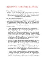
Type I
With the Type I interface, the trunk equipment generates the E signal to the PBX by grounding the E lead
(shown in Figure 3-1
). The PBX detects the E signal by sensing the increase in current through a resistive
load. Similarly, the PBX generates the M signal by sourcing a current to the trunk equipment, which detects it
through a resistive load. The numbers 7, 2, 6, and 3 are the pinouts used on an RJ-48c connector.
43
Figure 3-1. E&M Type I
Type II
E&M Type II has two additional leads over Type I: signal battery (SB) and signal ground (SG). In this method,
the E lead is paired up with the SG lead, and the M lead is paired up with the SB lead. An on-hook at the PBX
end is indicated when the E and M leads are open. Alternatively, an off-hook is indicated when the E lead is
grounded and the M lead is providing battery (see Figure 3-2
).
44
Figure 3-2. E&M Type II
Type III
E&M Type III is used mostly in older telephone company switching centers. Figure 3-3 shows the Type III
setup.
Figure 3-3. E&M Type III
45
Type IV
E&M Type IV is similar to E&M Type II; however, from the PBX side, an on-hook occurs when the E and M
leads are open, and an off-hook occurs when both leads are at ground (see Figure 3-4
).
Figure 3-4. E&M Type IV
46
Type V
Under E&M Type V, both the PBX and the switching endpoint supply battery (see Figure 3-5). At the PBX,
battery is supplied on the E lead, and at the endpoint it is supplied on the M lead. Type V is the most common
method of E&M signaling outside North America.
Figure 3-5. E&M Type V
CAS
CAS exists in many varieties that operate over various analog and digital facilities. The analog facilities are
either two- or four-wire and the digital facilities are either North American T1 or European E1. This section
discusses Bell System MF, CCITT No. 5, R1, and R2 CAS systems.
The main areas of discussion for each CAS system are supervision signaling and address signaling over
analog and digital facilities. Bell System uses in-band MF for address signaling. For supervision signaling it
uses Single Frequency for analog and a/b bits for digital trunks. CCITT No. 5 was designed for analog trunks
and uses different MF signals for supervision and address signaling. In-band tone detection is used to detect
and interpret the MF signals.
It is important to cover a few points before proceeding with a discussion of CAS systems. When a call is
placed from Exchange A toward Exchange B, Exchange A is considered the outgoing exchange and
Exchange B the incoming exchange.
One-way trunks are trunks on which only Exchange A or Exchange B can initiate a call. Exchanges A and B
can initiate a call over two-way trunks. Double seizures can occur over two-way trunks when both exchanges
try to seize the trunk at the same time, however. When this occurs, mechanisms such as timers are used to
detect and resolve such events.
Three groups of signals are present in channel-associated interexchange signaling systems:
• Supervision Signals—These signals represent events that occur on a trunk and can be specific to the
CAS variant. Signals include seizure, wink, and answer; they also are referred to as line signals.
47
• Address Signals—These signals typically represent the digits dialed or called party number and, in
some instances, other information. In this chapter, address signals are based on MF signaling and can
be system- or variant-specific.
• Tones and Announcements—These include tones such as ringing and busy tones and
announcements such as, "The number you have dialed is no longer in service."
One more concept to cover before moving forward is that of service circuits. Service circuits are used in most
exchanges to send and receive address signals and tones, as well as to play announcements. These circuits
are typically system-specific; the processor connects a path from the trunk to the appropriate service circuit
inside the switch. The pools of service circuits are temporarily used to send and receive tones or to play
announcements.
Bell System MF Signaling
This section introduces the MF signaling systems developed by Bell System in the 1950s. The Bell System is
still used today in local networks in the United States and is nearly identical to the R1 signaling system
discussed later in this chapter.
With Bell System MF signaling, which you can use on one-way or two-way trunks, supervision and address
signaling are signaled link-by-link. Supervision signaling is accomplished through a Single Frequency tone for
analog facilities and through robbed-bit signaling for digital facilities. Address information is sent through MF
tones.
Supervision Signaling
Supervision signals are continuously sent by endpoint exchanges indicating the state of the trunk. This is
known as continuous two-state signaling. States can be different at each endpoint of the trunk. MF signaling is
used to indicate on-hook and off-hook states, as listed in Table 3-2
.
Table 3-2. Supervision Signals
Direction Signal Type Transition
Forward Seizure On-hook to off-hook
Forward Clear-forward Off-hook to on-hook
Backward Answer On-hook to off-hook
Backward Clear-back Off-hook to on-hook
Backward Proceed-to-send (wink) Off-hook pulse, 120-290 ms
Supervision signals operate slightly differently for analog and digital trunks.
Analog Trunks
A Single Frequency 2600 Hz tone is used to indicate trunk state between exchanges over analog facilities.
This tone is applied in-band over the trunk and is turned off when a call is in progress or established.
Therefore, the state is on-hook or idle when the tone is present and off-hook or in use when the tone is absent.
The supervision signals for the Single Frequency method are illustrated in Figure 3-6
.
48
Figure 3-6. Forward and Backward Supervision Signals for a Call
In Figure 3-6
, assume that Switch A sends the forward signals and Switch B sends the backward signals.
Switch A sends a forward seizure or off-hook signal to Switch B on a chosen trunk. Then, Switch B sends a
backward wink or proceed-to-send to Switch A and waits for address signaling or dialed digits. After the digits
are sent and the call is answered, Switch B sends a backward answer or off-hook to Switch A, enabling an
end-to-end voice path.
In this case, the calling party hangs up first and a clear-forward is sent from Switch A to Switch B. When the
called party hangs up, a clear-back signal is sent by Switch B.
Two important aspects of this signaling method need to be discussed:
• First, Bell System MF does not have backward signaling for connections that fail during setup.
Therefore, the exchange where the call failed must connect an announcement server indicating to the
calling party that a problem occurred.
The signaling system then relies on the calling party to release or drop the call so that clear-forward
procedures can be initiated.
• Second, no release guard-type signal exists, and timers are used after trunks are released. Therefore,
after an exchange releases a trunk, it initiates a timer for approximately 1 second. After this timer
expires, the exchange assumes that the trunk was released at the other end and is available for use.
Digital Trunks
The digital trunks most commonly used today are either T1 or E1 facilities (as described in the "Physical
Layer—MTP L1" section of Chapter 4
). With digital trunks, bits are robbed from specific frames and are used
for signaling purposes. This discussion focuses on T1 digital trunks.
T1 has two types of framing formats: Super Frame (SF) and Extended Superframe (ESF). The least significant
bits are robbed from frames 6 and 12 for SF and frames 6, 12, 18, and 24 for ESF. These bits are referred to
as the Sa and Sb bits for SF, and the Sa, Sb, Sc, and Sd bits for ESF. Robbing these bits has a negligible
effect on voice quality.
The SF signaling bits—Sa and Sb—are equal to each other and provide two-state, continuous supervision
signaling. Bit values of zero are used to indicate on-hook, and bit values of 1 are used to indicate off-hook.
Address Signaling
Address signaling is used to indicate the called and calling number as well as to identify the start and end of
the address information. In the Bell System MF method, address signals are a combination of two voice-band
frequencies chosen from six different frequencies, as illustrated in Table 3-3
.
49