Teleoperation in the hybrid robot vali 2.0 for neutralization of explosives
Bạn đang xem bản rút gọn của tài liệu. Xem và tải ngay bản đầy đủ của tài liệu tại đây (492.55 KB, 13 trang )
International Journal of Mechanical Engineering and Technology (IJMET)
Volume 10, Issue 12, December 2019, pp. 354-366, Article ID: IJMET_10_12_038
Available online at />ISSN Print: 0976-6340 and ISSN Online: 0976-6359
© IAEME Publication
TELEOPERATION IN THE HYBRID ROBOT
VALI 2.0 FOR NEUTRALIZATION OF
EXPLOSIVES
Olmer García Bedoya
Department of engineering,
Universidad Jorge Tadeo Lozano, Bogota, Colombia
Vladimir Prada Jiménez
Department of engineering,
Universidad Central, Bogota, Colombia
Hoffman Ramírez
Department of mechatronics engineering,
Military Nueva Granada University, Bogota, Colombia
ABSTRACT
Mobile robots have recently been used in different environments in order to
safeguard the life and integrity of people in high-risk situations. Proof of this is the
military robots that are used to Improvised Explosive Devices. These kinds of
platforms are generally teleoperated through a control station or electronic devices
such as gamepad. The primary function of these robots is to move to the site and
manipulate elements which present risk, while well as transmit images with cameras.
Behind all the mechanical engineering that supports the structure and gives the robot
the ability to interact with its surroundings, a sophisticated electronic system that
operates the different robot systems (caterpillars, cameras, manipulator arm) is
hidden. This document describes the embedded electronics and programming system
implemented in the robot VALI 2.0(Vehiculo Antiexplosivo Ligero in Spanish) to
neutralize explosive devices, showing from its general architecture to the
implementation and programming of the embedded computer at the robot and the
portable equipment used to mount the control station. Finally, the electronic and
communications system tests carried out together with the mechanical tests of the
robot in different environments are shown.
Keywords: Teleoperation, hybrid robot, embedded systems, neutralization of
explosives.
Cite this Article: Olmer García Bedoya, Vladimir Prada Jiménez, Hoffman Ramírez,
Teleoperation in the Hybrid Robot Vali 2.0 for Neutralization of Explosives.
International Journal of Mechanical Engineering and Technology 10(12), 2019, pp.
354-366.
/>
/>
354
Teleoperation in the Hybrid Robot Vali 2.0 for Neutralization of Explosives
1. INTRODUCTION
The neutralization of Improvised Explosive Artifacts (IEA) is a high-risk task that involves
the manipulation of explosives directly prepared in order to cause injury to people [1, 2, 3, 4].
This work is carried out in multiple ways, from the humanitarian demining [5, 6, 7], the
neutralization of explosive devices directly by special forces personnel, to the use of
technological tools such as hybrid platforms [8, 9, 10, 11, 12] equipped with accessories for
the neutralization of explosives[13,14,15].
In Colombia, the neutralization of explosives is carried out in most cases through human
operators directly. In this case are the anti-explosive technicians of the different forces
(police, army, navy) and which are directly involved in the manipulation of explosive devices
when such devices are suspected.
When the manipulation of an IEA is done directly by a person, it uses an armored uniform
[16, 17, 18], which gives it a certain degree of protection against the explosive wave, and
especially against the shrapnel that can be fired at the moment of detonation [19]. However,
uniform protection is not adequate within specific ranges of distance, which depends on the
location of the explosive device, the amount and explosive, and the disposition or enclosure of
the explosive inside the device.
The neutralization of explosive devices in Colombia is mostly carried out manually due to
the low number of robotic platforms that allow this work to be carried out, the malfunctions
they present due to incidents, and the difficulty presented by logistics and handling of some of
these robotic platforms.
Some of the most used commercial platforms for the neutralization of explosives
worldwide are available in the anti-explosive bodies of the Colombian armed forces. One of
them is the Talon robot [8, 20], manufactured by the company Qinetiq; This is a robot that is
widely used by military forces around the world. The Safariland Group, under the Med-Eng
brand, is the manufacturer of the Avenger Robot robots, the Digital Vanguard ROV, and the
Defender ROV [9]. The Digital Vanguard ROV robot can carry a disruptive cannon and is
one of the robots used by the anti-explosive personnel of the Colombian national police for
neutralization work. The FLIR Packbot robot [10, 21], is a compact robot with a caterpillar
system and an anthropomorphic arm, just like the other platforms already mentioned.
Another development, Rescuer [22], is a robot specially designed for intervention work
under chemical, biological, radiological, and nuclear risk environments. It consists of a
mobile platform that works with wheels or tracks and has a manipulator arm of five degrees
of freedom (5-GDL), which can be attached or removed, depending on the mission. The
communications system can be by fiber-optic (up to 100m), 3G wireless (up to 1km), or
wireless by radio signals (up to 50 km in line of sight).
In the academic field there are some developments in this subject. The work published by
B. Wei et al. [23], shows a robot for disposal of explosives, which has a processor embedded
in the computer to transmit the images of the 5 cameras of the robot, as well as to operate the
robot by means of the different buttons arranged for that purpose in the control Panel. This
robot has a 500m wireless range and a 150m wired backup system.
A robot with a similar architecture in its operating system is developed by M. Fracchia et
al. [24] Use a portable computer as a remote-control station, and through a gamepad allows
the operator to operate the robot. Using WiFi communication, it connects to the robot, which
has an embedded computer on board, responsible for operating the motor system; the cameras
transmit directly to the control station without going through the embedded system.
The VALI 2.0 robot [25] is the second prototype of the line of research on teleoperated
military vehicles worked jointly between the New Granada Military University and the
/>
355
Olmer García Bedoya, Vladimir Prada Jiménez, Hoffman Ramírez
Colombian Military Industry. The development arose from the need to have a platform
locally, which allow lower manufacturing and maintenance costs to facilitate the acquisition
of this kind of platform by the different anti-explosive bodies of Colombia. It is a mobile
platform using tracks, which have a 5-GDL anthropomorphic manipulator arm. It has a
multifunction clamp as an end effector, and they can mate with different accessories, such as a
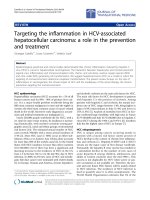
disruptive barrel. Its construction can be seen in Figure 1.
A person teleoperates the robot through a gamepad, which is connected to a laptop or
control station, which finally communicates with the robot via optical fiber or wireless
medium. The images of the three cameras of the robot are displayed on the laptop, and access
to the handling of other robot systems such as lights, lasers, and cannon firing is available.
Figure 1. VALI 2.0 Robot
2. ARQUITECTURA DEL HARDWARE
This section describes the robot's hardware components such as actuation systems,
communications, vision, data processing centers and energy sources.
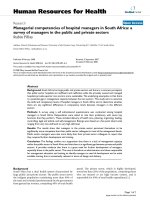
The hardware architecture of the VALI 2.0 robot can be seen in Figure 2. This architecture
with respect to that of VALI 1.0 [26], in its concept is very similar, however, the devices that
compose it have changed significantly with the purpose to reduce energy consumption, reduce
costs and increase the processing and communications capacity, as well as to facilitate the
handling of exterior housings. This architecture with respect to hardware can be divided into
five functional blocks described below.
2.1. Robot Actuation System
This system requires an iteration phase to select the appropriate actuators that support the
loads and speeds required both in the locomotion system (tracks) and in the robotic arm
system.
The robotic arm is composed of five degrees of freedom: two on the shoulder, one on the
elbow, and two on the wrist, which is controlled by servomotors. The first iteration was made
with the static arm to determine nominal torques and dimension the required engines and
transmission systems. Following this, with designed geometries and inertia, the inverse
dynamics analysis of the arm was performed through the SolidWorks Motion tool. Critical
scenarios were simulated for each degree of freedom, in order to find the instantaneous
torques, which later allowed to estimate the nominal and peak torques of the actuators, as well
as required energy consumption.
/>
356
Teleoperation in the Hybrid Robot Vali 2.0 for Neutralization of Explosives
With these data, we proceeded to select some servomotors that integrate the electronics
and provide their data network called Combitronics. This network, although quite reliable and
that allows to connect the motors in a chain, has all servomotors received a transmission
speed of only 115200 bps. To increase the response time was implemented a protocol through
the firmware of the motors obtaining minimize the frames and take advantage of any
information sent by the protocol.
In addition to the relative current and encoder sensors embedded in the servomotors,
absolute angular position sensors were adapted at the outlet after the reducer. In the case of
motors that work in pairs (shoulder and wrist), it is necessary to ensure synchrony between
the encoders, so each couple of motors where configured in cam mode. This approach lets that
changing the direction of the cam, change the degree of joint freedom from the z-axis to the xaxis.
In the case of caterpillars, the two-dimensional models proposed in [27], [28] and [29]
were analyzed. These models were simulated for the characteristics of the vehicle in static
conditions and contrasted with the experimental results made VALI I. However, the dynamic
simulation scenario was very simplified concerning the actual operating conditions, which
required increasing the margins of security in the design of this system. For handling the track
system, the motors communicate through an independent network of the arm motors to
increase the speed and reliability of the robot.
2.2. System Shipped under Linux
The vehicle processing unit used in VALI 1.0 works under ARM architecture, this prevented
the use of Linux tools [26]. Therefore, different options were analyzed in X86 architecture.
The solution was to use the embedded fit-pc2i system interconnected to a microcontroller
through a USB port, explained in the next section.
The embedded system has a solid-state storage unit. The embedded works as a router with
the purpose of generating energy efficiency and allows a range of possibility in wireless
power and security settings, to configure by software an internal network of the vehicle and
an external one for the output of the required information to the station of control or other
devices. Additionally, the on-board system can receive the connection of the servomotor data
networks and the communication with the on-board microprocessed system and an infrared
connection to a gamepad for robot manipulation without the need for a control station.
2.3. Electronic System with Microcontroller
This card has a Microchip microcontroller as a processing center, which is connected to a
series of peripherals that the robot has such as: an inertial system, a camera lighting system,
manipulation of the manipulator or gripper motor, as well as a series of signals specially
designed to activate the disruptor cannon. The block diagram is presented in Figure 3.
According to these peripherals the following ports were designed:
2 - digital outputs per 12V relay
1 - digital output per 24V relay
2 - 24V differential digital outputs
1 - temperature sensor
2 - analog inputs programmed to measure battery voltage and current consumption
1 - common 12V / 3A emitter output (for lighting)
Programmable port of 8 DI/DO at 5V
/>
357
Olmer García Bedoya, Vladimir Prada Jiménez, Hoffman Ramírez
5 - AI / DI / DO 5V programmable port
1 - RS232 port and an i2c port to connect components such as the inertial control panel
designed to carry out trajectory control.
As a power supply system, two 10-cell lithium-ion batteries were used, which have 12V
and 24V DC-DC sources connected for the different needs of the system elements.
Figure 2. VALI 2.0 hardware architecture
Figure 3. Block diagram of the electronic system with microcontroller.
2.4. Vision System
For the vision system, three options were analyzed as described in Table 1. The analog
cameras were discarded because two transmission means would be needed between the
control station and the vehicle and, in addition, if processing was required on the robot, it
would require double hardware.
/>
358
Teleoperation in the Hybrid Robot Vali 2.0 for Neutralization of Explosives
The IP cameras used in VALI 1.0 worked very well, however, their cost and energy
consumption are high, therefore, a hybrid solution was chosen. This solution uses two
integrated cameras (webcam) for the on-board system in order to reduce energy consumption,
decrease the amount of cables and decrease the size. The third camera was IP, because the
required optical zoom and camera motion actuators require further development to adapt to
USB cameras. The above allowed to eliminate the internal router of the vehicle, since the onboard system has two Ethernet ports, the first one was configured as a local network and this
camera is connected.
Table 1. Comparison of technologies for vision
Type
IP cameras
Analog cameras
Embedded Cameras
(webcam)
Advantage
Disadvantages
Wireless
Integration with the control
station
cost
Limited to wireless or Ethernet
transmission
Commercial
Lenses
Costs
Space
Robot Processing
Scanning at the control station
Transmission system
Integration
Lenses
Information transmission
2.5. Remote Control Station
According to the results obtained from phase 1, the control station had a low memory and
processing use, therefore, evaluating the current technology an Intel iCore 3 or equivalent was
considered sufficient to handle the streaming of the three cameras and to be a client of the API
(Application Programming Interface) for connection to the robot. This computer for its field
characteristics was selected with IP65 protection and embedded in a box with a gamepad
control for robot manipulation.
The communication system between the control station and the laptop is one of the points
that requires further testing, given the uncertainty of the indoor Wi-Fi network. For this, given
the simplification of only having a communications path (the ethernet port of the fit pc), it
allowed to open the horizon of access point devices, which have better features than
commercial routers in terms of capabilities and functionality over wireless communication.
After evaluating different options, the solution proposed in communications is that between
the robot there will be a 2HP bullet to the ethernet port of the fit-pc and to a Trendnet 8dbi
antenna.
The control station is connected by means of the network card of the laptop and according
to the coverage requirement there will be two options: the first one is the high-power wireless
adapter; and the second a 2HP bullet. Both were configured in a proprietary protocol to
improve reception over long distances.
3. SOFTWARE ON THE ROBOT EMBEDDED COMPUTER
The software architecture of the robot computer is running on Linux UBUNTU and, in
addition, the programs shown in Figure 3 are running. The DSERIAL, DPIC, DCDM,
DJoystick, Fmon and Fcdm programs are programs specifically made in the draft. The MjpegStreamer program in charge of webcam video was selected considering that the processing
consumption required within the system. Since this webcam server requests the MJPEG frame
directly from the USB camera, this makes the processing in the system minimal. Programs
/>
359
Olmer García Bedoya, Vladimir Prada Jiménez, Hoffman Ramírez
such as ffmpeg were also evaluated for video streaming, however, when two webcams of the
same brand are used, this creates conflicts.
Mjpeg-streamer
M3
Mjpeg-streamer
F1
Apache
DCDM
DSERIAL
M2
M4
FCGI
Djoystick
M1
Fmon Fcdm
DPIC
Boot Linux Ubuntu 10.04LTS
Shutdown Linux Ubuntu
Figure 4. Software architecture in the robot's embedded system.
The software developed uses a memory system independent of the memories shared with
the web services, in order to provide security in accessing the hardware through the DCDM
program. This is responsible for processing all information from the control of the remote
station or joystick to improve security.
The DPIC and DSERIAL programs are responsible for communicating with the
microcontroller and the motors respectively, these are separated from the DCDM program,
with two purposes: the first to allow the three programs to be asynchronous so that the
hardware tasks do not block the processing of the Information and the second is that since
they are hardware tasks that require a large load of interruptions, they do not generate
problems in the cycle times of the movement control (DCDM). Table 2 has an explanatory list
of each of the robot's services.
Table 2. Average cycle time of the different scripts.
Script
DSERIAL
Cycle Time
50Hz
DPIC
100Hz to 500Hz
DCDM
100Hz
DJoystick
100Hz
Fmon
Fcdm
-----
Description
In charge of communicating with the servomotors, two
are executed independently, one of high priority to
control the robot tracks and another of lower priority
for the robot arm.
Communication with the microcontroller embedded
system using the USB protocol in bulk mode.
Script responsible for carrying out the robot control
logic. It is responsible for merging the data in order to
make decisions such as limiting speeds or preventing
possible interference.
Although the joystick events are asynchronous, a cycle
time has been programmed to decrease the load of
calculations in DCDM.
Fmon and Fcdm, are the API for the robot monitoring
and control respectively. Both are asynchronous, so
they function as a server to the control station requests.
One of the main issues with VALI's 1.0 architecture was, in case of an error there was not
much information about it [26]. In this prototype, each script must inform the source of an
error. For example, in table 3 the error dictionary for the DPIC script is presented.
/>
360
Teleoperation in the Hybrid Robot Vali 2.0 for Neutralization of Explosives
Table 3. Error dictionary for the Microcontroller.
Group
0
No error
-1X
-10
-11
-12
-13
Error initializing the micro
Device not found function device_init
Failed to open device function run usb_open
Failed to request the device function usb_claim_interface
-2X
-20
-21
-22
-23
-30
-31
-32
-33
No micro data was read
Error reading micro data
Error sending micro data
Error converting micro analog data
Error closing the micro
Failed to release device usb_release_interface function
Failed to close device function run usb_close
Device not found while closing the micro
-3X
Another main issue with VALI's 1.0 architecture was the synchronization of the
commands sent by the control station, which caused serious problems in adverse
communications conditions. In the proposed architecture, the DCDM script has a watch dog
to put the robot in a loss connection condition. In other words, the service client through a
timeout variable will define the maximum time in which a command must reach the
computer, in case this does not occur, it will stop the actions and leave the robot in a safe
state.
To solve the problem of multiple control sources, a FIFO list is normally used to receive
the commands, however, given the communication problems that may occur with the control
station and the fact the motors are controlled by speed, as the user is the position controller, a
traffic light securely accessed variable is created using the blocksem and unblocksem
functions created in the common services library. Therefore, only if a control station timeout
command exists, commands from the internal joystick will be received. In this way the remote
commands remain a priority, since the cycle time of the control station is usually between
5Hz and 15Hz (limited by the Wifi network) which is much less than the cycle time of the
joystick operating at 100Hz.
On the communication API via http protocol with the control station, an Apache server
where web pages for configuration and monitoring of the robot were developed is used. In
this case, the Fmon and Fcdm scripts were implemented with the fastcgi protocol [30], with
the purpose of being executed in a persistent manner, reducing the time and use of the
processor required by a program to be created. Tests conducted on a wired network showed
that the reaction times to a request decreased from an average of 10ms to periods between
1ms and 2ms with a decrease in processor usage.
On the security issue, in addition to being able to configure users through apache’s
configuration, all the security from netfilters was configured on the embedded computer using
iptables [31].
To facilitate the configuration process Webmin is installed ( />Webmin is a web server that through a web interface allows to configure and monitor all
Linux functions. This program is turned off by default and is configured to work only on the
robot's internal network.
/>
361
Olmer García Bedoya, Vladimir Prada Jiménez, Hoffman Ramírez
4. CONTROL STATION PROGRAMMING
The control station program was created in C # under the .NET Framework 4.0, mainly due to
the ease of handling the COM component of the IP camera and the Windows functions to
block any other type of use of the equipment. The classes’ scheme is presented in Figure 5.
One of the great improvements is that the connections to the cameras and to the command and
monitoring servers are being made asynchronous, which allows the robot to run smoothly
even if the cameras are disconnected, also eliminates operating latencies in case any system
component failed.
Figure 5. Classes diagram of the control station application.
The control station script has the interface shown in Figure 6. The program allows to
visualize the status and variables of the robot components, given the error dictionary
described in the previous section. It is noteworthy that according to the type of user accessing
the equipment, the interface will allow to configure both the control station parameters, as
well as the robot parameters, this through the web configuration and configuration tabs to
access the servers of the IP camera or the robot.
Figure 6. Control station interface.
5. TESTS AND RESULTS
The VALI 2.0 robot had different field tests aiming to verify:
The ability to move.
The performance of the manipulator arm.
The wireless signal range and image quality at the control station.
/>
362
Teleoperation in the Hybrid Robot Vali 2.0 for Neutralization of Explosives
To assess the robot's ability to move and the tracks system operation, tests were performed
by climbing stairs on a surface inclined by 40°, see Figure 7 (left). In the tests carried out, it
was observed that the robot was able to climb the slope from a resting position and that the
grip between the tracks and the surface was adequate. Likewise, the performance of the tracks
system was evaluated, observing that there was no slippage between the transmission system
and the belt, but there was derailment of the belt due to a mismatch of the tensioning system.
Another test to evaluate movement is the load with dead weight test, Figure 7 (right). In
this test it is observed that the robot can drag a 45kg load on a rough surface and a vehicle on
a flat terrain.
Figure 7. Locomotion test
To evaluate the arm´s performance two tests were carried out, the first evaluates the
manipulation of objects in a critical condition (arm fully stretched in a horizontal position)
and the second evaluates the arm stiffness before firing with the disruptive barrel, Figure 8
(left). In the first test it was observed that the arm was able to lift a 5kg load.
In the second test, Figure 8 (right), it was observed that the structure supports the effects
produced (explosion, recoil, etc.) by shots made with copper ammunition.
To assess the range of the WiFi signal, signal strength measurements were made as the
robot moved away from the control station. The measurements were made with a spectrum
meter, reporting a power of -70dBm at 40m with obstacles and 120m in line of sight. It is
important to mention that this type of signal is considered adequate and that it can present
problems in the presence of rain and wind. Similarly, it was verified that the image quality of
the cameras will not be affected by latency problems or loss of communication.
Figure 8. Manipulator performance test.
6. CONCLUSION
With the proposed robot hardware architecture, a simplification of components was sought in
order to eliminate errors and reduce energy consumption compared to the previous version.
This simplification required a redesign of the communication protocols used between the
/>
363
Olmer García Bedoya, Vladimir Prada Jiménez, Hoffman Ramírez
devices. To achieve this, it was necessary to develop a specific firmware on the servomotors
and the microcontroller system, which allowed to clearly define the possible operation failures
of the systems.
The software architecture was designed looking for asynchrony between the processes, for
which different schemes were used to share information between them based on Linux IPC.
This allowed to include security strategies, ease of maintenance and debugging of the
different processes in the design.
Different alternatives were explored in order to maximize distances and minimize
communication latency in the communication with the control station. This accompanied by a
software design in the control station based on asynchronous events, allowed to significantly
improve the handling experience of the robot with respect to VALI 1.0 [26].
Future work includes the incorporation of autonomy functions of the robot through
artificial vision and the integration of specific sensors for the task.
ACKNOWLEDGMENTS
The authors would like to thank the Nueva Granada Military University for the financial
support on the ING 586 project development “Development of a vehicle for transport of
disruptive cannon phase 2”. In the same way, these thanks are extended to the Colombian
Military Industry - Indumil - for their contributions for the benefit of the development of the
project.
REFERENCES
[1]
DescontaMina Colombia,» Centro Nacional Contra AEI y Minas, 2019. [En línea].
Available:
/>y%20AEI.pdf.
[2]
Manual de seguridad sobre Minas terrestres, Restos de Explosivos de Guerra y AEI,
Naciones Unidas, 2015. [En línea]. Available:
/>
[3]
Artefactos Explosivos, Universidad Nacional Autónoma de México, 2011. [En línea].
Available: />vos.pdf.
[4]
M. Illera Lobo y E. Contreras Silva, Población infanti colombiana, víctima de artefactos
explosivos, Justicia, pp. 224-238, 2018.
[5]
Desminar para iluminar, Revista Semana, 26 11 2018. [En línea]. Available:
/>
[6]
J. A. Orozco Sánchez, Informe. Programa de desminado de emergencia, Relaciones
Estudios de Historia y Sociedad, pp. 115-131, 2018.
[7]
D. P. Arias y J. M. Ospina Perdomo, Desminado humanitario en los escenarios
coyunturales del posconflicto colombiano: una mirada jurídico-política, Desafios, 2019.
[8]
TALON, Medium-Sized Tactical Robot,» QinetiQ North America, 2019. [En línea].
Available: />
/>
364
Teleoperation in the Hybrid Robot Vali 2.0 for Neutralization of Explosives
[9]
Digital Vanguard ROV, Med-Eng, 2019. [En línea]. Available: />
[10]
FLIR
PackBot,
FLIR,
2019.
/>
[11]
S. Odedra, S. Prior y M. Karamanoglu, Investigating the Mobility of Unmanned Ground
Vehicles, Proceedings of the International Conference on Manufacturing and Engineering
Systems, 2009.
[12]
L. Xuewen, M. Cai, L. Jianhong y W. Tianmiao, Research on Simulation and Training
System for EOD Robots, 4th IEEE International Conference on Industrial Informatics, pp.
810-814, 2006.
[13]
S. C. Alford, Device for the disruption of explosive objects. Estados Unidos Patente US
6,584,908 B2, 01 Julio 2003.
[14]
M. Bowman, M. Summer y P. Bosscher, Schock absorbing disruptor mounting system.
Estados Unidos Patente US 2018/0156562 A1, 07 Junio 2018.
[15]
I. Vabnick, A. Ellis y J. Rithenberger, Low impact threat rupture device for explosive
ordnance disruptor». Estados Unidos Patente US 10,066,916 B1, 04 Septiembre 2018.
[16]
Productos EOD/IEDD, Garant Protects, 2019. [En línea]. Available: />
[17]
El revolucionario traje blindado a prueba de bombas y llamas, La Gaceta, 1 Noviembre
2017. [En línea]. Available: />
[18]
R. Beland, M. Slobozianu y L. Scafita, «Bomb Disposal Suit». Estados Unidos Patente US
D787,131 S, 16 Mayo 2017.
[19]
J. Yenesa, R. Castedo, A. Santos y J. Simónca, Experimentación, simulación y análisis de
artefactos improvisados - proyectiles formados por explosión, Revista Internacional de
Métodos Numéricos para Cálculo y Diseño en Ingeniería, vol. 32, nº 1, pp. 48-57, 2016.
[20]
P. Wells y D. Deguire, TALON : a universal unmanned ground vehicle platform, enabling
the mission to be the focus, Unmanned Ground Vehicle Technology VII, 27 Mayo 2005.
[21]
B. Yamauchi, PackBot: A Versatile Platform for Military Robotics, Unmanned Ground
Vehicle Technology VI, 2 Septiembre 2004.
[22]
R. Guzmán, R. Navarro, J. Ferre y M. & Moreno, «RESCUER: Development of a
Modular Chemical, Biological, Radiological, and Nuclear Robot for Intervention,
Sampling, and Situation Awareness,» Journal of Field Robotics, pp. 931-945, 2015.
[23]
B. Wei, J. Gao, J. Zhu y K. Li, «Design of a Large Explosive Ordnance Disposal Robot,»
Second International Conference on Intelligent Computation Technology and Automation,
pp. 403-406, 2009.
[24]
M. Fracchia, M. Benson, C. Kennedy, J. Convery y A. Poultney, «Low-cost explosive
ordnance disposal robot for deployment in Southeast Asia,» IEEE Canada International
Humanitarian Technology Conference, pp. 1-4, 2015.
/>
365
[En
línea].
Available:
Olmer García Bedoya, Vladimir Prada Jiménez, Hoffman Ramírez
[25]
H. Ramirez Guio, O. Garcia Bedoya y O. Avilés Sánchez, VALI: Desarrollo y Evolución
de un Robot Para Neutralizar Explosivos, RISTI - Revista Iberica de Sistemas y
Tecnologias de Información, pp. 355-369, 2019.
[26]
O. Garcia, L. Solaque, O. Aviles y P. Nino, Hardware and software architecture of a
mobile robot with anthropomorphic arm, de 2010 IEEE ANDESCON, Bogota, 2010.
[27]
J. Y. Wong., Theory of Ground VehIcles., third edition ed., NY: John Wiley, 1993.
[28]
A. T. Le, D. C. Rye y H. F. Durrant-Whyte, Estimation of track-soil interactions for
autonomous, de Proceedings of International Conference on Robotics and Automation,
Albuquerque, 1997.
[29]
V. P. a. R. H. M. Ahmadi, «Path Tracking Control of Tracked Vehicles,» de Proceedings
2000 ICRA. Millennium Conference. IEEE International Conference on Robotics and
Automation., San francisco, 2000.
[30]
P. SIMONS y R. BABEL, Fast CGI the forgotten treasure,» de ApacheCon Europe, 2001.
[31]
G. N. PURDY, Linux iptables Pocket Reference: Firewalls, NAT & Accounting, New
york: O'Reilly Media, Inc., 2004.
/>
366