The safety critical systems handbook a straightforward guide to functional safety IEC 61508 (2010 edition), IEC 61511 (2015 edition) and related guidance ( TQL )
Bạn đang xem bản rút gọn của tài liệu. Xem và tải ngay bản đầy đủ của tài liệu tại đây (5.8 MB, 332 trang )
The Safety Critical Systems
Handbook
This page intentionally left blank
The Safety Critical Systems
Handbook
A Straightforward Guide To Functional Safety: IEC 61508
(2010 Edition), IEC 61511 (2016 Edition) & Related
Guidance
Including Machinery and other industrial sectors
FOURTH EDITION
Dr David J Smith
Kenneth GL Simpson
AMSTERDAM • BOSTON • HEIDELBERG • LONDON • NEW YORK • OXFORD
PARIS • SAN DIEGO • SAN FRANCISCO • SINGAPORE • SYDNEY • TOKYO
Butterworth-Heinemann is an imprint of Elsevier
Butterworth-Heinemann is an imprint of Elsevier
The Boulevard, Langford Lane, Kidlington, Oxford OX5 1GB, United Kingdom
50 Hampshire Street, 5th Floor, Cambridge, MA 02139, United States
Copyright Ó 2016 Dr David J Smith and Kenneth G L Simpson. Published by Elsevier Ltd. All rights reserved.
No part of this publication may be reproduced or transmitted in any form or by any means, electronic or mechanical,
including photocopying, recording, or any information storage and retrieval system, without permission in writing
from the publisher. Details on how to seek permission, further information about the Publisher’s permissions
policies and our arrangements with organizations such as the Copyright Clearance Center and the Copyright
Licensing Agency, can be found at our website: www.elsevier.com/permissions.
This book and the individual contributions contained in it are protected under copyright by the Publisher (other than
as may be noted herein).
Notices
Knowledge and best practice in this field are constantly changing. As new research and experience broaden our
understanding, changes in research methods, professional practices, or medical treatment may become necessary.
Practitioners and researchers must always rely on their own experience and knowledge in evaluating and using any
information, methods, compounds, or experiments described herein. In using such information or methods they
should be mindful of their own safety and the safety of others, including parties for whom they have a professional
responsibility.
To the fullest extent of the law, neither the Publisher nor the authors, contributors, or editors, assume any liability for
any injury and/or damage to persons or property as a matter of products liability, negligence or otherwise, or from
any use or operation of any methods, products, instructions, or ideas contained in the material herein.
Library of Congress Cataloging-in-Publication Data
A catalog record for this book is available from the Library of Congress
British Library Cataloguing-in-Publication Data
A catalogue record for this book is available from the British Library
ISBN: 978-0-12-805121-4
For information on all Butterworth-Heinemann publications
visit our website at />
Publisher: Joe Hayton
Acquisition Editor: Fiona Geraghty
Editorial Project Manager: Maria Convey
Production Project Manager: Jason Mitchell
Designer: Matthew Limbert
Typeset by TNQ Books and Journals
Contents
A Quick Overview ............................................................................................ xv
The 2010 Version of IEC 61508...................................................................... xvii
The 2016 Version of IEC 61511....................................................................... xix
Acknowledgments ............................................................................................ xxi
PART A: THE CONCEPT OF SAFETY INTEGRITY ........................................... 1
Chapter 1 The Meaning and Context of Safety Integrity Targets ........................... 3
1.1 Risk and the Need for Safety Targets.......................................................................... 3
1.2 Quantitative and Qualitative Safety Target ................................................................. 6
1.3 The Life-Cycle Approach ............................................................................................ 9
Section 7.1 of Part 1 .....................................................................................................9
1.4 Steps in the Assessment Process ............................................................................... 13
Step 1. Establish Functional Safety Capability (i.e., Management)..........................13
Step 2. Establish a Risk Target ..................................................................................13
Step 3. Identify the Safety Related Function(s).........................................................13
Step 4. Establish SILs for the Safety-Related Elements ...........................................13
Step 5. Quantitative Assessment of the Safety-Related System ...............................14
Step 6. Qualitative Assessment Against the Target SILs ..........................................14
Step 7. Establish ALARP ...........................................................................................14
1.5 Costs ........................................................................................................................... 15
1.5.1 Costs of Applying the Standard ...................................................................... 15
1.5.2 Savings from Implementing the Standard....................................................... 15
1.5.3 Penalty Costs from Not Implementing the Standard ...................................... 15
1.6 The Seven Parts of IEC 61508 .................................................................................. 16
1.7 HAZOP (Hazard and Operability Study) .................................................................. 19
1.7.1 Objectives of a HAZOP................................................................................... 20
1.7.2 HAZOP Study Team........................................................................................ 20
1.7.3 Typical Information Used in the HAZOP....................................................... 21
1.7.4 Typical HAZOP Worksheet Headings ............................................................ 22
1.7.5 Risk Ranking ................................................................................................... 23
1.7.6 Quantifying Risk.............................................................................................. 23
v
vi Contents
Chapter 2 Meeting IEC 61508 Part 1.............................................................. 25
2.1 Establishing Integrity Targets .................................................................................... 25
2.1.1 The Quantitative Approach ............................................................................. 25
2.1.2 Layer of Protection Analysis........................................................................... 34
2.1.3 The Risk Graph Approach............................................................................... 36
2.1.4 Safety Functions .............................................................................................. 38
2.1.5 “Not Safety-Related” ....................................................................................... 39
2.1.6 SIL 4 ................................................................................................................ 39
2.1.7 Environment and Loss of Production.............................................................. 40
2.1.8 Malevolence and Misuse ................................................................................. 40
2.2 “As Low as Reasonably Practicable” ........................................................................ 40
2.3 Functional Safety Management and Competence..................................................... 44
2.3.1 Functional Safety Capability Assessment ....................................................... 44
2.3.2 Competency ..................................................................................................... 44
2.3.3 Independence of the Assessment..................................................................... 48
2.3.4 Hierarchy of Documents.................................................................................. 48
2.3.5 Conformance Demonstration Template........................................................... 49
IEC 61508 Part 1......................................................................................................... 49
2.4 Societal Risk .............................................................................................................. 50
2.4.1 Assess the Number of Potential Fatalities ...................................................... 50
2.4.2 It Is Now Necessary to Address the Maximum Tolerable Risk ..................... 50
2.4.3 The Propagation to Fatality ............................................................................. 51
2.4.4 Scenarios with Both Societal and Individual Implications............................. 52
2.5 Example Involving Both Individual and Societal Risk............................................. 52
2.5.1 Individual Risk Argument ............................................................................... 52
2.5.2 Societal Risk Argument................................................................................... 53
2.5.3 Conclusion ....................................................................................................... 55
Chapter 3 Meeting IEC 61508 Part 2.............................................................. 57
3.1 Organizing and Managing the Life Cycle................................................................. 57
Sections 7.1 of the Standard: Table ‘1’......................................................................57
3.2 Requirements Involving the Specification................................................................. 59
Section 7.2 of the Standard: Table B1 (avoidance) ...................................................59
3.3 Requirements for Design and Development.............................................................. 60
Section 7.4 of the Standard: Table B2 (avoidance) ...................................................60
3.3.1 Features of the Design..................................................................................... 60
Sections 7.4.1e7.4.11 excluding 7.4.4 and 7.4.5 ......................................................60
3.3.2 Architectures (i.e., SFF) .................................................................................. 63
Section 7.4.4 Tables ‘2’ and ‘3’ .................................................................................63
3.3.3 Random Hardware Failures ............................................................................. 66
Section 7.4.5 ...............................................................................................................66
3.4 Integration and Test (Referred to as Verification)..................................................... 66
Section 7.5 and 7.9 of the Standard Table B3 (avoidance) .......................................66
Contents vii
3.5 Operations and Maintenance ..................................................................................... 67
Section 7.6 Table B4 (avoidance) ..............................................................................67
3.6 Validation (Meaning Overall Acceptance Test and the Close Out of Actions) ....... 67
Section 7.3 and 7.7: Table B5 ....................................................................................67
3.7 Safety Manuals........................................................................................................... 68
Section 7.4.9.3e7 and App D ....................................................................................68
3.8 Modifications.............................................................................................................. 68
Section 7.8 ..................................................................................................................68
3.9 Acquired Subsystems ................................................................................................. 68
3.10 “Proven in Use” (Referred to as Route 2s in the Standard)...................................... 69
3.11 ASICs and CPU Chips............................................................................................... 70
(a) Digital ASICs and User Programmable ICs.........................................................70
Section 7.4.6.7 and Annex F of the Standard ............................................................70
(b) Digital ICs with On-Chip Redundancy (up to SIL 3) .........................................70
Annex E of the Standard ............................................................................................70
3.12 Conformance Demonstration Template ..................................................................... 71
IEC 61508 Part 2 .......................................................................................................... 71
Chapter 4 Meeting IEC 61508 Part 3.............................................................. 79
4.1 Organizing and Managing the Software Engineering............................................... 79
4.1.1 Section 7.1 and Annex G of the Standard Table “1” ..................................... 79
4.2 Requirements Involving the Specification................................................................. 83
4.2.1 Section 7.2 of the Standard: Table A1 ............................................................ 83
4.3 Requirements for Design and Development.............................................................. 83
4.3.1 Features of the Design and Architecture......................................................... 83
4.3.2 Detailed Design and Coding ........................................................................... 84
4.3.3 Programming Language and Support Tools.................................................... 84
4.4 Integration and Test (Referred to as Verification)..................................................... 85
4.4.1 Software Module Testing and Integration....................................................... 85
4.4.2 Overall Integration Testing.............................................................................. 85
4.5 Validation (Meaning Overall Acceptance Test and Close Out of Actions).............. 86
Paragraphs 7.3, 7.7, 7.9, Table A7 .............................................................................86
4.6 Safety Manuals........................................................................................................... 86
(Annex D) ...................................................................................................................86
4.7 Modifications.............................................................................................................. 87
Paragraph 7.6, 7.8, Table A8 and B9.........................................................................87
4.8 Alternative Techniques and Procedures..................................................................... 87
4.9 Data-Driven Systems ................................................................................................. 88
4.9.1 Limited Variability Configuration, Limited Application Configurability ...... 88
4.9.2 Limited Variability Configuration, Full Application Configurability............. 88
4.9.3 Limited Variability Programming, Limited Application Configurability....... 89
4.9.4 Limited Variability Programming, Full Application Configurability............. 89
viii Contents
4.10 Some Technical Comments ....................................................................................... 89
4.10.1 Static Analysis............................................................................................... 89
4.10.2 Use of “Formal” Methods............................................................................. 90
4.10.3 PLCs (Programmable Logic Controllers) and their Languages................... 90
4.10.4 Software Reuse.............................................................................................. 91
4.10.5 Software Metrics ........................................................................................... 92
4.11 Conformance Demonstration Template ..................................................................... 92
IEC 61508 Part 3........................................................................................................... 92
Chapter 5 Reliability Modeling Techniques ...................................................... 101
5.1 Failure Rate and Unavailability ............................................................................... 101
5.2 Creating a Reliability Model ................................................................................... 101
5.2.1 Block Diagram Analysis................................................................................ 102
5.2.2 Common Cause Failure (CCF)...................................................................... 110
5.2.3 Fault Tree Analysis........................................................................................ 115
5.3 Taking Account of Auto Test .................................................................................. 116
5.4 Human Factors ......................................................................................................... 119
5.4.1 Addressing Human Factors ........................................................................... 119
5.4.2 Human Error Rates ........................................................................................ 121
5.4.3 A Rigorous Approach.................................................................................... 123
Chapter 6 Failure Rate and Mode Data.......................................................... 125
6.1 Data Accuracy.......................................................................................................... 125
6.2 Sources of Data ........................................................................................................ 127
6.2.1 Electronic Failure Rates ................................................................................ 128
6.2.2 Other General Data Collections .................................................................... 128
6.2.3 Some Older Sources ...................................................................................... 129
6.2.4 Manufacturer’s Data ...................................................................................... 130
6.2.5 Anecdotal Data .............................................................................................. 130
6.3 Data Ranges and Confidence Levels ....................................................................... 130
6.4 Conclusions .............................................................................................................. 132
Chapter 7 Demonstrating and Certifying Conformance ..................................... 135
7.1 Demonstrating Conformance ................................................................................... 135
7.2 The Current Framework for Certification................................................................ 135
7.3 Self-Certification (Including Some Independent Assessment) ............................... 137
7.3.1 Showing Functional Safety Capability (FSM) as Part of
the Quality Management System .................................................................. 137
7.3.2 Application of IEC 61508 to Projects/Products............................................ 137
7.3.3 Rigor of Assessment...................................................................................... 138
7.3.4 Independence ................................................................................................. 138
Contents ix
7.4 Preparing for Assessment ........................................................................................ 138
7.5 Summary .................................................................................................................. 140
PART B: SPECIFIC INDUSTRY SECTORS .................................................... 143
Chapter 8 Second Tier DocumentsdProcess, Oil and Gas Industries ................. 145
8.1 IEC International Standard 61511: Functional SafetydSafety
Instrumented Systems for the Process Industry Sector (Second Edition
to be Published in 2016) .......................................................................................... 145
8.1.1 Organizing and Managing the Life Cycle..................................................... 147
8.1.2 Requirements Involving the Specification .................................................... 148
8.1.3 Requirements for Design and Development ................................................. 149
8.1.4 Integration and Test (Referred to as Verification) ........................................ 152
8.1.5 Validation (Meaning Overall Acceptance Test and Close
Out of Actions) .............................................................................................. 152
8.1.6 Modifications ................................................................................................. 152
8.1.7 Installation and Commissioning.................................................................... 153
8.1.8 Operations and Maintenance ......................................................................... 153
8.1.9 Conformance Demonstration Template......................................................... 153
8.1.10 Prior Use ........................................................................................................ 162
8.2 Institution of Gas Engineers and Managers IGEM/SR/15: Programmable
Equipment in Safety-Related Applicationsd5th Edition 2010.............................. 165
8.3 Guide to the Application of IEC 61511 to Safety Instrumented Systems
in the UK Process Industries ................................................................................... 165
8.4 ANSI/ISA-84.00.01 (2004)dFunctional Safety, Instrumented Systems
for the Process Sector .............................................................................................. 166
8.5 Recommended Guidelines for the Application of IEC 61508 and IEC
61511 in the Petroleum Activities on the Norwegian Continental
Shelf OLF-070dRev 2, 2004.................................................................................. 166
8.6 Energy Institute: Guidance on Safety Integrity Level (SIL) Determination,
Expected to be Published 2016 ............................................................................... 168
Chapter 9 Machinery Sector .......................................................................... 169
9.1 EN ISO 12100:2010................................................................................................. 169
9.2 EN ISO 13849.......................................................................................................... 171
The Assessment ........................................................................................................174
9.2.1 Systematic Failures........................................................................................ 175
9.3 BS EN 62061 ........................................................................................................... 176
9.3.1 Targets............................................................................................................ 176
9.3.2 Design ............................................................................................................ 177
9.3.3 Template Assessment Checklist for BS EN 62061 ...................................... 178
9.4 BS EN ISO 13850: 2015 Safety of MachinerydEmergency
StopdPrinciples for Design .................................................................................... 186
x Contents
Chapter 10 Other Industry Sectors................................................................. 187
10.1 Rail.......................................................................................................................... 187
10.1.1 European Standard EN 50126: 1999: Railway ApplicationsdThe
10.2
10.3
10.4
10.5
10.6
10.7
10.8
10.9
Specification and Demonstration of Dependability, Reliability,
Maintainability, and Safety (RAMS) ........................................................ 187
10.1.2 EN 50126 and EN 50128 and EN 50129.................................................. 188
10.1.3 Engineering Safety Management (known as The Yellow
Book)dIssue 4.0 2005 .............................................................................. 189
UK MOD Documents............................................................................................. 190
10.2.1 Defense Standard 00e56 (Issue 6.0, 2015): Safety Management
Requirements for Defense Systems........................................................... 190
10.2.2 Defense Standard 00e55 (Issue 3.0, 2014): Requirements
for Safety of Programmable Elements (PE) in Defense Systems ............ 190
Earth Moving Machinery ....................................................................................... 191
10.3.1 EN 474 Earth Moving MachinerydSafety............................................... 191
10.3.2 ISO/DIS 15998 Earth Moving MachinerydMCS Using Electronics...... 191
Coding Standard ..................................................................................................... 191
10.4.1 C3, Guidelines for the Use of the C Language in Critical
SystemsdMISRA (Motor Industries Research Association)d2013....... 191
Automotive ............................................................................................................. 192
10.5.1 ISO 26262 Road Vehicles: 2011dFunctional Safety............................... 192
10.5.2 ISO/DIS 25119 Tractors and Machinery for Agriculture......................... 193
10.5.3 MISRA (Motor Industry Software Reliability Association), 2007:
Guidelines for Safety Analysis of Vehicle-Based Software ..................... 193
Nuclear.................................................................................................................... 194
10.6.1 IEC International Standard 61513: Nuclear Power
PlantsdInstrumentation and Control for Systems Important
to SafetydGeneral Requirements for Systems ........................................ 194
Avionics .................................................................................................................. 195
10.7.1 RTCA DO-178C: Software Considerations in Airborne Systems
and Equipment Certification...................................................................... 195
10.7.2 RTCA/DO-254 Design Assurance Guidance for
Airborne Electronic Hardware .................................................................. 196
10.7.3 ARINC 653: Multiple Application Hosting.............................................. 196
10.7.4 ARINC 661 Standard Cockpit Display System Interfaces
to User System........................................................................................... 197
MedicaldIEC 60601 Medical Electrical Equipment, General Requirements
for Basic Safety and Essential Performance 2014................................................. 197
Stage and Theatrical Equipment ............................................................................ 198
10.9.1 SR CWA 15902-1:2009 Lifting and Load-Bearing Equipment
for Stages and Other Production Areas Within the Entertainment
Industry ...................................................................................................... 198
Contents xi
10.10 Electrical Power Drives.......................................................................................... 199
10.10.1 BS EN 61800-5-2:2007 Adjustable Speed Electrical Power Drive
Systems ...................................................................................................... 199
10.11 Energy Institute (See also Section 8.6).................................................................. 199
10.11.1 Guidance on Assessing the Safety Integrity of Electrical Supply
Protection: 2006......................................................................................... 199
10.11.2 Guidelines for the Management of Safety Critical
Elements: 2007 .......................................................................................... 199
PART C: CASE STUDIES IN THE FORM OF EXERCISES
AND EXAMPLES .......................................................................... 201
Chapter 11 Pressure Control System (Exercise) ............................................... 203
11.1 The Unprotected System ........................................................................................ 203
11.2 Protection System................................................................................................... 203
11.3 Assumptions............................................................................................................ 204
11.4 Reliability Block Diagram ..................................................................................... 205
11.5 Failure Rate Data.................................................................................................... 205
11.6 Quantifying the Model ........................................................................................... 206
11.7 Proposed Design and Maintenance Modifications................................................. 207
11.8 Modeling CCF (Pressure Transmitters) ................................................................. 207
11.9 Quantifying the Revised Model ............................................................................. 208
11.10 ALARP ................................................................................................................... 209
11.11 Architectural Constraints........................................................................................ 209
Chapter 12 Burner Control Assessment (Example) .......................................... 211
Safety Integrity Study of a Proposed Replacement Boiler Controller..................... 211
Executive Summary and Recommendations............................................................211
12.1 Objectives ............................................................................................................... 212
12.2 Integrity Requirements ........................................................................................... 215
12.3 Assumptions............................................................................................................ 215
12.3.1 Specific....................................................................................................... 215
12.3.2 General ....................................................................................................... 215
12.4 Results..................................................................................................................... 216
12.4.1 Random Hardware Failures ....................................................................... 216
12.4.2 Qualitative Requirements .......................................................................... 216
12.4.3 ALARP....................................................................................................... 220
12.5 Failure Rate Data.................................................................................................... 220
12.6 References............................................................................................................... 221
Annex I Fault Tree Details .....................................................................................221
xii Contents
Chapter 13 SIL TargetingdSome Practical Examples....................................... 225
13.1 A Problem Involving EUC/SRS Independence ..................................................... 225
13.2 A Hand-held Alarm Intercom, Involving Human Error in the Mitigation ........... 226
13.3 Maximum Tolerable Failure Rate Involving Alternative Propagations
to Fatality................................................................................................................ 228
(a) Concentration of Gas on Site .............................................................................228
(b) Spread of Gas to Nearby Habitation ..................................................................228
13.4 Hot/Cold Water Mixer Integrity............................................................................. 229
13.5 Scenario Involving High Temperature Gas to a Vessel......................................... 231
ALARP ....................................................................................................................231
13.6 LOPA Examples ..................................................................................................... 231
13.6.1 Example using the LOPA Technique (1)................................................... 231
13.6.2 Example using the LOPA Technique (2)................................................... 233
Chapter 14 Hypothetical Rail Train Braking System (Example) ........................ 239
14.1 The Systems............................................................................................................ 239
14.2 The SIL Targets ...................................................................................................... 240
14.3 Assumptions............................................................................................................ 241
14.4 Failure Rate Data.................................................................................................... 241
14.5 Reliability Models .................................................................................................. 241
14.5.1 Primary Braking System (High Demand) ................................................. 242
14.5.2 Emergency Braking System (Low Demand) ............................................ 242
14.6 Overall Safety-Integrity.......................................................................................... 243
Chapter 15 Rotorcraft Accidents and Risk Assessment ..................................... 249
15.1 Helicopter Incidents................................................................................................ 249
15.2 Floatation Equipment Risk Assessment................................................................. 250
15.2.1 Assessment of the Scenario....................................................................... 251
15.2.2 ALARP....................................................................................................... 252
Chapter 16 Hydroelectric Dam and Tidal Gates .............................................. 253
16.1 Flood Gate Control System.................................................................................... 253
16.1.1 Targets ........................................................................................................ 253
16.1.2 Assessment................................................................................................. 253
16.2 Spurious Opening of Either of Two Tidal Lock Gates Involving a
Trapped Vessel........................................................................................................ 259
Appendix 1 Functional Safety Management ...................................................... 263
Appendix 2 Assessment Schedule..................................................................... 273
Appendix 3 BETAPLUS CCF Model, Scoring Criteria........................................ 277
Contents xiii
Appendix
Appendix
Appendix
Appendix
Appendix
4 Assessing Safe Failure Fraction and Diagnostic Coverage .................. 281
5 Answers to Examples .................................................................... 285
6 References ................................................................................... 293
7 Quality and Safety Plan ................................................................ 295
8 Some Terms and Jargon of IEC 61508............................................ 299
Index ............................................................................................................ 305
IEC 61508
PROCESS
OIL&GAS
IEC
61511
IGEM
SR\15
Guide to the
Application
of IEC
61511
(Replaces
the UKOOA
guidelines)
ISA
S84.01
OLF
070
RAIL
DEFENCE
EN50126
DEF STAN
00-56
EN26262
ISO/DIS 25119
(00-55)
EN50128
EN50129
MISCELLANEOUS
AUTO-MOTIVE
MISRA
Guidelines
EARTHMOVING
EN474
ISO/DIS 15998
NUCLEAR
IEC
61513
AVIONICS
DO 178C
Energy Institute
Guidelines
ARINC 661
MEDICAL
IEC 60601
STAGE &
ENTERTAINMENT
SRCWA 15902-1
DO 254
ARINC 653
Rail
Industry
“Yellow
Book”
MACHINERY
STANDARDS
ISO
14121
EN 62061
ISO 13849
ELECTRICAL
POWER
DEVICES
BSEN 61800-5-2
MISRA
C Coding
Standard
A Quick Overview
Functional safety engineering involves identifying specific hazardous failures which lead to
serious consequences (e.g., death) and then establishing maximum tolerable frequency
targets for each mode of failure. Equipment whose failure contributes to each of these
hazards is identified and usually referred to as “safety related.” Examples are industrial
process control systems, process shut down systems, rail signaling equipment, automotive
controls, medical treatment equipment, etc. In other words, any equipment (with or without
software) whose failure can contribute to a hazard is likely to be safety related.
A safety function is thus defined as a function, of a piece of equipment, which maintains it in
a safe state, or brings it to a safe state, in respect of some particular hazard.
Since the publication of the first three editions of this book, in 2001, 2004, and 2011, the application of IEC 61508 has spread rapidly through most sectors of industry. Also, the process
sector IEC 61511 has been published and now updated. IEC 61508 (BS EN 61508 in the
UK) was re-issued in 2010. The opportunity has therefore been taken to update and enhance
this book in the light of the authors’ recent experience. There are still three chapters on industry
sectors, and Chapters 15 and 16 provide even more examples.
There are both random hardware failures which can be quantified and assessed in terms of
failure rates AND systematic failures which cannot be quantified. Therefore it is necessary to
have the concept of integrity levels so that the systematic failures can be addressed by levels of
rigor in the design techniques and operating activities.
The maximum tolerable failure rate that we set, for each hazard, will lead us to an integrity
target for each piece of equipment, depending upon its relative contribution to the hazard in
question. These integrity targets, as well as providing a numerical target to meet, are also
expressed as “safety-integrity levels” according to the severity of the numerical target. This
usually involves four discrete bands of “rigor” and is explained in Chapters 1 and 2.
SIL 4: the highest target and most onerous to achieve, requiring state-of-the-art techniques
(usually avoided)
SIL 3: less onerous than SIL 4 but still requiring the use of sophisticated design techniques
xv
xvi A Quick Overview
SIL 2: requiring good design and operating practice to a level such as would be found in an
ISO 9001 management system
SIL 1: the minimum level but still implying good design practice
An assessment of the design, the designer’s organization and management, the operator’s and
the maintainer’s competence and training should then be carried out in order to determine if the
proposed (or existing) equipment actually meets the target SIL in question.
Overall, the steps involve:
Setting the SIL targets
Capability to design for functional safety
Quantitative assessment
Qualitative assessment
Establishing competency
As low as reasonably practicable
Reviewing the assessment itself
Section 2.1
Section 2.2
Chapters 3e6
Chapters 3 and 4
Section 2.3
Sections 2.2 and 2.4
Appendix 2
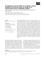
IEC 61508 is a generic standard which deals with the above. It can be used on its own or as
a basis for developing industry-sector-specific standards (Chapters 8e10). In attempting to
fill the roles of being both a global template for the development of application-specific standards and a standard in its own right, it necessarily leaves much to the discretion and interpretation of the user. IEC 61511 is a simplified form of IEC 61508 catering for the more consistent
equipment architectures found in the process industries.
One should bear in mind that the above documents are, largely, nonprescriptive guidance and
a large amount of interpretation is required on the part of the user. There are few absolute right/
wrong answers and, as always, the judgment of the professional (i.e., chartered) engineer must
always prevail.
It is also vital to bear in mind that no amount of assessment will lead to enhanced integrity
unless the assessment process is used as a tool during the design cycle.
Now read on!
The 2010 Version of IEC 61508
The following is a brief summary of the main changes which brought about the 2010 version.
Architectural Constraints (Chapter 3)
An alternative route to the “safe failure fraction” (the so-called route 1H) requirements was
introduced (known as Route 2H).
Route 2H allows the “safe failure fraction” requirements to lapse providing that amount of
redundancy (so-called hardware fault tolerance) meets a minimum requirement AND there
is adequate user-based information providing failure rate data.
The meaning of “safe” failures in the formula for safe failure fraction was emphasized as referring only to failures which force a “safe” state (e.g., spurious trip).
Security (Chapter 2)
Malevolent and unauthorized actions, as well as human error and equipment failure, can be
involved in causing a hazard. They are to be taken account of, if relevant, in risk assessments.
Safety Specifications (Chapter 3)
There is more emphasis on the distinct safety requirements leading to separately defined design
requirements.
Digital Communications (Chapter 3)
More detail in providing design and test requirements for “black box” and “white box”
communications links.
ASICs and Integrated Circuits (Chapters 3 and 4)
More detailed techniques and measures are defined and described in Annexes to the Standard.
xvii
xviii
The 2010 Version of IEC 61508
Safety Manual (Chapters 3 and 4)
Producers are required to provide a safety manual (applies to hardware and to software) with
all the relevant safety-related information. Headings are described in Annexes to the Standard.
Synthesis of Elements (Chapter 3)
In respect of systematic failures, the ability to claim an increment of one SIL for parallel
elements.
Software Properties of Techniques (Chapter 4)
New guidance on justifying the properties which proposed alternative software techniques
should achieve in order to be acceptable.
Element (Appendix 8)
The introduction of a new term (similar to a subsystem).
The 2016 Version of IEC 61511
The following is a brief summary of the main changes which have brought about the 2016
update.
The term “application software” has been changed to “application program.”
The “grandfather clause” in ISA84 has been added.
Procedures for competence are called for.
It is possible to claim up to one risk reduction layer within the process control system for the
same hazard event when it is also the initiating event and two risk reduction layers if it is not
part of the initiating cause (see Chapter 8).
The Architectures table has been revised and the term “safe failure fraction” deleted (see
Chapter 8).
New clause on security vulnerabilities added.
Requirements for “application program” development have been significantly reduced by
removing repetition with the wider requirements.
The total risk reduction for both the Basic Process Control System and Safety Instrumented
Systems shall not be <10,000:1.
The Safety Manual (IEC 65108 2010) is emphasized.
xix
This page intentionally left blank
Acknowledgments
The authors would like to thank all the staff of ESC Ltd for suggestions and support and,
in particular, Simon Burwood, Ron Bell, and Mohammed Bhaimia for their detailed
contributions.
The authors are very grateful to Mike Dodson, Independent Consultant, of Solihull, for
extensive comments and suggestions and for a thorough reading of the earlier manuscripts.
Thanks, also, to:
Dr Tony Foord for constructive comments on Chapters 3 and 4 and for help with the
original Chapter 14.
Mr Paul Reeve for comments on Chapter 7.
Mr Stephen Waldron, of JCB, and Mr Peter Stanton, of Railtrack, for help with Chapter 10.
xxi
This page intentionally left blank
PART A
The Concept of Safety Integrity
In the first chapter we will introduce the concept of functional safety and the need to express
targets by means of safety integrity levels. Functional safety will be placed in context, along
with risk assessment, likelihood of fatality, and the cost of conformance.
The life-cycle approach, together with the basic outline of IEC 61508 (known as BS EN 61508
in the UK), will be explained.
1
This page intentionally left blank