Ảnh hưởng của tường chèn tới phản ứng của hệ khung bê tông cốt thép chịu động đất tt tiếng anh
Bạn đang xem bản rút gọn của tài liệu. Xem và tải ngay bản đầy đủ của tài liệu tại đây (1.38 MB, 27 trang )
MINISTRY OF EDUCATION AND TRAINING
NATIONAL UNIVERSITY OF CIVIL ENGINEERING
Phan Van Hue
EFFECTS OF MASONRY INFILLS ON THE
RESPONSES OF REINFORCED CONCRETE FRAME
STRUCTURES UNDER SEISMIC ACTIONS
Major: Civil Engineering
Code: 9580201
SUMMARY OF DOCTORAL DISSERTATION
Ha Noi - 2020
The Dissertation has been completed at
the National University of Civil Engineering
Academic advisor: Assoc. Prof. Dr. Nguyen Le Ninh
Examiner 1: Prof. Dr. Nguyen Tien Chuong
Examiner 2: Assoc. Prof. Dr. Nguyen Ngoc Phuong
Examiner 3: Dr. Nguyen Dai Minh
The doctoral dissertation will be defended before Doctoral Defence
Committee held at the National University of Civil Engineering at
……… on ……………….…………, 2020.
This Dissertation is available for reference at the Libraries as
follows:
- National Library of Vietnam
- National University of Civil Engineering’s Library
1
PREFACE
1. REASON FOR SELECTING THE TOPIC
Earthquake researches and engineering site observations over the past
seven decades show that masonry infills (MIs) significantly affect
response of the surrounding frame structures under seismic actions. The
modern seismic standards, including TCVN 9386:2012, admit this
phenomenon, but the design regulations for the infilled frames still have
many shortcomings:
(i) Conflicts between design of the whole structure (ignoring the
interactive forces with the MIs) and design of structural members locally
(considering the interactive forces with the MIs);
(ii) The models to calculate the infilled frames are unclear and
uncompleted.
Therefore, the study on "Effects of masonry infills on the responses of
reinforced concrete frame structures under seismic actions" is necessary
and meaningful.
2. RESEARCH PURPOSES
(i) To establish the behavior model of the MIs and to employ this
model to determine the seismic behavior of infilled frames;
(ii) To study how to control the failure mechanisms of reinforced
concrete (RC) frames under seismic actions, considering the interaction
between the frame and the MIs;
(iii) To study the effects of the MIs on the control of the local response
of RC frame columns under seismic actions.
3. RESEARCH OBJECTS AND SCOPE OF WORK
3.1. Research objects
Multi-storey monolithic RC frames with MIs in the frame plane:
(i) The frames are designed according to the modern seismic
conception;
(ii) Unreinforced MIs (solid and hollow clay bricks, AAC bricks)
without openings are constructed after the hardening of the RC frames.
The MIs are in contact with the frame (i.e. without special separation
joints) but without a structural connection to it.
3.2. Scope of work: (i) Impacts are in the frame plane;
(ii) The aspect ratio of MIs: αm = hm/lm ≤ 1.0
4. SCIENTIFIC BASIS OF THE TOPIC
(i) Research results of infilled frames in the last seven decades;
(ii) The modern seismic design conception;
(iii) Regulations on designing the RC frames subjected to earthquakes
in some common building codes worldwide, including Vietnam.
2
5. RESEARCH METHODOLOGY
Theoretical research and numerical simulation analysis are used.
6. NEW CONTRIBUTIONS OF THE DISSERTATION
(i) Established the nonlinear behavior model of the MIs and employed
this model to determine the seismic behavior of infilled RC frames;
(ii) Established the condition to control failure mechanisms of the RC
frames and proposed the method to design RC frames when considering
the interaction with the MIs based on the modern seismic design
conception;
(iii) Proposed a method to determine the interactive forces between
the frame and the MIs as well as a method to design RC frame columns
in shear considering these interactive forces.
7. LAYOUT OF DISSERTATION
The thesis consists of preface, four chapters, and conclusions,
presented in 116 pages with 29 tables, 55 figures, 149 references
(Vietnamese: 10, English, Romanian: 139). The appendix has 21 pages.
CHAPTER 1
INTERACTION BETWEEN FRAMES AND MASONRY INFILLS AND
DETERMINATION OF RESPONSES OF THE MASONRY INFILLED RC
FRAMES UNDER LATERAL IMPACT
1.1. INTRODUCTION
Contrary to the previous conception that considers MIs as nonstructural elements, the field observation results showed that MIs are the
cause of failures: columns, beam-column joints, and the collapse of
buildings, etc. under seismic action. This issue has attracted many studies
worldwide.
1.2. INTERACTION BETWEEN FRAMES AND MASONRY INFILLS AND
BEHAVIOR OF MASONRY INFILLED RC FRAMES UNDER LATERAL
IMPACT
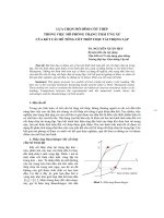
1.2.1. Interaction between frames and MIs under lateral impact
The behavior of MIs in the frames
under lateral impact can be divided
into two stages. At the first stage,
before the frame-MI contact surfaces
are cracked, the structure behaves like
a)
b)
a monolithic vertical cantilever; and at
Figure 1.3. The behavior of MI RC
the second stage after the contact
frames and interactive forces in the
surfaces are cracked at the unloaded
contact regions
corners (Figure 1.3a). In the remaining
contact regions, interactive forces appear (Figure 1.3b).
3
1.2.2. Consequences of frame-MI interaction for the behavior of MI RC
frames
1.2.2.1. RC frames are designed not according to the seismic standards
The impact of the frames-MIs interaction forces has resulted in failure
of MIs and of the frame components.
1. Types of failure in MIs: (i) Shear cracking (cracking along mortar
joints, stepped cracks or horizontal sliding; diagonal cracks); (ii)
Compression failure (failure of the diagonal strut; corner crushing).
2. Types of failure of RC frames: (i) Flexural failure (at member ends;
in span length); (ii) Failure due to axial force (yielding of the longitudinal
reinforcement; bar anchorage failure); (iii) Shear failure of columns; (iv)
Beam-column joint failure.
1.2.2.2. The RC frames are designed according to modern seismic
standards
The extensive experimental researches by the authors: Mehrabi et al.
(1996), Kakaletsis and Karayannis (2008), Morandi et al. (2014-2018),
Basha (2017) gave the failure types as follows:
1. Types of failures in MIs: Strong MIs-strong frames: diagonal sliding
shear and compression failure. Weak MIs-strong frames: sliding shear
failure along the diagonal or in the midheight of MIs.
2. Types of failure of RC frames:
a) Column: Plastic hinges appear at the ends of columns; shear cracks
occur simultaneously with flexural cracks.
b) Beams: Flexural and shear cracks rarely appear. Frame beams
behave more stiffly when considering the interaction with MIs.
1.3. MODELING OF BEHAVIOR OF MIs UNDER LATERAL LOADING
1.3.1. Behavior models of MIs in frames
1.3.1.1. Macromodels
Replace MIs with one or
more equivalent diagonal
struts.
1. Single-strut models
(Figure 1.8): parameters of
diagonal struts: width wm and
thickness tm (tm is equal to
a) Deformation due to
b) The equivalent diagonal
MI’s thickness).
lateral force
strut model
2. Multiple-strut models:
Figure 1.8. The equivalent diagonal strut model
Divide a diagonal strut into
multiple equivalent struts (Figures 1.9 and 1.10).
4
1.3.1.2. Micromodels
Based on finite element methods (Figures 1.13 and 1.14).
1.3.1.3. Remarks: The
single strut macromodels
are simple, easy to apply.
They give approximate
results, but no results for
local
effects.
The Figure 1.9. Chrysostomou’s
Figure 1.10.
micromodels are more
model
El-Dakhakhni’s model
accurate, but calculation
volume is large and it is difficult to determine the model's parameters.
1.3.2. Main results achieved in macromodeling
1.3.2.1. Results achieved in determining the diagonal width wm
1. In the world:
a) The approaches for
determining wm depend on
the geometric properties of
MIs:
Figure 1.13. Mallick
Figure 1.14. Mehrabi
and Severn’s model
and Shing’s model
The following authors
have given the expressions
for determining wm by a fixed fraction of the length of the panel diagonal
dm: Holmes [1/3] (1961), Smith [0.1÷0.25] (1962), Moghaddam and
Dowling [1/6] (1988), Smith and Coull [1/10] (1991), Paulay and
Priestley [0.25] (1992), Angel et al. [1/8] (1994), Fardis [0.1÷0.2] (2009),
etc. (The values in [] indicate the proposed wm/dm ratios).
b) The approaches for determining wm depend on both the geometric
and mechanical properties of frames and MIs:
The following authors have proposed the methods for determining wm
in this way: Mainstone (1974); Abdul-Kadir (1974), Henry (1998);
Nguyen Le Ninh (1980); Bazan and Meli (1980); Liauw and Kwan
(1984); Decanini and Fantin (1986); Govindan (1986); Dawe and Seah
(1989); Decanini et al. (1993); Durrani and Luo (1994); Flanagan and
Bennet (2001); Al-Chaar (2002); Tucker (2007); Amato et al. (2009);
Tabeshpour et al. (2012); Chrysostomou and Asteris (2012); Turgay et al.
(2014), etc.
2. In Vietnam:
Ly Tran Cuong (1991) and Dinh Le Khanh Quoc (2017) proposed the
methods of determining wm in the direction of group b).
5
3. Remarks on the results achieved in determining wm:
The width wm depends on: (i) The mechanical and geometric
properties of components of infilled frames; (ii) The degree of
deterioration of their strength and stiffness; (iii) Time of determining wm.
Therefore, values of wm are completely different from the authors.
Among the proposed methods, the method proposed by Nguyen Le
Ninh (1980) can be applied to consider all the above factors.
1.3.2.2. Results achieved in establishing a simple nonlinear behavior model
of MIs
Many
authors
studied this model:
Decanini, Bertoldi and
Gavarini
(1993);
Panagiotakos and Fardis
(1994); Kappos and
Figure 1.15. Model of Decanini et al.
Stylianidis
(1998);
Chronopoulos (2004); Stavridis et al. (2017), etc. The curve shapes of
these models are basically the same as Figure 1.15. However, the model
parameters including the stiffness and strength of the MIs are different.
Although there are many advantages, their application is very limited.
1.4. EFFECTS OF FRAME-MI INTERACTION IN THE SEISMIC
STANDARDS
1.4.1. The rules take into account the influence of MIs
TCVN 9386:2012 and EN 1998-1:2004; FEMA 356 (2000); ASCE
41-13 (2013) and ASCE 41-17 (2017); NZSEE (2017) provided the rules
to consider the effects of MIs on behavior of RC frames under seismic
action.
1.4.2. Remarks on the rules in the design standards
• All standards state that MIs have detrimental effects on the frames,
but they separate the local response calculation from the overall
calculation. The design rules of beams, columns and beam-column joints
do not take into account the influence of interactive forces with MIs, but
when examining the columns in shear, this interactive forces must be
considered.
• When calculating the local response, the standards require the use of
a single diagonal strut model, but there are no instructions on how to set
the model (especially TCVN 9386:2012), so it is difficult to implement.
1.5. REMARKS ON CHAPTER 1
1. The frame-MI interaction causes the typical types of failure in RC
frames designed according to the modern seismic conception: flexural
6
and shear failures either at the ends or in the middle of columns; beams
are often increased in stiffness, and MIs are often failed by sliding shear
along the diagonal or in the midheight of MI and diagonal compression.
2. The simple model using an equivalent diagonal strut is relevant to
determine the overall response of the infilled frames.
3. While recognizing the important influence of the frame-MIs
interactive forces, the standard design regulations of infilled frames are
still inadequate and unclear.
CHAPTER 2
MODELING OF NONLINEAR BEHAVIOR OF MASONRY INFILLED RC
FRAMES UNDER SEISMIC ACTIONS
2.1. SELECTING THE METHODS TO MODEL MASONRY INFILLED RC
FRAMES
From the literature review, the following models are selected for the
analysis of infilled frames: a simple model to simulate bending behavior
in critical regions of the RC frame and the equivalent diagonal strut model
to simulate the behavior of MIs.
2.2. BEHAVIOR MODEL OF THE RC FRAMES
2.2.1. At the material level: Use the behavior models of concrete and
reinforcement specified in EN 1992-1-1:2004.
2.2.2. At structural element level: Use the concentrated-plasticity
modeling approach. The behavior of plastic hinges is controlled through
the modified Takeda model and its force-displacement curve is taken
according to ASCE 41-13 (Figure 2.2).
a)
b)
c)
Figure 2.2. a) Plastic
b) The modified Takeda
c) Generalized M–θ
deformation concentrated
hysteresis rule
relationship at plastic
on the frame components
hinges of RC frame components
2.3. ESTABLISH THE NONLINEAR BEHAVIOR MODEL OF THE MIs IN
RC FRAMES
2.3.1. Setting up the force-displacement relationship of the model
The behavior of the MIs in the frame is modeled as a curve shown in
Figure 2.3. In the frame model, the MIs are shown in Figure 2.4.
7
Figure 2.3. The force-displacement relationship Figure 2.4. Position of plastic
of the MI’s behavior model
hinges in the model of infilled frames
2.3.2. Define the basic parameters of the model
2.3.2.1. The stiffness of MIs
According to Nguyen Le Ninh (1980), the width wm = e m (1− n ) wm 0 (2.1)
with wm 0 =
dm
=
(2.2); λh
( λh h + λl l + k )
Em tm lm
=
; λl
4 Ec I c hm2
4
4
Em tm hm
(2.3)
4 Ec I b lm2
where n = H/Hu, H is the lateral force and Hu is the lateral force at the
time when MI reaches the ultimate strength; m and k are coefficients
depending on the type of masonry; other parameters indicate the
geometric and mechanical properties of frames and MIs (Figure 1.8).
From the width wm, determine the stiffness of the MI at the beginning
of the crack (2.4) and when reaching to the ultimate strength (2.5):
K my
e0.4 m wm 0 tm Em
wm 0 tm Em
∗
K my =
cos 2 θ
cos 2 θ =
=
(2.4); K mu
(2.5)
dm
dm
e0.4 m
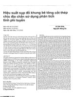
2.3.2.2. The strength of the MIs
1. The ultimate strength of masonry infill Vmu is determined from the
condition Vmu = min (Vms ,Vmc ) (2.6), where:
a) Vms is the sliding shear strength of MIs selected from approaches of
following authors: Rosenblueth (1980); Smith and Coull (1991); Paulay
and Priestley (1992); Decanini et al. (1993); Panagiotakos and Fardis
(1994), Fardis (2009); Zarnic and Gostic (1997); FEMA 356 (2000), AlChaar (2002), ASCE 41-06, ASCE 41-13; Galanti et al. (1998), EN 19981:2004; FEMA 306 (1998); EN 1996-1-1:2005; according to TCVN
5573:2011 (2.10).
Vms =
f bs tm lm
1 − 0.72n1µ tgθ
(2.10)
8
b) Vmc is the diagonal compression strength of MIs selected from
approaches of following authors: Smith and Coull (1991); Decanini et al.
(1993); Galanti et al.
(1998); FEMA 306; AlChaar (2002); Tucker
(2007); ASCE 41-13.
In order to select the
appropriate strengths for
MI’s model, comparative
analyses are performed on
the infilled RC frame
consistent with the object
and objectives of the
research. The results are
Figure 2.9. Variation of Vms determined by different
the curves representing
approaches associated with hm/lm
relationships of Vms and
Vmc associated with the common
hm/lm ratios of MIs in Figures 2.9
and 2.10. Since then, choose the
strength Vms according to TCVN
5573:2011 (2.10) and the
strength Vmc according to ASCE
41-13:
Figure 2.10. Variation of Vmc determined by
h
Vmc = f mc m tm cos θ (2.11)
different approaches associated with hm/lm
3
2. The yielding strength of the masonry infill Vmy is selected from
approaches of following authors: Nguyen Le Ninh (1980), Dolsek and
Fajfar (2008); Decanini et al. (1993); Panagiotakos and Fardis (1994);
Saneinejad
and
Hobbs
(1995), FEMA 306; Tucker
(2007); Stavridis (2009).
Similarly, from the results in
Figure 2.12, choose Vmy =
0.6Vmu (2.12) as suggested by
Nguyen Le Ninh and Dolsek
and Fajfar (2008).
Figure 2.12. Variation of Vmy determined by
3. The residual strength of
different approaches associated with hm/lm
the masonry infill Vmr:
(2.13)
0 ≤ Vmr ≤ 0.1Vmy
9
2.3.2.3. Steps to establish the force-displacement curve of the model
Step 1. Determine Kmy using (2.4). Step 2. Determine Vmu using (2.6).
∗
Step 3. Determine ∆ mu =
(2.14). Step 4. Determine Vmy using
Vmu K mu
(2.12). Step 5. Determine ∆ my =
Vmy K my (2.15). Step 6. Determine Vmr
using (2.13). Step 7. Determine
∆ mr =
∆ mu + (Vmr − Vmu ) / K mr (2.16)
2.3.2.4. Axial nonlinear response of
equivalent diagonal strut
Using
the
stress-deformation
relationship of masonry proposed by
Kaushik, Rai and Jain (2007) (Figure
Figure 2.13. Idealized stress-strain
2.13).
relationship for masonry under
2.3.3. Calibrate the behavior model of
uniaxial compression
the MI
Calibration of the proposed model is performed based on the experimental
data of infilled RC frame models designed according to EC8 and EC2 of
Kakaletsis and Karayannis (2008) and Morandi, Hak and Magenes (20142018).
2.3.3.1. Kakaletsis and Karayannis (2008)
a) Weak MI (S)
b) Strong MI (IS)
Based on the parameters of the
experimental models, we establish the
behavior models of the MIs based on the
steps in section 2.3.2.3 (Figure 2.16).
Using these models together with the
behavior models of the RC materials and
structural elements selected in section
2.2, performing a nonlinear pushover
analysis of the experimental frame
models. The capacity curves obtained
from analyses are compared with the
experimental
force-displacement
envelopment (Figure 2.18). The results
show a good fit between them.
Figure 2.16.
Force displacement
relationship of
the proposed
MIs’ models
Figure 2.18. Comparison between
experimental results and analytical
results using the proposed method
10
2.3.3.2. Morandi et al. (2014-2018)
Figure 2.20. Force - displacement
relationship of the proposed MI’s
model
Similarly, set up a behavior
Figure
2.21.
Comparison
between
model of the MI using the
experimental results and analytical results
proposed method (Figure 2.20)
using the proposed method
and perform a nonlinear pushover
analysis of the experimental frame models. The results show that the capacity
curves obtained from the analyses are quite consistent with the experimental
envelopment (Figure 2.21).
2.4. REMARKS ON CHAPTER 2
A simple model is established to simulate the behavior of the MIs in
RC frames taking into account the decrease in strength and stiffness of
frame and MIs. The verification results on the infilled RC frame models
designed according to the current seismic conception exhibit good results.
So, the calibration of the model is not necessary.
CHAPTER 3
EFFECTS OF MASONRY INFILLS TO THE CONTROL OF THE FAILURE
MECHANISM OF RC FRAME STRUCTURES UNDER SEISMIC ACTIONS
3.1. MODERN CONCEPTION AND DESIGN RULES FOR FRAMES IN THE
CURRENT SEISMIC DESIGN STANDARDS
3.1.1. Modern conception in design of structures for earthquake
resistance
According to the current seismic conception, the design purpose of a
building is to protect directly both human life and social properties. When
a strong earthquake occurs, the buildings are allowed to work beyond the
elastic limit, but they are not collapsed suddenly.
3.1.2. Basic design principles according to modern seismic conception
From the aforementioned goals, the structure must be designed to
experience plastic failure, and shear failure must happen after flexural
failure when a strong earthquake occurs.
11
3.1.3. Design RC frames according to current seismic standards
To carry out the above design principles, the capacity design method
is used. By using this method, the forces used to design a frame must be
as follows, for example, according to TCVN 9386:2012 (the “so-called”
basic design principle of strong columns - weak beams):
a) Beam: The bending moment M and the axial force N are taken from
the results of structural analysis, while the shear force Q is determined
from the bending resistance of the beam.
b) Column: The bending moment M is redefined from the following
condition:
M Rc ≥ 1.3 M Rb
(3.1)
∑
∑
in which: ΣMRc is the sum of the minimum design values of the moment
resistances of the columns framing to the joint, taking into account the
column axial force N in the seismic design situation; ΣMRb is the sum of
the design values of the moment resistances of the beams framing to the
joint.
Shear force Q is redefined from the flexural strength of columns.
Remarks: (i) The frame design process must follow a very strict
process; (ii) Frame design rules do not take into account frame-MI
interaction.
3.2. EFFECTS OF MIs TO THE BEAM RESPONSE
Experimental studies on the infilled frames show that the interactive
forces with the MIs make the beams behave more stiffly than that of bare
frames. To clarify this phenomenon, consider a RC frame without MI
(bare frame) as shown in Figure 3.2a. The external force H causes the
bending moment at the ending section C of the beam:
Ih
Hh 3ω
ω= b
(3.2)
where:
(3.3)
M bC , H =
Icl
2 6ω + 1
a) Bare frame;
b) Infilled frame;
c) Equivalent infilled frame
Figure 3.2. Models for calculation of the frame
The curvature of the beam at the end C has the following value:
M bC , H
Hh 3ω
(3.4)
=
ρbC , H =
Ec I b
2 Ec I b 6ω + 1
12
When MI is available, the model to calculate an infilled frame is as
shown in Figure 3.2b, where Rm is the compression force in the diagonal
strut with the area of cross-section of wmtm. Replace the model in Figure
3.2b with the equivalent model in Figure 3.2c (Vm is the horizontal
projection of the compression force Rm in the diagonal strut). With this
model, we have the moment and curvature of the beam when taking into
account the interactive force with MIs:
( H - Vm ) h 3ω
(3.5)
M bC , H -Vm =
2
6ω + 1
ρbC , H -Vm
=
M bC , H -Vm ( H - Vm )h 3ω
=
< ρbC , H
2 Ec I b 6ω + 1
Ec I b
(3.6)
Thus, the interaction with MIs makes the beam stiffer. Let Ibm ( >Ib) be
the equivalent moment of inertia of the beam when considering
interaction with MIs. Similarly (3.4), we will get the curvature of the
beam in this case:
*
M bC
I h
3ωm
Hh
,H
*
(3.7), where: ωm = bm
(3.8)
ρbC , H =
=
Icl
Ec I bm 2 Ec I bm 6ωm + 1
Considering (3.3) and (3.8), we obtain the coefficient k=
Ib
I bm ωm
=
Ib
ω
(3.9) which indicates the increase in moment of inertia (flexural stiffness)
of the beam when interacting with MIs.
Balancing the curvatures (3.6) and (3.7), we establish the relationship:
6ωm + 1
H
=
6ω + 1 H − Vm
(3.11)
From the relationship between horizontal force H and Vm established
on the basis of the calculation diagrams in Figures 3.2b, 3.2c, and from
(3.11), we set the ratio ωm/ω. With this result, determine the coefficient
kIb (3.9) at the ultimate time (wm = wm0 when n = 1.0 see Chapter 2) when
considering the interaction with MIs:
k Ibu =
I bmu
h3 w m 0tm Em cos 2θ 3ω + 2
= 1+
Ib
Ec I c d m
72ω
(3.18)
Equation (3.18) shows that, when considering the interaction with
MIs, the moment of inertia of the beam Ibmu is increased by kIbu times:
Ibmu = kIbuIb. This means that the cross-section height of the beam is
increased to hbmu = hb 3 k Ibu (3.19) called the equivalent cross-section
13
height. The increase in the cross-section height of the beam leads to an
+
−
and negative M Rb
for
increase in its bending resistance both positive M Rb
the considered sense of the seismic action. In the general case, at any
column-beam joint:
−
+
−
+
M Rbmu =M Rbmu
+ M Rbmu
> M Rb =M Rb
+ M Rb
(3.21)
∑
∑
where ΣMRbmu and ΣMRb are the sums of the design values of the moments
of resistance of the beams framing the joint when considering and not
considering the interaction with MIs for the considered sense of the
seismic action, respectively.
Thus, when considering the interactive forces with MIs, the moments
of resistance of the beams are increased by the following coefficient:
+
M Rbmu M Rbmu
+ M Rbmu
(3.22)
=
k Mb =
> 1
+
M Rb
M Rb
+ M Rb
∑
∑
3.3. METHODS TO DESIGN THE RC FRAMES FOR EARTHQUAKE
RESISTANCE WHEN CONSIDERING THE INTERACTION WITH THE MIs
3.3.1. Condition to control the failure mechanism of the RC frames
From the above mentioned research results, in cases taking into
account of the interaction with MIs, the condition to control the plastic
failure mechanism (3.1) of a frame in TCVN 9386:2012 may not be
M Rb in the right-hand side is increased via kMb. This
accurate, because
∑
also means that the columns may be failed before the beam and the soft
story failure mechanism may appear unintentionally.
Therefore, to let the infilled frames be failed plastically as the design
purpose, the design conditions (3.1) shall be rewritten as follows:
M Rcmu ≥ 1.3kMb M Rb
(3.23)
∑
∑
in which ΣMRcmu is the sum of the minimum design values of the moment
resistances of the columns framing to the joint, taking into account the
column axial force N in the seismic design situation at the ultimate limit
state of MIs. With this condition, whether the MIs are available or not,
the design principle of "strong columns - weak beams" will be guaranteed
and the frames will be failed in plastic mechanisms under strong
earthquakes.
3.3.2. The method to design RC frame structures under seismic actions
when considering the interaction with the MIs
Step 1. Design and detail of RC beams in accordance with current
seismic design standards.
14
Step 2. Determine kIbu in (3.18) and the equivalent cross-section height
of beam hbmu in (3.19). Then determine the moment resistances of the
−
and
equivalent beams when considering the interaction with MIs M Rbmu
+
M Rbmu
. Determine kMb in (3.22).
Step 3. Determine the bending moment to design the columns
M
∑ Rcmu in the proposed condition (3.23). Then design and detail the
longitudinal reinforcement of columns according to the rules of the
current seismic design standard.
3.4. CALCULATION EXAMPLES
3.4.1. The calculation data
A 3-storey cast-in-place RC frame building with dimensions as shown
in Figure 3.4. The exterior beams of 25x45 cm, the interior beams of
25x50 cm, the slab thickness of 15 cm.
Materials: concrete B30, longitudinal reinforcement type CB400-V,
stirrup reinforcement type CB240-T.
The KB and KE frames are filled with solid brick masonry 20 cm
thick, burnt clay bricks M100, cement mortar M75.
Vertical load (permanent load g and imposed load q) at each floor
(including roof): g + ψ2q = 9 kN/m2.
The building is built in a region with the reference peak ground
acceleration on type A ground (rock) agR = 0.1097g, ground type D,
importance factor γI = 1.2; ductility class medium (DCM) according to
TCVN 9386:2012.
a) Plan view of the typical floor
b) Elevation of the frame
Figure 3.4. Models for the frame structure
3.4.2. Design the RC frame structures according to the regulations of
TCVN 9386:2012
The reinforcement details of typical frame KE are shown in Figure
3.5.
15
Figure 3.5. Reinforcement details of frame KE
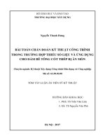
3.4.3. Determine responses of frame KE designed according to TCVN
9386: 2012
Figure
3.6.
Behavior of frame
KE
designed
according
to
TCVN 9386:2012
a) Step 6
b) Step 22
Using nonlinear pushover
analysis is to determine
responses of frame KE.
Behavior
models
of
materials
and
frame
components are taken from
EC2 and ASCE 41-13. The
analysis results show that the
frame is failed in agreement
with the plastic mechanism
as the design goal set out
(Figure 3.6). The capacity
curve is shown in Figure 3.7
(solid line).
c) Step 48
d) Step 102
Figure 3.7. Capacity curves of frame KE
in different cases
16
3.4.4. Determine responses of frame KE designed according to TCVN
9386:2012 when considering the interaction with MIs
Calculation results for force-displacement relations of the MIs are
shown in Figure 3.8.
a) 1st-floor
b) 2nd to 3rd floors
Figure 3.8. Force-displacement relationship in the behavior model of MIs
The pushover analysis in Figure 3.10 shows that the plastic
deformation process starts from the MIs to beams and the bases of
columns on the first floor. The capacity curve (dashed line) in Figure 3.7
shows that the frame stiffness drops suddenly and varies irregularly when
the base shear force reaches its maximum value of V = 626.27 kN and ∆
= 0.023 m in step 10 because the MIs on the first and second floors are
failed considerably. Until the target displacement ∆ = 4% H = 0.36 m
(step 108) is achieved, the plastic deformations are almost focused on the
bases of columns on the foundation surface and the top of columns on the
first floor, the MIs on the first floor are no longer capable of bearing
(Figure 3.10). The infilled RC frame is failed in agreement with the “soft
storey” mechanism.
a) Step 3
b) Step 10
c) Step 15
d) Step 108
Figure 3.10.
Behavior
of
frame KE when
considering
the interaction
with MIs
Comparing the capacity curves of frame KE in Figure 3.7 (without
considering (solid lines) and considering (dashed lines) the interaction
with MIs) shows that the interaction with MIs has greatly increased the
stiffness, horizontal bearing capacity, and energy dissipation capacity of
the frame in the initial elastic phase.
3.4.5. Design and detail the RC frame structures considering the
interaction with MIs using the proposed method
The design of the frame structure shown in Figure 3.4 is implemented
using the method proposed in section 3.3.2.
17
Step 1: Calculate beam reinforcement of frame KE and calculate their
flexural resistance MRb as design results in section 3.4.2 (Figure 3.5).
Step 2: Determine kIbu = 2.508 and the equivalent cross-section height
hbmu = 680 mm, thereby determine bending resistance of the beams and
the coefficient kMb = 1.14.
Step 3: Determine the required bending moment to design the columns
yc
from the proposed condition (3.23), from which design and
M Rcmu
∑
arrange longitudinal reinforcement of the columns. Compared with the
standard design results (Figure 3.5), the cross-section height of columns
on the first floor (C1 and C4) must be increased by 50mm while the
reinforcement of all columns remains the same.
Figure
3.11.
Behavior of frame
KE designed using
the
proposed
condition (3.23)
a) Step 11
b) Step 17
c) Step 113
Performing pushover analysis is to determine responses of infilled frame
KE with behavior models of materials, structural members, and MIs used in
the calculation example in section 3.4.4. The analysis results show that the
frame designed using the proposed method isn’t failed corresponding to the
soft storey mechanism (Figure 3.11). The capacity curves in Figure 3.7 show
that frame KE designed using the proposed method with the condition (3.23)
(dashed double-dot line) has superior behavior compared with the case
designed according to the condition (3.1) of TCVN 9386:2012.
3.5. REMARKS ON CHAPTER 3
1. The increasing coefficients of flexural stiffness kIbu and flexural
resistance kMb of beams are quantified when considering the interaction
with MIs.
2. On this basis, the condition that controls failure mechanism (3.23)
is proposed to replace the condition (3.1) of TCVN 9386:2012 which is
no longer accurate when considering the interaction with MIs. Then a
method to design RC frame structures for earthquake resistance is
proposed.
3. Specific calculation examples have demonstrated the reliability of
the performed theoretical research: the model of MIs, the method to
design RC frame structures for earthquake resistance when considering
the interaction with MIs, etc.
18
CHAPTER 4
CONTROL OF LOCAL FAILURES OF RC FRAMES UNDER SEISMIC
ACTIONS CONSIDERING THE INTERACTION WITH THE MIs
4.1. CONTROL OF LOCAL FAILURES OF RC FRAMES IN CURRENT
SEISMIC DESIGN STANDARDS
4.1.1. Control of shear failure in RC frames
Shear failure is a brittle failure mode, so
it must be prevented, and is not allowed to
occur before flexural failure. For frame
columns, according to TCVN 9386:2012,
the design shear force is determined from
the bending resistance of the column (called Figure 4.1. Diagram of
determining column shear force
the capacity shear force) (Figure 4.1).
M
M
γ Rd M Rc ,1 ∑ Rb + M Rc ,2 ∑ Rb
∑ M Rc
∑ M Rc
1
2
VCD , c =
(4.3)
lcl , c
where lcl,c is the clear length of the column; MRc,i is the design value of
the column moment resistance at the end i (i = 1, 2) in the sense of the
seismic bending moment under the considered sense of the seismic action;
( M Rb / M Rc )i ≤ 1 where ∑MRc and ∑MRb are the sums of the design
∑
∑
values of the moment resistances of the columns and the sum of the design
values of the moment resistances of the beams framing into the joint,
respectively; γRd is the factor accounting for overstrength. The values of
MRc,i and ∑MRc should correspond to the column axial force in the seismic
design situation for the considered sense of the seismic action.
4.1.2. Verification of column shear failure in seismic standards
TCVN 9386:2012 and EN 1998-1:2004 require checking and detailing
of columns in shear considering the interaction with MIs through the
(4.4)
condition:
VRd , c ≥ VEd , c ,lc
Figure
4.2.
Acting shear on
the
columns
due to MIs
19
in which VRd,c is the shear resistance at the ends of the columns designed
according to the standard; VEd,c,lc is the increased design shear due to the
horizontal strut force acting at the column ends (Figure 4.2):
VEd , c ,lc = min (VEd , c , ms ;VEd , c , M )
(4.5)
= V=
Am f mv
(i) VEd , c , ms
m
where:
(4.6)
with Am = tmlm and fmv is the shear strength of the MIs;
(ii) VEd , c , M = 2γ Rd M Rd , c lc
(4.7)
Other countries' standards are the same.
4.1.3. Remarks on the rules for verification of shear failure
1. There is a high agreement among the
standards: the interaction with the MIs is not
considered when designing overall the frame
but the interactive forces with the MIs are
considered when verifying the columns in
shear.
2. The instructions in TCVN 9386:2012
and EN 1998-1:2004 are rather ambiguous,
Figure 4.3. The interactive
leading to various interpretations when they
forces between frame and MI
are applied, e.g. the diagonal strut width wm,
the length of contact regions lc, etc.
4.2. FRAME - MI INTERACTIVE FORCES AND LOCAL RESPONSE OF RC
COLUMNS UNDER INTERACTIVE FORCES
According to Nguyen Le Ninh, the contact
lengths zh and zl between the MI and the frame
change when the infilled frame is subjected to
lateral load. At the ultimate time of MI (n =
1.0):
zh 0 = β 0π 2λh and zl 0 = β 0π 2λl (4.14)
with:
β0 =
dm
wmk ( λh h + λl l + k )
(4.13)
Figure
4.4.
The
distribution of strut’s
force on frame’s elements
Along the contact regions zh and zl, interactive stresses which are
assumed to be linearly distributed appear, causing the force Rm in the
equivalent diagonal strut (Figure 4.3). According to Tassios et al. (1988),
it is possible to divide Rm into 3 parts as shown in Figure 4.4. At the
ultimate state of the MI (n = 1.0), the interactive forces at the contact
regions of column and beam with the MI are determined by the following
expressions (Figure 4.5):
20
qh 0 = 0.8Vmu zh 0
(4.17)
ql 0 = 0.4Vmu tgθ zl 0
(4.18)
where Vmu is the horizontal projection of
the force in the diagonal strut Rmu. From
the force qh0, determine the column shear
force due to the local interaction with the
MI (Figure 4.5):
Vc , mA =
qh 0 zh 0 qh 0 zh30 qh 0 zh40
− 2 +
(4.19)
2
4lcl ,c
10lcl3 ,c
q z3
q z4
Vc , mB =
− h 02 h 0 − h 0 3 h 0
4l
10lcl ,c
cl ,c
Figure 4.5. Local effects on columns
due to MIs
(4.20)
4.3. METHOD TO DESIGN THE RC COLUMNS IN SHEAR WHEN
CONSIDERING THE FRAME-MI INTERACTIVE FORCES
4.3.1. Condition to control the column shear failure
When considering the interactive forces with the MIs, the capacity
design shear of columns, VCD,c,m is determined in (4.3) in which ∑MRcmu
is determined by increasing kMb times using the proposed method in
section 3.3, Chapter 3. So it will be greater than VCD,c determined
according to TCVN 9386:2012. However, this increase in shear force is
only caused by the stiffening effect of the beams, not counting the
interactive forces between the MIs and the columns. Therefore, the design
shear of columns will be determined from the following proposed
condition:
VEd ,c , m = max(VCD ,c , m ;Vc , pt , m )
(4.23)
where Vc , =
Vc , pt + Vc , m (4.24) is the column shear force determined
pt , m
from structural analysis considering the local interaction with the MIs;
Vc,pt is the column shear force determined from the structural analysis
without considering the interaction with the MIs; Vc,m is the column shear
force due to the local interaction with the MIs determined by (4.19) and
(4.20).
The condition of controlling column shear failure in the case of
considering the interactive forces with the MIs is as follows:
(4.25)
VRd ,c , m ≥ max(VCD ,c , m ;Vc , pt , m )
where VRd,c,m is the shear resistance of the column when considering the
interaction with the MIs.
21
4.3.2. Method to design columns in shear when considering frame-MI
interactive forces
Continuing with the frame design steps proposed in section 3.3.2, the
design of columns in shear is carried out as follows:
Step 4. Determine the capacity design shear of columns VCD,c,m in (4.3)
from the result in step 3.
Step 5. Determine the interactive force qh0 in (4.17) and local shear
forces in columns Vc,mA, Vc,mB in (4.19) and (4.20).
Step 6. Determine VEd,c,m in (4.23) in which Vc,pt,m is taken from (4.24).
Step 7. Design and detail the columns in shear according to TCVN
9386:2012 and EN 1992-1-1:2004 from VEd,c,m in step 6.
Step 8. Check the columns in shear according to conditions (4.25).
4.4. CALCULATION EXAMPLES
4.4.1. Design of columns in shear according to TCVN 9386:2012
The analytical results in
the seismic design situation
produce the shear force
diagram Vc,pt in frame KE as
shown in Figure 4.6. From
the flexural strengths of
columns
and
beams
determined in the calculation
example in section 3.4.2,
calculate the capacity design
shears VCD,c of first floor
Figure 4.6. Shear force diagram of frame KE
determined from structural analysis in the
columns according to (4.3):
seismic design situation
VCD,c = 125.698 kN for
column C1 and VCD,c =
54.523 kN for column C4. From these capacity design shear forces,
identify the stirrup reinforcement of the column C1 (Ф8, spacing sd1 =
110 mm in the critical regions) and the column C4 (Ф8, spacing sd1 = 120
mm in the critical regions). The stirrup reinforcement details of the
columns are shown in Figure 3.5. Calculate the shear resistances of
column C1: VRd,c = 140.742 kN and column C4: VRd,c = 66.283 kN.
4.4.2. Design of columns in shear using the proposed method
From the section 4.3.2, the design is carried out as follows:
22
Step 4. Calculate the capacity shear force VCD,c,m using (4.3) in which
∑MRcmu was taken from step 3.
Results: column C1: VCD,c,m = 149.05 kN; column C4: VCD,c,m = 65.594
kN.
Step 5. Calculate the interactive force qh0 = 519 N/mm and the local
shear forces Vc,mA, Vc,mB caused by this force using (4.19) and (4.20).
Step 6. Calculate Vc,pt,m using (4.24) and design shear forces VEd,c,m
using (4.23).
Step 7. Detail and dimension of columns in shear from VEd,c,m in step
6. Results: column C1 – stirrup reinforcement Ф8, spacing sd1 = 130 mm
in critical regions and column C4 - stirrup reinforcement Ф10, spacing sd1
= 120 mm in critical regions.
Therefore, the stirrup spacing of column C1 increases from 110 mm
to 130 mm, while the stirrup diameter of column C4 increases from Ф8
to Ф10 compared with the design results according to TCVN 9386:2012
in section 4.4.1.
Step 8. The results of verification through the condition (4.25) show
that columns designed using the proposed condition and method ensure
shear resistances.
4.4.3. Verification of the shear strength of columns when considering the
interaction with the MIs in accordance with TCVN 9386:2012
4.4.3.1. Verification of the shear strength of columns designed according
to TCVN 9386:2012
To be objective in checking columns in shear, choose the width of the
diagonal strut wm = 0.125dm= 678 mm suggested by Fardis and fmv = 0.16
MPa according to Hak. From (4.6) determine VEd,c,ms = 149.6 kN for
columns C1 and C4 and from (4.7) determine VEd,c,M = 520.691 kN for
column C1 and VEd,c,M = 236.134 kN for column C4. The results of
verifying the condition (4.4) show that columns C1 and C4 on the 1st floor
of frame KE are all failed in shear.
4.4.3.2. Verification of the shear strength of columns designed by the
proposed method
To clarify the logic and effectiveness of the proposed design method,
the inspection of columns in shear is carried out in accordance with
TCVN 9386:2012 as the above calculation example. The results show that
column C4 is failed in shear while column C1 is not. However, the
difference is that VRd,c,m/VEd,c,lc = 76% compared with the frame designed
according to the standard VRd,c,m/VEd,c,lc = 44%.
23
4.5. REMARKS ON CHAPTER 4
1. The interactive force between frame columns and MIs qh0 is clearly
quantified. Consequently, a method to design frame columns in shear is
proposed. This method is more logical and effective than that in the
seismic design standards which are quite passive and illogical.
2. The guidelines for checking the column resistances in shear in
TCVN 9386:2012 are still quite uncertain and difficult to apply.
CONCLUSIONS
1. CONCLUSIONS
1. The research results allowed quantifying the increase of flexural
stiffness by kIbu and flexural resistance by kMb of frame beams when
considering the interaction with MIs in form of a mathematical
expression.
The increase in flexural resistance of frame beams considering the
interaction with the MIs can cause the RC frame structures designed in
accordance with the current seismic design standards (including TCVN
9386:2012) to be collapsed by the "soft storey" mechanism, missing the
original design purpose. The design of RC frame structures employing to
M Rcmu ≥ 1,3kMb M Rb allows
the proposed condition (3.23):
∑
∑
controlling of failure mechanisms of frames when considering the
interaction with MIs. With this design condition, whether the MIs are
available or not, the design of frames will be safer and more economical.
2. A simple model for nonlinear behavior of MIs is established using
the approach of an equivalent diagonal strut. Deterioration in stiffness and
strength of the MIs and surrounding RC frames and the axial compression
behavior of masonry are considered when determining the model
parameters. This model is calibrated corresponding to the results of
various experiments published by foreign researchers. These experiments
were performed on masonry infilled RC frames designed according to the
modern seismic conception, which is consistent with research objects and
objectives.
The analytical results of the multi-bay, multi-storey RC frame
structure designed according to TCVN 9386:2012 by nonlinear pushover
analysis method with the proposed model show that:
a) When the interaction with the MIs is not taken into account, the
frames are collapsed in plastic mechanisms with flexible plastic hinges
that appear first in the beams, which is fully in line with the original
design goal;