AASHTO Standard specifications for structural support for highway sign luminaires and traffic signal 5th ed 2009
Bạn đang xem bản rút gọn của tài liệu. Xem và tải ngay bản đầy đủ của tài liệu tại đây (7.31 MB, 268 trang )
Standard Specifications
for Structural Supports
for Highway Signs,
Luminaires, and
Traffic Signals
Fifth Edition 2009
© 2009 by the American Association of State Highway and Transportation Officials. All rights reserved.
Duplication is a violation of applicable law.
American Association of State Highway and Transportation Officials
444 North Capitol Street, NW Suite 249
Washington, DC 20001
202-624-5800 phone/202-624-5806 fax
www.transportation.org
© 2009 by the American Association of State Highway and Transportation Officials. All rights reserved. Duplication is a
violation of applicable law.
ISBN: 978-1-56051-399-5
Publication Code: LTS-5
© 2009 by the American Association of State Highway and Transportation Officials. All rights reserved.
Duplication is a violation of applicable law.
EXECUTIVE COMMITTEE
2007–2008
Voting Members
Officers:
President: Allen D. Biehler, Pennsylvania
Vice President: Larry L. “Butch” Brown, Mississippi
Secretary-Treasurer: Carlos Braceras, Utah
Regional Representatives:
REGION I:
Carolann Wicks, Delaware, One-Year Term
Joseph Marie, Connecticut, Two-Year Term
REGION II:
Larry L. “Butch” Brown, Mississippi, One-Year Term
Dan Flowers, Arkansas, Two-Year Term
REGION III: Kirk T. Steudle Michigan, One-Year Term
Nancy J. Richardson, Iowa, Two-Year Term
REGION IV: Rhonda G. Faught, New Mexico, One-Year Term
Will Kempton, California, Two-Year Term
Nonvoting Members
Immediate Past President: Pete K. Rahn, Missouri
AASHTO Executive Director: John Horsley, Washington, DC
iii
© 2009 by the American Association of State Highway and Transportation Officials. All rights reserved.
Duplication is a violation of applicable law.
HIGHWAYS SUBCOMMITTEE ON BRIDGES AND STRUCTURES, 2008
MALCOLM T. KERLEY, Chair
KEVIN THOMPSON, Vice Chair
M. MYINT LWIN, Federal Highway Administration, Secretary
FIRAS I. SHEIKH IBRAHIM, Federal Highway Administration, Assistant Secretary
NORTH CAROLINA, Greg R. Perfetti
NORTH DAKOTA, Terrence R. Udland
OHIO, Timothy J. Keller, Jawdat Siddiqi
OKLAHOMA, Robert J. Rusch, Gregory D. Allen
OREGON, Bruce V. Johnson, Hormoz Seradj
PENNSYLVANIA, Thomas P. Macioce, Harold C.
“Hal” Rogers, Jr., Lou Ruzzi
PUERTO RICO, Jaime Cabré
RHODE ISLAND, David Fish
SOUTH CAROLINA, Barry W. Bowers, Jeff Sizemore
SOUTH DAKOTA, Kevin Goeden
TENNESSEE, Edward P. Wasserman
TEXAS, William R. Cox, David P. Hohmann
U.S. DOT, M. Myint Lwin, Firas I. Sheikh Ibrahim, Hala
Elgaaly
UTAH, Richard Miller
VERMONT, William Michael Hedges
VIRGINIA, Malcolm T. Kerley, Kendal Walus, Prasad
L. Nallapaneni, Julius F. J. Volgyi, Jr.
WASHINGTON, Jugesh Kapur, Tony M. Allen, Bijan
Khaleghi
WEST VIRGINIA, Gregory Bailey
WISCONSIN, Scot Becker, Beth A. Cannestra, Finn
Hubbard
WYOMING, Gregg C. Fredrick, Keith R. Fulton
ALABAMA, John F. Black, William F. Conway, George
H. Conner
ALASKA, Richard A. Pratt
ARIZONA, Jean A. Nehme
ARKANSAS, Phil Brand
CALIFORNIA, Kevin Thompson, Susan Hida, Barton J.
Newton
COLORADO, Mark A. Leonard, Michael G. Salamon
CONNECTICUT, Gary J. Abramowicz, Julie F. Georges
DELAWARE, Jiten K. Soneji, Barry A. Benton
DISTRICT OF COLUMBIA, Nicolas Glados, L.
Donald Cooney, Konjit “Connie” Eskender
FLORIDA, Robert V. Robertson, Jr., Marcus Ansley, Andre
Pavlov
GEORGIA, Paul V. Liles, Jr., Brian Summers
HAWAII, Paul T. Santo
IDAHO, Matthew M. Farrar
ILLINOIS, Ralph E. Anderson, Thomas J. Domagalski
INDIANA, Anne M. Rearick
IOWA, Norman L. McDonald
KANSAS, Kenneth F. Hurst, James J. Brennan, Loren R.
Risch
KENTUCKY, Allen Frank
LOUISIANA, Hossein Ghara, Arthur D’Andrea, Paul
Fossier
MAINE, David Sherlock, Jeffrey S. Folsom
MARYLAND, Earle S. Freedman, Robert J. Healy
MASSACHUSETTS, Alexander K. Bardow
MICHIGAN, Steven P. Beck, David Juntunen
MINNESOTA, Daniel L. Dorgan, Kevin Western
MISSISSIPPI, Mitchell K. Carr, B. Keith Carr
MISSOURI, Dennis Heckman, Michael Harms
MONTANA, Kent M. Barnes
NEBRASKA, Lyman D. Freemon, Mark Ahlman,
Hussam “Sam” Fallaha
NEVADA, Mark P. Elicegui, Marc Grunert, Todd
Stefonowicz
NEW HAMPSHIRE, Mark W. Richardson, David L. Scott
NEW JERSEY, Richard W. Dunne
NEW MEXICO, Jimmy D. Camp
NEW YORK, George A. Christian, Donald F. Dwyer,
Arthur P. Yannotti
ALBERTA, Tom Loo
NEW BRUNSWICK, Doug Noble
NOVA SCOTIA, Mark Pertus
ONTARIO, Bala Tharmabala
SASKATCHEWAN, Howard Yea
GOLDEN GATE BRIDGE, Kary H. Witt
N.J. TURNPIKE AUTHORITY, Richard J. Raczynski
N.Y. STATE BRIDGE AUTHORITY, William J. Moreau
PENN. TURNPIKE COMMISSION, Gary L. Graham
SURFACE DEPLOYMENT AND DISTRIBUTION
COMMAND TRANSPORTATION
ENGINEERING AGENCY, Robert D. Franz
U.S. ARMY CORPS OF ENGINEERS—
DEPARTMENT OF THE ARMY, Paul C. T. Tan
U.S. COAST GUARD, Nick E. Mpras, Jacob Patnaik
U.S. DEPARTMENT OF AGRICULTURE—
FOREST SERVICE, John R. Kattell
iv
© 2009 by the American Association of State Highway and Transportation Officials. All rights reserved.
Duplication is a violation of applicable law.
FOREWORD
The fifth edition of the Standard Specifications for Structural Supports for Highway Signs, Luminaires, and Traffic
Signals incorporates recent work performed under the National Cooperative Highway Research Program (NCHRP) and
state-sponsored research activities. NCHRP 20-07 Task 209 reviewed past research and recommended updates to the
Specifications. Changes are primarily a result of NCHRP Report 469: Fatigue-Resistant Design of Cantilevered Signal,
Sign, and Light Supports, and NCHRP Report 494: Structural Supports for Highway Signs, Luminaires and Traffic
Signals.
Section 3, “Loads,” includes a metric conversion of the wind map presented in ASCE/SEI 7-05. The basic wind speed
map is updated based on a new analysis of hurricane wind speeds and more detailed maps are included for hurricane-prone
regions. Drag coefficients for multisided shapes are included which utilize a linear transition from a round to a multisided
cross section.
Design guidelines for bending about the diagonal axis for rectangular steel sections are included in Section 5, “Steel
Design.” The width-to-thickness ratios and the non-compact limit for stems of tees are also specified. Guidance is
provided on the selection of base plate thickness because thicker base plates can dramatically increase fatigue life of the
pole to base plate connection. Section 5 also includes updates to the anchor bolt material specifications used in traffic
signal support structures; the design loads of double-nut and single-nut anchor bolt connections; allowable stresses in
anchor bolts; specifications to proportion anchor bolt holes in the base plate; and guidance on anchor bolt tightening.
The scope of Section 11, “Fatigue Design,” is expanded to include non-cantilevered support structures and the
associated fatigue importance factors. Vortex shedding response has been observed in tapered lighting poles often exciting
second or third mode vibrations. Tapered poles are now required to be investigated for vortex shedding. Drag coefficients
to be used in the calculation of vortex shedding, natural wind gusts, and truck induced wind gusts have been clarified, and
additional guidance is provided as commentary for the selection of the fatigue importance category. Finally, the influence
of unequal leg fillet welds on the fatigue performance has been included.
The Specifications are based on the allowable stress design methodology and are intended to address the usual
structural supports. Requirements more stringent than those in the Specifications may be appropriate for atypical structural
supports. The commentary is intended to provide background on some of the considerations contained in the
Specifications; however it does not provide a complete historical background nor detailed discussions of the associated
research studies. The Specifications and accompanying commentary do not replace sound engineering knowledge and
judgment.
AASHTO Highways Subcommittee on Bridges and Structures
v
© 2009 by the American Association of State Highway and Transportation Officials. All rights reserved.
Duplication is a violation of applicable law.
PREFACE
The fifth edition of Standard Specifications for Structural Supports for Highway Signs, Luminaires, and Traffic
Signals supersedes the fourth edition and its 2002, 2003, and 2006 interims. It includes changes approved by the Highways
Subcommittee on Bridges and Structures in 2007 and 2008.
An abbreviated table of contents follows this preface. Detailed tables of contents precede each Section and each
Appendix.
For the first time, Standard Specifications for Structural Supports for Highway Signs, Luminaires, and Traffic Signals
includes a CD-ROM with many helpful search features that will be familiar to users of the AASHTO LRFD Bridge Design
Specifications CD-ROM. Examples include:
•
Bookmarks to all articles;
•
Links within the text to cited articles, figures, tables, and equations;
•
Links for current titles in reference lists to AASHTO’s Bookstore; and
•
The Acrobat search function.
AASHTO Publications Staff
vi
© 2009 by the American Association of State Highway and Transportation Officials. All rights reserved.
Duplication is a violation of applicable law.
ABBREVIATED TABLE OF CONTENTS
SECTION 1: INTRODUCTION..........................................................................................................................................1-i
SECTION 2: GENERAL FEATURES OF DESIGN ..........................................................................................................2-i
SECTION 3: LOADS ..........................................................................................................................................................3-i
SECTION 4: ANALYSIS AND DESIGN—GENERAL CONSIDERATIONS.................................................................4-i
SECTION 5: STEEL DESIGN ............................................................................................................................................5-i
SECTION 6: ALUMINUM DESIGN..................................................................................................................................6-i
SECTION 7: PRESTRESSED CONCRETE DESIGN .......................................................................................................7-i
SECTION 8: FIBER-REINFORCED COMPOSITES DESIGN.........................................................................................8-i
SECTION 9: WOOD DESIGN............................................................................................................................................9-i
SECTION 10: SERVICEABILITY REQUIREMENTS....................................................................................................10-i
SECTION 11: FATIGUE DESIGN ...................................................................................................................................11-i
SECTION 12: BREAKAWAY SUPPORTS .....................................................................................................................12-i
SECTION 13: FOUNDATION DESIGN ..........................................................................................................................13-i
APPENDIX A: ANALYSIS OF SPAN-WIRE STRUCTURES ........................................................................................A-i
APPENDIX B: DESIGN AIDS ..........................................................................................................................................B-i
APPENDIX C: ALTERNATE METHOD FOR WIND PRESSURES ..............................................................................C-i
vii
© 2009 by the American Association of State Highway and Transportation Officials. All rights reserved.
Duplication is a violation of applicable law.
SECTION 1: INTRODUCTION
TABLE OF CONTENTS
1
1
1.1—SCOPE ..........................................................................................................................................................................1-1
1.2—DEFINITIONS .............................................................................................................................................................1-2
1.3—APPLICABLE SPECIFICATIONS ............................................................................................................................1-2
1.4—TYPES OF STRUCTURAL SUPPORTS...................................................................................................................1-3
1.4.1—Sign.....................................................................................................................................................................1-3
1.4.2—Luminaire ...........................................................................................................................................................1-3
1.4.3—Traffic Signal......................................................................................................................................................1-6
1.4.4—Combination Structures .....................................................................................................................................1-6
1.5—REFERENCES .............................................................................................................................................................1-8
1-i
© 2009 by the American Association of State Highway and Transportation Officials. All rights reserved.
Duplication is a violation of applicable law.
SECTION 1:
INTRODUCTION
1.1—SCOPE
C1.1
The provisions of these Standard Specifications for
Structural Supports for Highway Signs, Luminaires, and
Traffic Signals, hereinafter referred to as the Specifications,
are applicable to the structural design of supports for
highway signs, luminaires, and traffic signals. The types of
supports covered in these Specifications are discussed in
Article 1.4. The Specifications are intended to serve as a
standard and guide for the design, fabrication, and erection of
these types of supports.
These Specifications are the result of National
Cooperative Highway Research Program (NCHRP) Project
17-10 and the corresponding NCHRP Report 411. At the
discretion of the Owner, proprietary solutions may be
considered. These solutions may address both new structures
and the repair or rehabilitation of existing structures. Testing
of proprietary solutions shall model actual conditions as
closely as possible, and the test methods and results shall be
published. These Specifications are intended to replace the
previous edition, Standard Specifications for Structural
Supports for Highway Signs, Luminaires, and Traffic Signals
(2001).
These Specifications are not intended to supplant
proper training or the exercise of judgment by the designer,
and they include only the minimum requirements necessary
to provide for public safety. The Owner or the designer may
require the design and quality of materials and construction
to be higher than the minimum requirements.
The commentary directs attention to other documents
that provide suggestions for carrying out the requirements
and intent of these Specifications. However, those documents
and the commentary are not intended to be a part of the
Specifications.
The commentary discusses some provisions of the
Specifications with emphasis given to the explanation of new
or revised provisions that may be unfamiliar to users of the
Specifications. The commentary is not intended to provide a
complete historical background concerning the development
of this and previous Specifications, nor is it intended to
provide a detailed summary of the studies and research data
reviewed in formulating the provisions of the Specifications.
However, references to some of the research data are
provided for those who wish to study the background
material in depth.
1-1
© 2009 by the American Association of State Highway and Transportation Officials. All rights reserved.
Duplication is a violation of applicable law.
1-2
STANDARD SPECIFICATIONS FOR STRUCTURAL SUPPORTS FOR HIGHWAY SIGNS, LUMINAIRES, AND TRAFFIC SIGNALS
1.2—DEFINITIONS
Arm—A cantilevered support, either horizontal or sloped.
Bridge Support—Also known as span-type support; a horizontal or sloped member or truss supported by at least two vertical
supports.
Cantilever—A support, either horizontal or vertical, supported at one end only.
Designer—The person responsible for design of the structural support.
High-Level Lighting—Also known as high-mast lighting; lighting provided at heights greater than about 17 m (55 ft), typically
using four to twelve luminaires.
Luminaire—A complete lighting unit consisting of a lamp or lamps together with the parts designed to distribute the light, to
position and protect the lamps, and to connect the lamps to the electric power supply.
Mast Arm—A supporting arm designed to hold a sign, signal head, or luminaire in an approximately horizontal position.
Monotube—A support that is composed of a single tube.
Overhead Sign—A sign suspended above the roadway.
Owner—The person or agency having jurisdiction for the design, construction, and maintenance of the structural support.
Pole—A vertical support that is long, relatively slender, and generally rounded or multisided.
Pole Top—A descriptive term indicating that an attachment is mounted at the top of a structural support, usually pertaining to
one luminaire or traffic signal mounted at the top of a pole.
Roadside Sign—A sign mounted beside the roadway on a single support or multiple supports.
Sign—A device conveying a specific message by means of words or symbols, erected for the purpose of regulating, warning,
or guiding traffic.
Span Wire—A steel cable or strand extended between two poles, commonly used as a horizontal support for small signs and
traffic signals.
Structural Support—Support designed to carry the loads induced by attached signs, luminaires, and traffic signals.
Traffic Signal—An electrically operated traffic control device by which traffic is regulated, warned, or directed to take
specific actions.
Truss—A structural support, usually vertical or horizontal, composed of framework that is often arranged in triangles.
1.3—APPLICABLE SPECIFICATIONS
The following specification documents may be
referenced for additional information on design, materials,
fabrication, and construction:
•
Standard Specifications for Highway Bridges,
•
AASHTO LRFD Bridge Design Specifications,
•
Standard Specifications for Transportation Materials
and Methods of Sampling and Testing, and
•
Book of ASTM Standards.
© 2009 by the American Association of State Highway and Transportation Officials. All rights reserved.
Duplication is a violation of applicable law.
SECTION 1: INTRODUCTION
1-3
1.4—TYPES OF STRUCTURAL SUPPORTS
Structural supports are categorized as follows:
•
Sign support structures,
•
Luminaire support structures,
•
Traffic signal support structures, and
•
A combination of these structures.
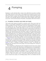
1.4.1—Sign
C1.4.1
Structural supports for signs include both overhead and
roadside sign structures that are intended to support highway
traffic signs and markers.
Typical overhead and roadside sign supports are shown
in Figure 1-1. Overhead sign structures are generally of the
bridge or cantilever type. It is also common to support signs
on existing grade separation structures that span the traffic
lanes.
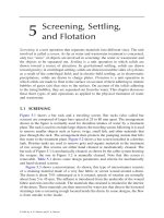
1.4.2—Luminaire
C1.4.2
Structural supports for luminaires include typical
lighting poles, pole top-mounted luminaire poles, and highlevel poles.
The lighting of modern freeways includes the use of
typical lighting poles, generally tubular pole shafts that
support one to two luminaires and range in height from about
9 m (30 ft) to 17 m (55 ft). High-level lighting poles are
normally in heights from about 17 m (55 ft) to 46 m (150 ft)
or more, usually supporting 4 to 12 luminaires; they are used
to illuminate large areas. Typical luminaire supports and
high-level supports are shown in Figure 1-2.
© 2009 by the American Association of State Highway and Transportation Officials. All rights reserved.
Duplication is a violation of applicable law.
1-4
STANDARD SPECIFICATIONS FOR STRUCTURAL SUPPORTS FOR HIGHWAY SIGNS, LUMINAIRES, AND TRAFFIC SIGNALS
Figure 1-1—Sign Supports
© 2009 by the American Association of State Highway and Transportation Officials. All rights reserved.
Duplication is a violation of applicable law.
SECTION 1: INTRODUCTION
Figure 1-2—Luminaire Structural Supports
© 2009 by the American Association of State Highway and Transportation Officials. All rights reserved.
Duplication is a violation of applicable law.
1-5
1-6
STANDARD SPECIFICATIONS FOR STRUCTURAL SUPPORTS FOR HIGHWAY SIGNS, LUMINAIRES, AND TRAFFIC SIGNALS
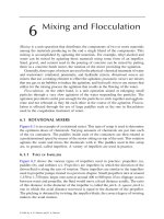
1.4.3—Traffic Signal
C1.4.3
Structural supports for mounting traffic signals include
pole top, cantilevered arms, bridge, and span wires.
Typical traffic signal supports are shown in Figure 1-3.
1.4.4—Combination Structures
C1.4.4
Combination structures include structural supports that
combine any of the functions described in Articles 1.4.1,
1.4.2, and 1.4.3.
Generally, combination structures are composed of a
luminaire support and a traffic signal support. Other
structures may combine traffic signal or luminaire supports
with those for utility lines.
© 2009 by the American Association of State Highway and Transportation Officials. All rights reserved.
Duplication is a violation of applicable law.
SECTION 1: INTRODUCTION
Figure 1-3—Traffic Signal Structural Supports
© 2009 by the American Association of State Highway and Transportation Officials. All rights reserved.
Duplication is a violation of applicable law.
1-7
1-8
STANDARD SPECIFICATIONS FOR STRUCTURAL SUPPORTS FOR HIGHWAY SIGNS, LUMINAIRES, AND TRAFFIC SIGNALS
1.5—REFERENCES
AASHTO. 1968. AASHTO Highway Definitions. American Association of State Highway and Transportation Officials,
Washington, DC.
AASHTO. 2001. Standard Specifications for Structural Supports for Highway Signs, Luminaires and Traffic Signals, Fourth
Edition, LTS-4. American Association of State Highway and Transportation Officials. Washington, DC.
AASHTO. 2002. AASHTO Standard Specifications for Highway Bridges, 17th Edition, HB-17. American Association of State
Highway and Transportation Officials, Washington, DC.
AASHTO. 2007. AASHTO LRFD Bridge Design Specifications, Fourth Edition, LRFDUS-4-M and LRFDSI-4. American
Association of State Highway and Transportation Officials, Washington, DC.
AASHTO. 2008. Standard Specifications for Transportation Materials and Methods of Sampling and Testing. 28th Edition,
HM-28. American Association of State Highway and Transportation Officials, Washington, DC.
ASTM. 2001. Book of ASTM Standards. American Society for Testing and Materials, West Conshohocken, PA.
Fouad, F. H., E. A. Calvert, and E. Nunez. 1998. Structural Supports for Highway Signs, Luminaires, and Traffic Signals,
NCHRP Report 411. Transportation Research Board, National Research Council, Washington, DC.
© 2009 by the American Association of State Highway and Transportation Officials. All rights reserved.
Duplication is a violation of applicable law.
SECTION 2: GENERAL FEATURES OF DESIGN
TABLE OF CONTENTS
2
2.1—SCOPE .............................................................................................................................................................................. 2-1
2.2—DEFINITIONS ................................................................................................................................................................. 2-1
2.3—AESTHETICS .................................................................................................................................................................. 2-2
2.4—FUNCTIONAL REQUIREMENTS................................................................................................................................ 2-2
2.4.1—Lighting Systems.................................................................................................................................................... 2-2
2.4.1.1—Vertical Heights for Luminaire Supports.................................................................................................... 2-2
2.4.1.2—Illumination of the Roadway....................................................................................................................... 2-3
2.4.2—Structural Supports for Signs and Traffic Signals................................................................................................. 2-3
2.4.2.1—Vertical Clearances...................................................................................................................................... 2-3
2.4.2.2—Size, Height, and Location of Signs............................................................................................................ 2-5
2.4.2.3—Illumination and Reflectorization of Signs................................................................................................. 2-5
2.4.2.4—Variable Message Signs .............................................................................................................................. 2-5
2.5—ROADSIDE REQUIREMENTS FOR STRUCTURAL SUPPORTS .......................................................................... 2-5
2.5.1—Clear Zone Distance............................................................................................................................................... 2-6
2.5.2—Breakaway Supports .............................................................................................................................................. 2-6
2.5.2.1—Foundations ................................................................................................................................................. 2-6
2.5.2.2—Impact Height .............................................................................................................................................. 2-6
2.5.3—Guardrails and Other Barriers................................................................................................................................ 2-7
2.5.4—Roadside Sign and Luminaire Supports ................................................................................................................ 2-7
2.5.5—Overhead Sign Supports and High-Level Lighting Supports ............................................................................... 2-7
2.5.6—Traffic Signal Supports .......................................................................................................................................... 2-7
2.5.7—Gores....................................................................................................................................................................... 2-7
2.5.8—Urban Areas............................................................................................................................................................ 2-8
2.5.9—Joint-Use Supports ................................................................................................................................................. 2-8
2.6—CORRELATION OF STRUCTURAL SUPPORT DESIGN WITH ROADWAY AND BRIDGE DESIGN ........... 2-8
2.6.1—Signs ....................................................................................................................................................................... 2-8
2.6.2—Luminaires.............................................................................................................................................................. 2-8
2.7—MAINTENANCE............................................................................................................................................................. 2-8
2.8—REFERENCES................................................................................................................................................................. 2-9
2-i
© 2009 by the American Association of State Highway and Transportation Officials. All rights reserved.
Duplication is a violation of applicable law.
SECTION 2:
GENERAL FEATURES OF DESIGN
2.1—SCOPE
C2.1
Minimum requirements are provided or referenced for
aesthetics, clearances, constructibility, inspectability, and
maintainability of structural supports. Guidelines for
determining vertical and lateral clearances, use of breakaway
supports, use of guardrails, illumination of the roadway, sizes
of signs, illumination and reflectorization of signs, and
maintenance are found in the following references:
This Section is intended to provide the Designer with
information and references to determine the configuration,
overall dimensions, and location of structural supports for
highway signs, luminaires, and traffic signals. The material in
this Section is broad in nature. No attempt has been made to
establish rigid criteria in such areas as vertical heights of traffic
signal and luminaire supports and levels of illumination. This
Section provides references and considerations for the
different aspects of design that should be considered in the
preliminary stages of a project. In addition to the requirements
provided within this Section, many Owners have their own
requirements.
•
A Policy on Geometric Design of Highways and Streets,
•
Manual on Uniform Traffic Control Devices,
•
Roadside Design Guide,
•
AASHTO Maintenance Manual for Roadways and
Bridges, and
•
Roadway Lighting Design Guide.
2.2—DEFINITIONS
Barrier—A longitudinal traffic barrier, usually rigid, used to shield roadside obstacles or nontraversable terrain features. It may
occasionally be used to protect pedestrians from vehicle traffic.
Breakaway—A design feature that allows a sign, luminaire, or pole top–mounted traffic signal support to yield, fracture, or
separate near ground level on impact.
Clear Zone—The total roadside border area, starting at the edge of the traveled way, available for unobstructed use by errant
vehicles.
Clearance—Horizontal or vertical dimension to an obstruction.
Curb—A vertical or sloping surface, generally along and defining the edge of a roadway or roadway shoulder.
Gore—The center area immediately past the point where two roadways divide at an acute angle, usually where a ramp leaves a
roadway.
Guardrail—A type of longitudinal traffic barrier, usually flexible.
Mounting Height—Minimum vertical distance to the bottom of a sign or traffic signal, or to the center of gravity of a luminaire,
relative to the pavement surface.
Pedestal Pole—A relatively short pole supporting a traffic signal head attached directly to the pole.
Roadside—The area between the shoulder edge and the right-of-way limits, or the area between roadways of a divided highway.
2-1
© 2009 by the American Association of State Highway and Transportation Officials. All rights reserved.
Duplication is a violation of applicable law.
2-2
STANDARD SPECIFICATIONS FOR STRUCTURAL SUPPORTS FOR HIGHWAY SIGNS, LUMINAIRES, AND TRAFFIC SIGNALS
2.3—AESTHETICS
C2.3
The structural support should complement its
surroundings, be graceful yet functional in form, and present
an appearance of adequate strength. The support should have a
pleasing appearance that is consistent with the aesthetic effect
of the highway’s other physical features. Supports should have
clean, simple lines, which will present minimum hazard to
motorists.
Structural supports should be designed and located so as
not to distract the motorist’s attention or obstruct the view of
the highway. Supports should be placed so they do not
obstruct the view of other signs or important roadway features.
The effect that signing or lighting installations have on the
surrounding environment should be evaluated.
The appearance of ordinary structural supports should
consider aesthetics and function. Combination poles, which
serve multiple functions for lighting, traffic control, and
electrical power, should be taken under consideration to reduce
the number of different poles along the highway.
2.4—FUNCTIONAL REQUIREMENTS
2.4.1—Lighting Systems
C2.4.1
General guidelines concerning lighting systems for
highways may be found in An Informational Guide for
Roadway Lighting.
The Designer should select the light source, luminaire
distribution, mounting height, and luminaire overhang based
on such factors as geometry and character of the roadway,
environment, proposed maintenance, economics, aesthetics,
and overall lighting objectives. Some communities limit the
amount of surrounding glare from illumination systems, and
shielding may be required. The same average level of lighting
can usually be obtained by more than one installation
arrangement. An Informational Guide for Roadway Lighting
provides information on level and uniformity of illuminance
and luminance, quality of light, location of poles, use of
breakaway devices, high-mast poles, and maintenance.
Additional information may also be found in A Study of
Roadway Lighting. Additional information on breakaway
devices for lighting poles may be found in the Roadside
Design Guide.
2.4.1.1—Vertical Heights for Luminaire Supports
The height of the luminaire support should be determined
by the Designer to fit the particular need and situation.
C2.4.1.1
Some items that should be considered by the Designer in
determining the height of a luminaire support are as follows:
•
Glare characteristics of the highway,
•
Desired level of illumination and distribution of light over
the roadway area,
•
Photometric characteristics of a selected lamp and
luminaire,
•
Available space for placing the supports, and
•
Maintenance capability (maximum attainable servicing
height).
Height restrictions may be imposed by various
government agencies, such as the Federal Highway
Administration (FHWA) with respect to breakaway devices
and the Federal Aviation Administration for aircraft
considerations.
© 2009 by the American Association of State Highway and Transportation Officials. All rights reserved.
Duplication is a violation of applicable law.
SECTION 2: GENERAL FEATURES OF DESIGN
2.4.1.2—Illumination of the Roadway
The Designer should consider the quality of light and the
level of illumination for a roadway lighting system.
2-3
C2.4.1.2
Highway illumination is provided to improve driver
nighttime visibility and to promote safer and more efficient use
of special roadway facilities located at ramps, intersections,
and potentially hazardous areas.
The amount of illumination that should be provided over a
roadway depends on the interaction among visibility, visual
comfort, light distribution, and the geometry of the lighting
system. Disability and discomfort glare, pavement glare, road
location, and obstructions to visibility and traffic patterns are
other factors that influence the level of illumination to be
provided by a lighting system.
A luminaire installation should provide a visual
environment that is conducive to safe and comfortable night
driving. Where pedestrian safety is not involved, there is no
indication that the lighting of bridges and overpasses should be
any different from elsewhere on the highway.
2.4.2—Structural Supports for Signs and Traffic Signals
2.4.2.1—Vertical Clearances
Overhead sign and overhead traffic signal structures shall
provide a vertical clearance over the entire width of the
pavement and shoulders of 300 mm (1 ft) greater than the
required minimum vertical clearance of overpass structures on
the route. The vertical clearance shall be either in conformance
with A Policy on Geometric Design of Highways and Streets
for the functional classification of the highway, or exceptions
thereto shall be justified. Possible reduction of vertical
clearance should be investigated. Additional guidance on
vertical clearances may be found in the Manual on Uniform
Traffic Control Devices.
C2.4.2.1
The minimum clearance should include an allowance for
possible future overlays.
The additional 300-mm (1-ft) vertical clearance is
required so that high vehicles will strike the stronger overpass
structures first, thereby lessening the chance of major
collision damage to the structurally weaker overhead sign
support or traffic signal support structures. A depiction of this
clearance limit is illustrated in Figure 2-1.
© 2009 by the American Association of State Highway and Transportation Officials. All rights reserved.
Duplication is a violation of applicable law.
2-4
STANDARD SPECIFICATIONS FOR STRUCTURAL SUPPORTS FOR HIGHWAY SIGNS, LUMINAIRES, AND TRAFFIC SIGNALS
Notes:
a
See Article 2.5.1 on Clear Zone Distances and Article 2.5.2 on Breakaway Supports
b
See Article 2.5.3 on Guardrails and Other Barriers
c
See Manual on Uniform Traffic Control Devices
Figure 2-1—Location of Structural Supports
© 2009 by the American Association of State Highway and Transportation Officials. All rights reserved.
Duplication is a violation of applicable law.
SECTION 2: GENERAL FEATURES OF DESIGN
2.4.2.2—Size, Height, and Location of Signs
The Manual on Uniform Traffic Control Devices should
be consulted for the sizes, heights, and placement of signs for
any installation.
2.4.2.3—Illumination and Reflectorization of Signs
Illumination and reflectorization of signs should conform
with the provisions of the Manual on Uniform Traffic Control
Devices.
Except where reflectorization is deemed adequate, all
overhead sign installations should normally be illuminated.
The lighting equipment should produce uniform illumination
for the sign surface and the position of the lighting fixtures
should not impair normal viewing of the sign or obstruct view
of the roadway. Where internal illumination is used in
conjunction with translucent materials, the colors of the sign
should appear essentially the same by night and day.
2.4.2.4—Variable Message Signs
2-5
C2.4.2.2
The Manual on Uniform Traffic Control Devices includes
information on signs for sizes, illumination and
reflectorization, location, height, and lateral clearance.
C2.4.2.3
An Informational Guide for Roadway Lighting provides
some information for luminance and illuminance of signs.
High-intensity reflectorized sheeting can be used to
eliminate the need for sign illumination and maintenance
walkways.
C2.4.2.4
Cantilevered support structures for variable message signs
(VMS) shall be designed for fatigue in accordance with
Section 11, “Fatigue Design.”
The design of VMS support structures, enclosures, and
connections to the support structure will normally require
additional considerations that are beyond the scope of these
Specifications.
VMS are composed of lamps or luminous elements that
may be visible during the day as well as at night. The lamps
and electronics are contained within an enclosure, which
weighs significantly more than most sign panels.
NCHRP Report 411 provides some information regarding
the design of VMS support structures. Additional design
considerations that are not provided in the report may still be
required.
2.5—ROADSIDE REQUIREMENTS FOR
STRUCTURAL SUPPORTS
C2.5
Consideration shall be given to safe passage of vehicles
adjacent to or under a structural support. The hazard to errant
vehicles within the clear zone distance, defined in Article
2.5.1, should be minimized by locating obstacles a safe
distance away from the travel lanes. Roadside requirements
and location of structural supports for highway signs,
luminaires, and traffic signals should generally adhere to the
principles given in Articles 2.5.1 through 2.5.9.
Where possible, a single support should be used for dual
purposes (e.g., signals and lighting). Consideration should also
be given to locating luminaire supports to minimize the
necessity of encroaching on the traveled way during routine
maintenance.
© 2009 by the American Association of State Highway and Transportation Officials. All rights reserved.
Duplication is a violation of applicable law.
2-6
STANDARD SPECIFICATIONS FOR STRUCTURAL SUPPORTS FOR HIGHWAY SIGNS, LUMINAIRES, AND TRAFFIC SIGNALS
2.5.1—Clear Zone Distance
C2.5.1
Structural supports should be located in conformance with
the clear zone concept as contained in Chapter 3, “Roadside
Topography and Drainage Features,” of the Roadside Design
Guide, or other clear zone policy accepted by the FHWA.
Where the practical limits of structure costs, type of structures,
volume and design speed of through-traffic, and structure
arrangement make conformance with the Roadside Design
Guide impractical, the structural support should be provided
with a breakaway device or protected by the use of a guardrail
or other barrier.
The clear zone, illustrated in Figure 2-1, is the roadside
border area beyond the traveled way, available for safe use by
errant vehicles. This area may consist of a shoulder, a
recoverable slope, a nonrecoverable slope, and/or a clear runout area. The desired width is dependent on the traffic volumes
and speeds and on the roadside geometry.
Suggested minimum clear zone distances are provided in
the Roadside Design Guide and are dependent on average
daily traffic, slope of roadside, and design vehicle speed.
Additional discussions of clear zone distances and lateral
placement of structural support may be found in the Manual
on Uniform Traffic Control Devices and A Policy on
Geometric Design of Highways and Streets.
2.5.2—Breakaway Supports
C2.5.2
Breakaway supports should be used for luminaire and
roadside sign supports when they cannot be placed outside the
roadside clear zone or behind a guardrail. The requirements of
Section 12, “Breakaway Supports,” shall be satisfied. The
requirements of Articles 2.5.2.1 and 2.5.2.2 should be met for
the proper performance of the breakaway support.
Breakaway supports housing electrical components shall
have the use of electrical disconnects considered for all new
installations and for existing installations that experience
frequent knockdown.
Generally, breakaway supports should be provided
whenever the support is exposed to traffic. Breakaway
supports cannot usually be incorporated with overhead sign
bridges, cantilever overhead signs, or high-level lighting
supports. These structure types can often be placed outside the
clear zone; however, if they are located within the clear zone,
barrier protection is required.
Article 12.5.3 contains information on electrical
disconnects.
2.5.2.1—Foundations
The top of foundations and projections of any rigidly
attached anchor bolts or anchor supports should not extend
above the ground level enough to increase the hazard or to
interfere with the operation of a breakaway support.
2.5.2.2—Impact Height
Breakaway supports should be located such that the
location of impact of an errant vehicle’s bumper is consistent
with the maximum bumper height used in breakaway
qualification tests.
C2.5.2.1
Foundations for breakaway supports located on slopes are
likely to require special details to avoid creating a notch in the
slope that could impede movement of the support when broken
away or a projection of the foundation that could snag the
undercarriage of an impacting vehicle. Foundations should be
designed considering the breakaway stub height limitations of
Article 12.5.3.
C2.5.2.2
The breakaway performance of most, if not all,
breakaway supports degrades with an increase in impact
height. Typically, the bumper center height in breakaway
qualification tests is about 450 mm (18 in.). Research suggests
that a breakaway support should not be located where the
trajectory of an errant vehicle is likely to result in the bumper
of the vehicle striking the support more than 700 mm (28 in.)
above the ground line at the support. This criterion will be met
where a foreslope is no greater than 1 to 6 or the face of the
support is not more than 600 mm (24 in.) outside the
intersection of a shoulder slope and a 1 to 4 foreslope.
© 2009 by the American Association of State Highway and Transportation Officials. All rights reserved.
Duplication is a violation of applicable law.
SECTION 2: GENERAL FEATURES OF DESIGN
2-7
2.5.3—Guardrails and Other Barriers
C2.5.3
The location of roadside sign and luminaire supports
behind a guardrail should provide clearance between the back
of the rail and the face of the support to ensure that the rail will
deflect properly when struck by a vehicle. Continuity of the
railing on rigid highway structures should not be interrupted
by sign or luminaire supports.
The clearance between the edge of a sign panel, which
could present a hazard if struck, and the back of a barrier
should also take into consideration the deflection of the rail.
The edge of a sign shall not extend inside the face of the
railing.
Guardrails, as illustrated in Figure 2-1, are provided to
shield motorists from fixed objects and to protect fixed objects,
such as overhead sign supports. The Roadside Design Guide
provides guidelines for the provision of roadside barriers for
fixed objects.
The clearance between the back of the barrier and the face
of the support may vary, depending on type of barrier system
used. The Roadside Design Guide may be used to determine
the proper clearance.
2.5.4—Roadside Sign and Luminaire Supports
C2.5.4
Roadside sign and typical luminaire supports, within the
clear zone distance specified in Article 2.5.1, should be
designed with a breakaway feature acceptable under NCHRP
Report 350, or protected with a guardrail or other barrier.
Where viewing conditions are favorable, roadside sign and
typical luminaire supports may be placed outside the clear
zone distance.
Where there is a probability of being struck by errant
vehicles, even supports outside this suggested clear zone
should preferably be breakaway.
2.5.5—Overhead Sign Supports and High-Level Lighting
Supports
C2.5.5
Overhead sign and high-level lighting structural supports
should be placed outside the clear zone distance; otherwise,
they should be protected with a proper guardrail or other
barrier.
Overhead sign and high-level lighting supports are
considered fixed-base support systems that do not yield or
break away on impact. The large mass of these support
systems and the potential safety consequences of the systems
falling to the ground necessitate a fixed-base design. Fixedbase systems are rigid obstacles and should not be used in the
clear zone area unless shielded by a barrier. In some cases, it
may be cost effective to place overhead sign supports outside
the clear zone with no barrier protection when the added cost
of the greater span structure is compared with the long-term
costs of guardrail and vegetation maintenance. Some structures
can sometimes be located in combination with traffic barriers
protecting other hazards, such as culverts, bridge ends, and
embankments.
2.5.6—Traffic Signal Supports
C2.5.6
Traffic signal supports that are installed on high-speed
facilities should be placed as far away from the roadway as
practical. Shielding these supports should be considered if they
are within the clear zone for that particular roadway.
Traffic signal structural supports with mast arms or span
wires normally are not provided with a breakaway device.
However, pedestal pole traffic signal supports are
appropriately designed to be breakaway. Pedestal poles should,
if possible, be placed on breakaway supports because they are
usually in close proximity to traffic lanes.
2.5.7—Gores
Where obstruction in the gore is unavoidable within the
clear zone, protection should be provided by an adequate crash
cushion or the structure should be provided with a breakaway
device.
© 2009 by the American Association of State Highway and Transportation Officials. All rights reserved.
Duplication is a violation of applicable law.