Classification and petrophysical characterisation of miocene carbonate reservoir in well RR02, Song Hong basin, Vietnam
Bạn đang xem bản rút gọn của tài liệu. Xem và tải ngay bản đầy đủ của tài liệu tại đây (817.83 KB, 8 trang )
PETROLEUM EXPLORATION & PRODUCTION
PETROVIETNAM JOURNAL
Volume 6/2020, pp. 22 - 29
ISSN 2615-9902
CLASSIFICATION AND PETROPHYSICAL CHARACTERISATION
OF MIOCENE CARBONATE RESERVOIR IN WELL RR02,
SONG HONG BASIN, VIETNAM
Ta Thi Hoa, Nguyen Hoang Anh
Vietnam Petroleum Institute (VPI)
Email:
Summary
This study performs an integrated method using thin section and well log data to determine rock fabrics and their relationship with
the rock pore system in Miocene carbonate reservoirs of well RR02, southern Song Hong basin, Vietnam. By thin section analysis, mineral
components and pore types of carbonate rocks were determined, creating a basis for carbonate classification and grouping samples
into different petrophysical classes. Zoning, identification of dominant changing trend of the petrographic composition and porosity
estimation were then conducted based on the combination of different standard log curves, including gamma ray (GR), photoelectric
factor (PEF), neutron porosity (NPHI), density (RHOB) and sonic (DT). Four types of rock fabrics were diagnosed along a nearly 90m-thick
carbonate reservoir, namely, grainstone, grain-dominated packstone, wackstone and boundstone. Two main pore types were found
corresponding to each identified carbonate fabric, including interparticle and vuggy pores estimated by well log interpretation in the
range of 5.9% to 10% and 2.9% to 21.5%, respectively. In well RR02, carbonate reservoir was mostly formed by limestone and could be
divided into 2 zones with the lower affected by dolomitisation proved by the results of petrographic analysis, log curve characteristics
and well log interpretation.
Key words: Carbonate reservoir, petrographic analysis, well log interpretation, porosity, dolomite.
1. Introduction
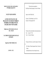
The study area is located about 80 km offshore
Vietnam in the southern part of the Song Hong basin
(Figure 1). The Miocene carbonate is an isolated platform,
established on the horst structural high throughout the
Early and Middle Miocene and ending in the Late Miocene
due to the development of siliciclastic sediment, affected
by regional uplift from the West. The estimated gas reserve
is about 4 TCF with approximately 30% CO2.
Petrophysical properties of carbonate reservoirs
are more difficult to be determined than those of
siliciclastic reservoirs because of their heterogeneity. The
carbonate pore network that controls the petrophysical
properties, such as porosity, permeability and saturation,
is distributed irregularly from well to basin scale and
Date of receipt: 26/3/2020. Date of review and editing: 27/3 - 6/5/2020.
Date of approval: 5/6/2020.
22
PETROVIETNAM - JOURNAL VOL 6/2020
classified into various classes, including interparticle and
vuggy porosity [2]. In order to classify carbonate rock
types and characterise their petrophysical properties,
core samples are necessary to be collected and
petrographic analysis using thin sections also needs to
be carried out. 17 thin section samples obtained from
Miocene carbonate reservoir of well RR02 were analysed
using petrophysical microscope at the Laboratory
Centre of the Vietnam Petroleum Institute (VPI-Labs).
The thin section analysis provides information on main
minerals, percentages of porosity, and rock fabric texture.
Classification of carbonate rocks and their pore types
were classified and compared using Folk’s, Dunham’s,
Choquette & Pray’s and Lucia’s classification charts [3 7]. Based on Lucia’s scheme [7], petrophysical class was
categorised for each sample corresponding to its fabric.
In addition, standard log curves were used for zoning
and well log interpretation, including GR (gamma ray),
RD (resistivity), NPHI (neutron), RHOB (bulk density), DTC
(sonic), and PEF (photoelectric factor). Different cross-
PETROVIETNAM
Hoang Sa
islands
Truong Sa
islands
Generalised stratigraphic column and location of studied area
(Christian J.Strohmenger; 2018)
JMJ I-MAP GIS Product Suite
Figure 1. Location map and general stratigraphic column of the study area [1].
Thin section analysis
Well log analysis
Identification and
quantification of
grains, minerals, matrix
Pore type
identification and
estimation
Zoning, mineral
identification
Total allochems,
calcite, dolomite,
matrix and others
Interparticle,
vuggy pores
Wireline, DGA- Uma &
RHOB-PEF cross plots
Classification of carbonate rock
[3, 5]
Petrophysical
interpretation
Total, interparticle,
vuggy porosity, S w
Classification of pore types
[6, 7]
Classification, petrophysical
characterisation of carbonate reservoir
Figure 2. Methodology for the study.
plots were also applied to determine the changing trend
of main mineral components versus depth, including
apparent matrix volumetric photoelectric factor (Uma) apparent matrix grain density (DGA) introduced by Burke
et al. [8, 9] and PEF vs RHOB proposed by Schlumberger
[10]. Uma and DGA are shown in Equation (1):
=
×
=
=
+ 0.1883
1.0704
−
×Ф
1−∅
−
1 −Ф
f
(1)
×Ф
PETROVIETNAM - JOURNAL VOL 6/2020
23
PETROLEUM EXPLORATION & PRODUCTION
Where:
PEF: Photoelectric factor (b/e);
фt: Total porosity (fraction);
RHOBf: Pore fluid density; 0.692 g/cc for gas interval
and 1.0 g/cc for water interval;
Uf: Pore fluid volumetric factor 0.398 (barns/cc);
cc).
Uma: Apparent matrix volumetric cross section (barns/
The well log interpretation was conducted to provide
detailed petrophysical information such as porosity,
water saturation and net pay along the wellbore (Figure
2). Density, neutron and alternative sonic methods were
used to estimate porosity while the gas effect was taken
into account by inputting gas density in related porosity
models. In carbonate rocks, the type representing
interparticle porosity [4] and vuggy porosity (фν) is
calculated by subtracting interparticle porosity (sonic
porosity) from total porosity (neutron - density porosity).
2. Results and discussion
Results from thin section analysis and well log
interpretation have been utilised to classify the rock
fabrics and characterise the petrophysical properties
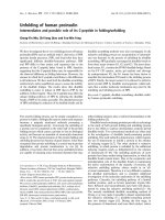
of this reservoir. Figure 3 shows that collected samples
considerably comprise carbonate allochems, sparry
cement and micrite. By thin section analysis, total porosity
Grainstone
Grain-dominated packstone dolomitic
Figure 3. Thin section analysis of RR02 samples.
24
PETROVIETNAM - JOURNAL VOL 6/2020
was estimated from good to excellent as ranging from
10% to 25.9% in total, in which pores were mostly
formed by separate vugs, interparticles, intercrystals
and touching vugs. Vuggy porosity was approximately
from 4% to 15.3%, formed by intraparticle, moldic pores
and dissolution of lime mud matrix and cement. Besides,
interparticle porosity, which is formed by the arrangement
of allochems and dissolution of previous micrite and
sparry cement filled among grains, varied from 0 to 17.3%.
Fracture pores were also locally noted with minor value
(Figure 4).
According to Folk [3], 7 rock samples were recognised
as bio-micrite and 9 samples were interpreted as unsorted
bio-sparite, in which 4 samples were dolomitised partly
with medium crystal size. There is only one thin section
determined as bio-lithite and it was also affected by
dolomitisation. Considering the textures named by
Dunham [5], 14 samples were interpreted as packstone
against one sample of grainstone and one of wackstone.
There is only one specimen recorded as boundstone
with characteristic of encrusted texture, in which red
algae and echinoderm were bound together during
deposition. The dolomitisation was also encountered in
5 samples at depths of 1794.25 m, 1798.75 m, 1804.75
m, 1814.51 m and 1814.77 m with dolomite crystal
size varying from 10.5 µm to 60 µm. Pore networks of
this well were classified based on Choquette & Pray’s
scheme [6]. There is a predominance of intraparticle
Grain-dominated packstone
Grain-dominated packstone
Boundstone dolomitic
Wackstone dolomitic
PETROVIETNAM
over interparticle and mold pore types. For the rocks
suffered from dolomitisation, intercrystal porosity was
also recorded. Besides, the processes such as solution,
cementation, and direction or stage (enlarged, reduced
or filled) of porosity evolution, were combined with
the pore size namely mesopore for rock description.
These terms were applied to classify the pore network
of 17 rock samples. Based on the classification of Lucia
[7], carbonate rocks could be divided into 2 groups:
Group I (grain-dominated fabric) includes 15 samples, in
which 14 samples are grain-dominated packstone and
one sample indicates grainstone fabric. Group II (muddominated fabric) consists of 2 samples with fabric of
wackstone and boundstone for each. Rocks affected by
dolomitisation were considered with dolomite crystal size
along with grain size. Rocks were then put into different
classes according to grain size, volumes of sparry calcite
and mud. There are 3 classes with 14 samples belonging
to Class 2, 1 sample to Class 1 and 2 others to Class 3.
Table 1 and Figure 5 display the comparison of different
carbonate classification schemes applied for carbonate
rocks of well RR02.
Three zones were divided corresponding to the well
log data of well RR02, in which the seal layer overlies on
Miocene carbonate layers. Zone 1 was defined with the
main lithology of shale based on the high value of GR (101
- 136 API), low value of RD from 1.7 Ohm.m to 3.8 Ohm.m,
PEF from 3.5 b/e to 5.6 b/e, DTC from 98 µs/ft to 130 µs/
ft, and N-D gap around 30 - 34%. The lithology of Zone 2
was diagnosed as limestone since GR is quite low from 23
API - 50 API, PEF from 5.0 b/e to 6.2 b/e, DTC from 57 µs/ft
to 85 µs/ft, N-D from 0% to 10%. Zone 3 was interpreted
as dolomitised limestone because of PEF values from 4.2
b/e to 5.5 b/e, and N-D ranging from 3% to 15%. The basic
rule to classify limestone and dolomitised limestone is the
overlay and separation of NPHI and RHOB log curves. In
Zone 2, these 2 logs overlie each other in contrast to their
separation in Zone 3 (Figure 6).
Cross-plots of RHOB versus PEF and Uma versus DGA
were applied to clarify lithology change for Zone 2 and
Zone 3. PEF vs RHOB cross-plot shows the predominance
of limestone with high value of porosity, varying from
5% to 25%. It is clear that using the raw curves as RHOB
and PEF indicates all the samples points belong to
the limestone lithology without neither dolomite nor
other lithology. In contrast, the Uma vs DGA cross-plot
demonstrates the general changing trend of main
minerals for Zone 2 as calcite with the concentration of
most data at calcite vertex while Zone 3 presents a part of
calcite that has been slightly affected by dolomitisation.
The porosity values derived by well log interpretation
(total porosity: 31.58%; interparticle: 10.04%; vug: 21.53%)
including both interparticle and vuggy porosity are much
higher than those of Zone 2 (total porosity: 18.79%;
interparticle: 5.88%; vug: 12.92%). The using of Uma vs
DGA cross-plot illustrates to be more effective approach
Percentage (%)
PETROGRAPHY ANALYSIS RESULT
Depth (m)
InterparƟcle
Secondary
Porosity
Porosity
7%
9%
Sparry Calcite
11%
Sparray
Dolomite
17%
Total
Allochem
49%
Micrite
Calcite
7%
*Total Allochems: Larger Benthic Foraminifera,Red Algae, Spongy,
Bryozoa, Pellet, Mollusk ,Coral, Ostracod, Bio-fragment
Orthochem: Micrite matrix, Sparray calcite, Sparry Dolomite
Figure 4. Result of thin section analysis, well RR02: Allochems with different shapes and sizes constitute a considerable proportion, ranging from 21.2% to 70% of total rock volume. The
components of allochems include larger benthic foraminifera, red algae, spongy, bryozoa, pellet, mollusk, echinoderm, coral, ostracod and unidentified bio-fragment. Sparry calcite was
present in large amount with significantly non-ferroan calcite from 3% to 38%, non-ferroan dolomite from 9.9% to 46.3%. Sparry cement was commonly found with morphologies of
isopachous to mosaic whereas dolomite was present as rhombic, euhedral to anhedral, fine to medium crystal size. Micrite matrix ranges from 2% to 20% and partly experienced a dolomitisation, converting lime mud matrix from subhedral to euhedral rhombic dolomite.
PETROVIETNAM - JOURNAL VOL 6/2020
25
Depth
1733.03
1733.5
1740.75
1744.03
1747.26
1748.5
1754.7
1758.5
1760.5
1763.73
1764.75
1768.73
1794.25
1798.75
1804.75
1814.51
1814.77
Sample No.
1
2
3
4
5
6
7
8
9
10
11
12
13
14
15
16
17
Folk [3]
PETROVIETNAM - JOURNAL VOL 6/2020
Dolomitised
Biomicrite
Dolomitised
Biolithite (1)
Dolomitised
Biosparite
Packed
Biomicrite
Unsorted
Biosparite(9)
Packed
Biomicrite
Packed
Biomicrite (7)
Unsorted
Biosparite
Dolomitised
Boundstone(1)
(red algae and
echinoderm)
Dolomitised
Packstone
Dolomitised
Wackstone(1)
Dolomitised
Packstone
Packstone
Grainstone (1)
Packstone (14)
Duham [5]
Fabric
Choquette & Pray [6]
Intercrystal pores
Intercrystal, intrapaticle pores
Intercrystal, cement-reduced
growth-framework
300 - 500
100 - 300
Wackstone(1)
>200
200 - 500
200 - 500
200 - 500
340 - 500
350 - 500
440 - 500
400 - 500
400 - 501
400 - 502
340 - 500
300 - 500
240 - 500
300 - 500
400 - 500
GDP Dolomitic
Boundstone
Dolomitic (1)
Intraparticle/Interparticle pores
Moldic, Intraparticle/Interparticle
pores
Solution enlargedFossil GDP(14)
Interparticle/Intraparticle pores
Moldic, Interparticle/Intraparticle
pores
Intrarparticle/Interparticle pores
Moldic, Intraparticle pores
Moldic, Intraparticle pores
Grainstone (1)
Intraparticle pores
Solution enlarged- Interparticle,
Interparticle, Intraparticle pores
Interparticle/Intraparticle pores
Fossil GDP
Solution enlargedIntraparticle/Interparticle pores
Moldic, Interparticle/Intraparticle
pores
Moldic, solution-enlarged
intraparticle,
GDP Dolomitic
intraparticle pores
Intraparticle pores
Classification of Pore types
Lucia [7]
Grain size/Crystal
size (µm)
Classification of Carbonate Rocks
Class 3
Class 2
Class 3
Class 2
Class 1
Class 2
Petrophysical
Class
26
Interparticle
17.3
10.3
7.9
3
3.7
2
5
4.3
Tr
4.7
17
5.3
14
Tr
3
4.7
11
2
0.3
0.3
0.3
0.3
0.3
0.3
9.7
15
4.7
Separated-Vug
7.3
8.3
7
10
10.6
8
11.7
2.3
15.3
9
4
11
5.7
15.3
Porosity
Fracture
Table 1. Comparison of carbonate classification using different schemes
Touching Vug
3
7
PETROLEUM EXPLORATION & PRODUCTION
PETROVIETNAM
Duham [5]
Folk [3]
Dolomitised
Boundstone
1
Dolomitised Biolithite
1
Dolomitised
Packed
Biomicrite
Biomicrite
2
Dolomitised
5
Biosparite
2
Unsorted
Biosparite
7
Dolomitised
Wackstone
1
Dolomitised
Packstone
3
Packstone
12
Lucia [7]
Rock fabric
Pore type
Bounstone, 1
Wackstone,1
Grainstone,1
Grain-Dominated Packstone, 14
Touching Vug
5%
Petrophysical class
Class 3, 2
Interparticle
7.55%
Separated-Vug
9.12%
Fracture
0.54%
Class 1,1
Class 2,14
Figure 5. Summary of carbonate classification by different methods.
RHOB(g/cc)
Zone_2
Zone_3
1700
Anhydrite
PEF(b/e)
1750
Zone_2
Zone_3
Quartz
DGA
Calcite
%Quartz
1800
Dolomite
•
Three zones are defined, zone 1 characterized by shale
•
Lower part of zone_3 is partly dolomiƟzed following Cross -Plots
%Dolomite
Heavy Minerals
Uma(barns/cc)
Figure 6. Zoning and identifying the changing trend of lithology composition based on well log.
to classify the general changing trend of limestone and
dolomite than the PEF-RHOB cross-plot, which has been
verified by results of both petrography analysis and well
log interpretation.
The well log interpretation results in Zone 2 with
38.9 m net pay, 21.4% effective porosity and 15.3% water
saturation and in Zone 3 with 28.3 m net pay, 29.1%
effective porosity and 27.8% water saturation. Gas water
contact (GWC) is interpreted as 1807 mMD as Figure 7.
The maximum flooding surface (MFS) is interpreted
at 1,772 mMD as the highest gamma curve marking
the transition of relative sea level from transgression
to regression (Figure 7). This could be linked with the
reactivation of strike-slip activities of Song Hong fault in
the Late Miocene. The lower part of MFS is interpreted
as deep marine environment in transgressive system
tract (TST) with a high rate of carbonate production
characterised by abundant red algae and larger benthic
PETROVIETNAM - JOURNAL VOL 6/2020
27
PETROLEUM EXPLORATION & PRODUCTION
foraminifera. This part includes thick carbonate with
higher poroperm properties compared to thinner
carbonate layers interbedded with carbonate cement
layers (2 - 3 m) above MFS. The upper part of MFS
deposits in a high stand system tract (HST) which is
bounded by MFS and sequence boundary (SB) as top
of Zone 2 in shallow water depth with upward stacking
patterns. The extensive porosity destructive characterised
by interbedded low-poroperm layers resulted from
significant marine cementation in HST period. The lower
effective porosity in Zone 2 compared with that of Zone
3 from core analysis and well log interpretation supports
the above interpretation. Top of Zone 2 is marked by
about 3 m of tight carbonate layer formed when the
carbonate was exposed as karst surfaces and reservoir
has been filled by carbonate cement through by meteoric
water realm. The thick shale zone above carbonate
formation illustrates the transition from shallow to deep
marine environment. Results of the petrography analysis
and well log response represent small fracture occurrence
with main interparticle porosity and secondary porosity
as vugs which suggests less tectonic activities affected on
this carbonate formation.
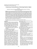
Figure 6 shows all integrating results from all
pertinent data of well RR02. As the petrographic analysis,
the dissolution of allochems and precipitation of calcite
cements are the main diagenesis processes recorded from
RR02 samples. The effective porosity is well matching with
the core porosity in track 7 with higher porosity in Zone
3. The increasing trend of dolomite content occurred
below the depth of 1,770 mMD (light blue fill in track 4),
which is consistent with the higher secondary porosity
resulting from well log interpretation (yellow fill in track 8).
Secondary porosity derived from well log interpretation
is always higher than those estimated from thin section
analysis. The reason could be the well log method reflects
the response of the whole pore space in their investigation
depth, whereas the thin section just provides information
of two dimensions rock slab within a small area.
As above-mentioned, the dolomite distribution
mostly observed in Zone 3 by integrating both thin
section analysis and Uma vs DGA cross-plot. The question
needs to be answered is why dolomite occurrence
only has an increasing tendency towards the lower
interval and whether it is correlated with petrophysical
properties in RR02. It could be explained that high CO2
content, confirmed by the testing result, is diffused from
the hydrocarbon reservoirs down into water bearing
zone resulting in the secondary leaching in Zone 3. The
diffusion process therefore causes dissolution of the fossil
assemblage, mainly made by red algae and larger benthic
foraminifers, to enrich the environment with Mg-calcite
which partly provoked the dolomitisation proved by
petrography analysis and well log interpretation results.
This result also explains why the dolomite component
was less observed in the above interval than in Zone 2,
where less red algae and LBF were found, and which is
located quite far from the water contact with multiple
•
DissoluƟon of allochems
and precipitaƟon of calcite
cements are main diagenesis
processes
•
CO2 diffusion from the
hydrocarbon reservoir down
into water zone (secondary
leaching)
•
DissoluƟon of fossil
assemblage (Red algae& large
benthic foraminifers) to
enrich in Mg-calcite
environment, causing partly
dolomiƟsaƟon process
Thin SecƟon
Image
1750
Dolomite
Partly-DolomiƟzed
1775
1800
Figure 7. Well log interpretation result in RR02.
28
PETROVIETNAM - JOURNAL VOL 6/2020
Ca2+,CO32 Mg2+
DolomiƟsaƟon
GWC
Water zone
GWC
PETROVIETNAM
barrier carbonate cement layers. Most of dolomite crystals
in the lower part of Zone 3 observed from thin section
analysis are euhedral (planar-e) in eogenesis process and
play a significant role to enhance reservoir properties in
well RR02. Details of zone division, log response values
and dolomitisation process are displayed and summarised
in Figure 7.
in petroleum resource estimation", SPE Reservoir Evaluation
& Engineering, Vol. 14, No. 1, pp. 25 - 34, 2011. DOI:
10.2118/142819-PA.
3. Conclusions
[4] F.J.Lucia, "Petrophysical parameters estimated
from visual descriptions of carbonate rocks: A field
classification of carbonate pore space", Journal of
Petroleum Technology, Vol. 35, No. 3, pp. 629 - 637, 1983.
DOI: 10.2118/10073-PA.
Miocene carbonate reservoirs, less experienced
tectonic activities, were formed by grain-dominated fabric,
including grain-dominated packstone and grainstone
with mainly allochem, sparry calcite, sparry dolomite and
micrite matrix. Petrography analysis and useful Uma - DGA
cross-plot are utilised to efficiently determine the general
changing trend of the lithology composition in carbonate
successions. Porosity estimated by well log interpretation
in well RR02 is from high to excellent, 2 - 38% (avg
20%), with diverse pore types. Secondary porosity by
cementation, micritisation, acidification, dissolution and
acidification processes is up to 19% (avg 8%). Secondary
leaching of the Mg-rich red algae and LBFs caused by
CO2 diffusion from the hydrocarbon reservoir down into
the water bearing zone could be the key factor for the
dolomitisation process occurring in the lower part. The
integrated method used in this research proves a significant
result on carbonate reservoir characterisation and it can
be applied for other wells in this carbonate field for a
better support to the above statement. Full assessment of
petrophysical properties of rock in consideration of other
parameters including permeability and related reservoir
behaviour parameters needs to be carried out to have an
insight about this heterogeneity reservoir.
References
[1] Christian J.Strohmenger, Lori Meyer, David
S.Walley, Mazlina Md Yusoff, Donald Y.Lyons, Jacqueline
Sutton, John M.Rivers, Beata von Schnurbein, and Nguyen
Xuan Phong, "Reservoir characterisation of the Middle
Miocene Ca Voi Xanh isolated carbonate platform",
Petrovietnam Journal, Vol. 6, pp. 10 - 24, 2018.
[3] Robert L.Folk, “Spectral subdivision of limestone
types”, Classification of carbonate rocks - A symposium,
AAPG Memoir, Vol. 1, pp. 62 - 84, 1962. DOI: 10.1306/
M1357.
[5] Robert J.Dunham, “Classification of carbonate
rocks according to depositional texture”, Classification
of carbonate rocks - A symposium, AAPG Memoir, Vol. 1,
pp. 108 - 121, 1962. DOI: 10.1306/M1357.
[6] Philip W.Choquette and Lloyd Charles Pray,
"Geologic nomenclature and classification of porosity
in sedimentary carbonate", AAPG Bulletin, Vol. 54, No. 2,
pp. 207 - 250, 1970.
[7] F.Jerry
Lucia,
"Rock-fabric/petrophysical
classification of carbonate pore space for reservoir
characterization", AAPG Bulletin, Vol. 79, No. 9, pp. 1275
- 1300, 1995. DOI: 10.1306/7834D4A4-1721-11D78645000102C1865D.
[8] J.A.Burke, R.L.Campbell, and A.W.Schmidt, “The
litho-porosity cross plot - A method of determining rock
characteristics for computation of log data”, SPE Illinois
Basin Regional Meeting, Evansville, Indiana, 30 - 31 October,
1969.
[9] Robert Cluff, Suzanne Cluff, Ryan Sharma, and
Chris Sutton, “A deterministic lithology model for the
green river-upper wasatch interval of the Uinta basin”,
AAPG Annual Convention & Exhibition 2015, Denver,
Colorado, 31 May - 3 June, 2015.
[10] Schlumberger, Log interpretation. Principles/
Applications. Texas: 1989.
[2] Vivian K.Bust, Joshua U.Oletu, and Paul
F.Worthington, "The challenges for carbonate petrophysics
PETROVIETNAM - JOURNAL VOL 6/2020
29