Optimising the under-reamer string design for wells at Hai Thach field, Nam Con Son basin
Bạn đang xem bản rút gọn của tài liệu. Xem và tải ngay bản đầy đủ của tài liệu tại đây (996.83 KB, 8 trang )
PETROVIETNAM
PETROVIETNAM JOURNAL
Volume 6/2020, pp. 37 - 44
ISSN 2615-9902
OPTIMISING THE UNDER-REAMER STRING DESIGN FOR WELLS
AT HAI THACH FIELD, NAM CON SON BASIN
Hoang Thanh Tung1, Nguyen Pham Huy Cuong2, Tran Hong Nam3, Le Quang Duyen4, Dao Thi Uyen4
1
Petrovietnam Drilling and Well Services Corporation (PV Drilling)
2
Bien Dong Petroleum Operating Company (Bien Dong POC)
3
Petrovietnam Exploration Production Corporation (PVEP)
4
Hanoi University of Mining and Geology (HUMG)
Email:
Summary
According to the drilling program approved for Hai Thach field, the drilling section below the 16” casing liner (14.85” internal
diameter) will be carried out by two separate BHAs: first drilling the 12.25” section by PDC bit to the section target, then under-reaming
the wellbore to 14.5” and 16.5” diameter in order to run 13.625” casing string. Using two separate BHAs for reaming the wellbore certainly
leads to a time increase in the run in hole (RIH) and pull out of the hole (POOH) of the drill-string and hence the associated costs such as
rig and other related third party services. Therefore, it is necessary to study and calculate the optimal drill-string design to ensure the
wellbore under-reaming as well as to minimise the drill-string running time, thereby improving the Drillex and Capex. The application
of the optimised reamer string design in the wells of Hai Thach field has brought a feasible concept that can be applied for other wells
having similar profiles and geological stratigraphy in Vietnam in the future.
Key words: Under-reamer string optimisation, wellbore reaming, drill-string simulation, reamer string design, Hai Thach field.
1. General
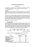
Well HT-xx is designed with a well profile completed
by a 30” conductor pipe and 22” surface casing × 16” casing liner × 13.625” intermediate casing × 10” intermediate
casing and 5.5” production tubing (Table 1).
According to the well design, the 16.5” hole section
is used for 13.625” casing running, the wellbore diameter
must reach 16.5” to ensure sufficient annular for cementing to achieve the highest quality and efficiency.
But the fact is that the 16” casing liner has internal diameter of only 14.85”. It is, therefore, merely possible to
drill inside casing with a bit of 14.5” when going through
cement below the 16” casing shoe and then reaming the
hole up to 16.5”; however, the 14.5” PDC bit cannot bring
up the borehole diameter up to 16.5” for 13.625” casing
running and cementing. So, the under-reaming equipment is needed to achieve the required wellbore diameter of 16.5” for running the 13.625” intermediate casing
(Figure 1).
Date of receipt: 14/6/2018. Date of review and editing: 14 - 28/6/2018.
Date of approval: 5/6/2020.
Because the 14.5” PDC bit was not available in the
market at the time of drilling operation, it required more
time as well as higher cost to order due to the customised
design and manufacture. Therefore, the solution in this
situation was to use a pilot drill-string with the 12.25” PDC
bit for reaming the borehole below 16” casing shoe to the
two diameters of 14.5” and 16.5” to reach the target mentioned above.
2. Optimal solution design
2.1. Primarily approved design
With the approved drilling program as described
above, for reaming the wellbore to 16.5” for the 13.625”
casing section, it is necessary to have two BHAs with details as follows (Tables 2 and 3).
- 12.25” pilot BHA, and
- 12.25” × 14.5” × 16.5” under-reaming BHA.
With pilot under-reaming BHAs, the drilling operation
needs to run the process at least twice. It includes making up 12.25” pilot BHA then drilling to section target and
POOH for 12.25” × 14.5” × 16.5” under-reaming BHA and
PETROVIETNAM - JOURNAL VOL 6/2020
37
PETROLEUM EXPLORATION & PRODUCTION
Table 1. Casing specification for well HT-xx [1]
Description
30” Conductor
22” Surface casing
16” Intermediate casing
13.625” Intermediate casing
10.75” × 10” Production casing
7.625” Contingency liner
5.5” Production liner
5.5” Production tubing
Grade
Weight
(lb/ft)
OD
(in)
ID
(in)
X56
X80
P110
Q125
SM125S
SM125S
P110
SM13CRS-110
SM13CRS-110
456
224
96
88.2
73.2
68.7
39.0
29.7
23.0
30
22
16
13.625
10.75
10
7.625
5.5
5.5
27
20
14.85
12.375
9.394
8.672
6.625
4.376
4.67
Inner
pressure
(psi)
4,900
6,360
6,920
10,030
13,670
15,050
12,620
19,670
14,530
Outer
pressure
(psi)
4,090
3,870
2,340
4,800
10,810
13,370
11,080
20,180
14,540
Yield
strength
(×1000 lbs)
7,521
5,278
3,065
3,191
2,660
2,516
1,231
959
729
- Calculate, run the simulation to
ensure that the drilling-string tools work
stable for the formation to be drilled,
30” Conductor pipe
Hammering
30” Conductor @320 m TVD
26” Hole section
#1: 26" BHA (Motor /MWD) drill vertical to Section
TD 1347.0mTVD /1348.0 mMD; WBM, KCL /PHPA
9.2~9.5 ppg MW
20” Surface casing @ +/- 1,341.5 m TVD
18.125” Hole section
Kick - off & Build & turn right section
#1. 18.125" Hole BHA (RSS/MWD/LWD/DH
Dynamic), KOP 1,458 mMD, 1.8º/30m BUR,
Complete build/turn to Max. 32.0º
Inclination/5.5º
Azimuth to section TD SBM 10.5 - 12.5 ppg MW
[Normal Barite]
13.625” x 16”
Swell Packer
16” Intermediate Casing @ +/- 1,341.5 m TVD
12.25” x 16.5” Hole Section
Hold & Tangent Section [32.0º Inclination / 5.5º
Azimuth]
10.75” x 10”
Casing Tie Back
#1. 12.25" Pilot BHA (RSS/MWD/LWD/DH
Dynamic) to section TD.
#2. 12.25" x 14.1/2" x 16.1/2" Under Reamer BHA
to section TD; SBM 14.5 - 15.9 ppg MW [Normal
Barite]
13.625” Intermediate Casing @ +/-2,870 m TVD
12.25” Hole Section
Hold & Tangent Section [32.0º Inclination / 5.5º
Azimuth]
#1. 12.25" BHA (RSS/MWD/LWD/DH Dynamic) to
section TD; SBM 17.3 ppg MW [Fine Grind Barite]
10” Intermediate casing @ +/-3,356 m TVD
8.5” Hole Section
Hold & Tangent Section [32.0º Inclination / 5.5º
Azimuth]
7.625” Contingency liner @ +/-3,500 m TVD
#1. 8.5” BHA (RSS/MWD/LWD/DH Dynamic)
to well TD; SBM 17.2 - 17.3 ppg MW [Fine Grind
Barite]
5.5” Production Tubing @ +/-3,816 m TVD
Figure 1. Well HT-xx profile.
reaming the borehole up to 16.5” as required for 13.625” casing running
and cementing. Undoubtedly, this process takes more time for POOH and
RIH, which obviously pumps up the costs related to rig waiting and third
parties services. Therefore, having an integrated solution to reduce the
cost but ensure the quality and efficiency of well construction is crucial.
2.2. Optimal solution proposal
To propose an optimal solution for BHA drilling and reaming, it is requisite to consider the following:
38
PETROVIETNAM - JOURNAL VOL 6/2020
- Review hole cleaning efficiency
and hydraulic model, simulate drilling
parameters to select the BHA design for
the highest ROP,
- Review the influence of directional
drilling equipment in the process with the
proposed BHA,
- Check the change of well trajectory
during drilling and reaming operation.
It is a must to consider all key elements and factors of well design, drilling
equipment, drill bit, geological features,
well trajectory, drilling fluids, drilling hydraulics, drilling parameters as well as other related factors. The results of the engineering study shown that during drilling
and reaming, the proposal for BHA drilling
and reaming from 12.25” to 14.5” diameter by SHO - Staged Smiths Hole Opener
(Figure 2) and 16.5” Rhino Reamer with an
integrated BHA (with 3 different cutting
inserts including drill, ream the borehole
by Rhino Reamer up to 16.5"). "The Rhino
Reamer XC gets around the limitations of
the existing reaming equipment from another manufacturer and offers some outstanding features such as full activation
with hydraulic mechanism or acceptance
of multiple open/close times during operation (Figure 3).
Rhino reamer XC has been put into operation worldwide since September 2012
PETROVIETNAM
Table 2. 12.25” pilot BHA configuration [2]
No.
Description
Outer
diameter
(in)
OD
(in)
Lower
Upper
connection connection
Accu.
length
(m)
Bit - PDC - fixed cutter
2
AutoTrak steering unit
3
Lower flex stabiliser
12.125
4
OnTrak II - MWD sensor sub
11.75
9.500
2.875
9.5 T2
9.5 T2
7.010
13.57
5
BCPM - MWD power and pulser sub
9.500
2.880
9.5 T2
9.5 T2
3.600
17.17
6
CoPilot
9.500
2.813
9.5 T2
9.5 T2
2.300
19.47
7
Top stop sub NM
9.500
2.813
9.5 T2
7.625 Reg
1.100
20.57
8
Sub - filter
9.500
2.813
7.625 Reg
7.625 Reg
1.700
22.27
9
Float sub (non-ported plunger)
String Stabiliser
11
Nozzle 5x20
Length
(m)
1
10
12.25
ID
(in)
6.625 Reg
0.400
11.860
2.480
6.625 Reg
9.5 T2
2.530
0.40
2.93
9.500
2.813
9.5 T2
9.5 T2
3.630
6.56
9.500
2.813
7.625 Reg
7.625 Reg
1.700
9.500
2.813
7.625 Reg
7.625 Reg
1.700
23.97
25.67
Sub - X/O
8.000
2.813
7.625 Reg
6.625 Reg
1.000
26.67
12
Drill collar x 6
8.125
2.813
6.625 Reg
6.625 Reg
56.40
83.07
13
Jar
8.000
2.813
6.625 Reg
6.625 Reg
9.500
92.57
14
Drill collar x 3
8.250
2.813
6.625 Reg
6.625 Reg
28.20
120.77
15
Accelerator
8.000
2.813
6.625 Reg
6.625 Reg
9.500
130.27
16
Drill collar x 1
8.250
2.813
6.625 Reg
6.625 Reg
9.400
139.67
17
Sub - X/O
8.000
2.813
6.625 Reg
VX54
1.000
140.67
18
5.5” HWDP ×16
5.500
4.000
VX54
VX54
152.00
292.67
19
5.5” DP
5.500
4.778
VX54
VX54
2774.03
3066.7
11.375
Table 3. 12.25”x14.5”x16.5” under-reaming BHA [2]
No.
Description
Outer
diameter
(in)
ID
(in)
6.625 Reg
0.40
0.40
8.000
2.813
6.625 Reg
6.625 Reg
1.70
2.10
8.000
2.813
6.625 Reg
6.625 Reg
1.70
3.80
Lower
Upper
connection connection
Length
(m)
Accu.
length
(m)
OD
(in)
1
Bullnose
8.000
2
String stabiliser
12.250
3
Float sub (non-ported plunger type)
4
Bit-hole opener (SHO)
14.500
8.000
3.000
6.625 Reg
7.625 Reg
4.00
7.80
5
Under reamer
16.500
9.500
2.700
7.625 Reg
7.625 Reg
4.50
12.30
6
Drill collar
9.500
2.813
7.625 Reg
7.625 Reg
9.40
21.70
7
Float sub (non-ported plunger type)
9.500
2.813
7.625 Reg
7.625 Reg
1.70
23.40
8
String stabiliser
9.500
2.813
7.625 Reg
7.625 Reg
2.00
25.40
12.250
9
Sub - X/O
8.000
2.813
7.625 Reg
6.625 Reg
1.00
26.40
10
Drill collar x 6
8.125
2.813
6.625 Reg
6.625 Reg
56.40
82.80
11
Jar
8.000
2.813
6.625 Reg
6.625 Reg
9.50
92.30
12
Drill collar x 3
8.250
2.813
6.625 Reg
6.625 Reg
28.20
120.50
13
Accelerator
8.000
2.813
6.625 Reg
6.625 Reg
9.50
130.00
14
Drill collar x 1
8.250
2.813
6.625 Reg
6.625 Reg
9.40
139.40
15
Sub - X/O
8.000
2.813
6.625 Reg
VX54
1.00
140.40
16
5.5” HWDP x16
5.500
4.000
VX54
VX54
152.00
292.40
17
5.5” DP
5.500
4.778
VX54
VX54
2772.60
3065.00
and some oil operators have successfully combined well
drilling and reaming but no one has applied the method
with 3 integrated cutting stages. Especially, this BHA proposal has never been applied for HPHT wells not only in
Vietnam but also all over the world so far. Some limitations of the optimised design are the equipment capability to ream up borehole and hole cleaning, and monitor
the well trajectory, namely:
PETROVIETNAM - JOURNAL VOL 6/2020
39
PETROLEUM EXPLORATION & PRODUCTION
Figure 2. Staged hole opener - SHO of Smiths Bit [3].
- Existing wellbore diameter
expansion
equipment
uses
a
combination
of
mechanical
mechanisms (ball-drop) to activate
the cutter block and retains only
one hydraulic mechanism during
operation. Since this combination
can be used only for a single opening
and closing cycle of cutting blades,
it reduces the equipment flexibility
during the reaming. This also makes it
difficult to drill a well through complex
geologic formations and the design
will greatly lower the hole cleaning
efficiency during and after drilling.
- Normally being activated by a
ball-drop mechanism, reamer is only
located above the MWD tools and
cannot be placed close to the drill
bit. This fact leads to the bare hole
increase below the borehole reaming
section. The length of borehole to be
expanded leads to an extreme risk for
the casing seat point in the abnormal
or high pressure as we need to place
the casing seat on the strongest and
most stable foundation possible to
guarantee the drilling to the next well
section.
- The incompatibility between
the cutting mechanisms of the
equipment leads to decrease ROP and
extend the drilling time.
2.3. Engineering study result
Simulation is run for proposed optimal BHA options and engineering/
design study as specified in Table 4.
The proposed drilling tool specifications are brought into calculation/
simulation and check for stability
through different types of formation.
The output is indicated in Table 4.
Figure 3. Rhino reamer XC [4].
40
PETROVIETNAM - JOURNAL VOL 6/2020
The bending stress for BHA is
checked with drilling parameter input
relevant to the types of drilled formation (Figure 5).
PETROVIETNAM
Table 4. The proposed BHA options
Option # 1
BHA 2
5,5" DP
5,5" HWDP x16
Sub - X/O
Drill collar x 1
Accelerator
Drill collar x 3
Jar
Drill collar x 6
Sub - X/O
Float sub (non ported
plunger type)
Sub filter
String stabilizer
Top stop sub NM
Co-pilot
BCPM-MWD power
and pulse sub
Ontrack II – MWD
sensor sub
Rhino reamer
SHO
Bit
Option # 2
Max.
OD
(in)
6.7500
7.0000
8.2500
8.2500
8.0000
8.2500
8.0625
8.1250
9.5000
9.5000
Accum.
Length
(ft)
9050.00
974.714
476.026
472.746
441.746
410.578
318.058
284.571
99.531
96.251
9.5000
12.250
9.5000
9.5000
9.5000
90.674
85.097
79.003
75.395
67.850
11.750
56.039
16.500
14.500
12.250
33.039
13.529
0.8990
BHA 2a
5,5" DP
5,5" HW DP x16
Sub - X/O
Drill collar x 1
Accelerator
Drill collar x 3
Jar
Drill collar x 6
Sub - X/O
Float sub (non ported
plunger type)
Sub filter
String stabilizer
Top stop sub NM
Co-pilot
BCPM-MWD power
and pulse sub
Ontrack II – MWD
sensor sub
Sub X/O
Rhino reamer
SHO
Bit sub
Bit
Option # 3
Max.
OD
(in)
6.7500
7.0000
8.2500
8.2500
8.0000
8.2500
8.0625
8.1250
9.5000
9.5000
Accum.
Length
(ft)
9050.00
979.927
481.239
477.959
446.959
415.791
323.271
289.784
104.744
101.464
9.5000
12.250
9.5000
9.5000
9.5000
95.887
90.310
87.030
83.422
75.877
11.750
64.394
9.500
16.500
14.500
8.0000
12.250
41.404
38.124
18.614
5.4910
0.8990
BHA 2b
5,5" DP
5,5" HWDP x16
Sub - X/O
Drill collar x 1
Accelerator
Drill collar x 3
Jar
Drill collar x 6
Sub - X/O
Float sub (non ported
plunger type)
Sub Filter
String stabilizer
Top stop sub NM
Co-pilot
BCPM-MWD power
and pulse sub
Ontrack II – MWD
sensor sub
Sub X/O
Rhino reamer
String stabilizer
Sub X/O
SHO
Bit sub
Bit
Option # 4
Max.
OD
(in)
6.7500
7.0000
8.2500
8.2500
8.0000
8.2500
8.0625
8.1250
9.5000
9.5000
Accum.
Length
(ft)
9050.00
986.487
487.799
484.519
453.519
422.351
329.831
296.344
111.304
108.024
9.5000
12.250
9.5000
9.5000
9.5000
102.447
96.870
93.590
89.982
82.437
11.750
70.954
9.500
16.500
14.250
8.0000
14.500
8.0000
12.250
47.964
44.684
25.174
21.894
18.614
5.4910
0.8990
BHA 2c
5 1/2" DP
5 1/2" HWDP x16
Sub - X/O
Drill collar x 1
Accelerator
Drill collar x 3
Jar
Drill collar x 6
Sub - X/O
Float sub (non ported
plunger type)
Sub filter
String stabilizer
Top stop sub NM
Co-pilot
BCPM-MWD power
and pulse sub
Ontrack II – MWD
sensor sub
Sub X/O
Rhino reamer
Sub X/O
String stabilizer
Sub X/O
SHO
Bit sub
Bit
Max.
OD
(in)
6.7500
7.0000
8.2500
8.2500
8.0000
8.2500
8.0625
8.1250
9.5000
9.5000
Accum.
Length
(ft)
9050.00
989.767
491.079
487.799
456.799
425.631
333.111
299.624
114.584
111.304
9.5000
12.250
9.5000
9.5000
9.5000
105.727
100.150
96.870
93.262
85.717
11.750
74.234
9.500
16.500
9.5000
14.250
8.0000
14.500
8.0000
12.250
51.244
47.694
28.454
25.174
21.894
18.614
5.4910
0.8990
Figure 4. Results of stability calculation of the integrated BHA when drilling and reaming through sandstone and shale formations.
Figure 5. Simulation results with parameter input corresponding to the integrated drilling and reaming BHA through sandstone.
PETROVIETNAM - JOURNAL VOL 6/2020
41
PETROLEUM EXPLORATION & PRODUCTION
Figure 6. The simulation results show the influence of directional drilling equipment to the proposed integrated BHA.
The simulation shows the influence
of directional drilling equipment to the
proposed integrated BHA.
Simulation of well geometry/trajectory changes and hydraulic model per
integrated BHA option and selection of
cutting blades shape for 3 cutting stage
mechanisms is shown in Figure 7.
The results of the well trajectory
change simulation during drilling and
reaming are shown in Figure 8.
42
PETROVIETNAM - JOURNAL VOL 6/2020
Figure 7. Simulation of the well geometry change during drilling and reaming.
PETROVIETNAM
Figure 8. Simulation of the well trajectory change during drilling and reaming.
Figure 9. Cutting shape/blades of drill bit, Stage Hole Opener and Rhino Reamer.
After engineering study in turn with the BHA proposed options (Figure 10), the selection of suitable integrated BHA for the drilling and reaming and with
the optimum cutter shapes of the reaming and drilling
equipment to the all-purpose 13.625” casing running
and cementing as well as the requirements for the staPETROVIETNAM - JOURNAL VOL 6/2020
43
PETROLEUM EXPLORATION & PRODUCTION
Drill pipe
Drill pipe
Drill pipe
Drill Collar
Drill collar
Drill collar
Centraliser
MWD sensor
sub
MWD sensor
sub
Centraliser
MWD
MWD
Centraliser
Drill collar
Ball drop
reamer
Rhino
Reamer
Centraliser
Drill collar
Centraliser
Auto track
Drill-bit
Staged hole
opener (SHO)
Bull nose
Drill bit
(a)
(b)
(c)
Figure 10. Pilot BHA (a); Under-reaming BHA (b); Proposed integrated BHA with 3 cutting mechanisms (c).
bility of the BHA proposed, the hole cleaning efficiency, the compatibility of different cutting mechanisms of per equipment, the ability to
control the well trajectory.
Thus, in addition to serial advantages such as increasing the wellbore stability by reducing the back-reaming time, mitigating the duration of the drilling fluids impacting the formation, lessening the risk of
differential sticking mechanisms due to the difference between pore and
hydrostatic pressures, the application of integrated BHA combined with
the borehole reaming has saved the drilling time thereby saving rig cost
and contributing to improving the economic efficiency for Capex/Drillex.
3. Conclusion
To select the appropriate design of drilling BHA combined with
reamers, the following points need to be assessed: the stability of the
proposed BHA for the formation to be drilled; hole cleaning efficiency
and hydraulic model according to drilling parameters input for the
highest ROP; the influence of drilling equipment on well trajectory.
44
PETROVIETNAM - JOURNAL VOL 6/2020
The goal of borehole reaming is
achieved by a single BHA instead of two as
originally designed.
The borehole reaming equipment is
completely controlled by hydraulics instead of both mechanically activated (balldrop) and hydraulic operation.
The proposed BHA can be used for
multiple opening/closing cycles.
It is important to note that the bare
hole (pilot hole) distance under the casing seat should be the shortest to ensure
a good foundation for the casing seat. The
proposed BHA minimises bare hole below
the reaming section, thereby reducing the
risk for casing seat.
The proposed integrated BHA with
three cutting mechanisms for HPHT wells
was carried out in well HT-xx at Hai Thach
field by PV Drilling V Rig with very high
economic efficiency. It has been proven to
save more than USD 1 million for the Bien
Dong 1 field development project.
Reference
[1] Bien Dong POC, “05-02-HT-4P
drilling program”, 19/8/2015.
[2] Baker Hughes, BHA design.
[3] Smith Bits, “10.5/8-14.1/2 in staged
hole opener specification”.
[4] Schlumberger, “14250/Rhino
Reamer, tool dimension drawing”.
1
[5] Bien Dong POC, “Internal technical
report of 12.1/4” bit run; 12.1/4”x14.1/2”
hole opener run; 14.1/2”x16.1/2” under
reamer run”.
[6] PV Drilling, “IADC equipment list of
PV Drilling V (TAD) rig”.