An experimental investigation of the bond behavior between the reinforcement and lightweight aggregate concrete
Bạn đang xem bản rút gọn của tài liệu. Xem và tải ngay bản đầy đủ của tài liệu tại đây (637.64 KB, 8 trang )
Transport and Communications Science Journal, Vol. 71, Issue 4 (05/2020), 380-387
Transport and Communications Science Journal
AN EXPERIMENTAL INVESTIGATION OF THE BOND
BEHAVIOR BETWEEN THE REINFORCEMENT AND
LIGHTWEIGHT AGGREGATE CONCRETE
Dang Thuy Chi1, Le Minh Cuong1
1
University of Transport and Communications, No 3 Cau Giay Street, Hanoi, Vietnam.
ARTICLE INFO
TYPE: Research Article
Received: 30/12/2019
Revised: 22/04/2020
Accepted: 26/04/2020
Published online: 28/5/2020
/>*
Corresponding author
Email:
Abstract. Bond behavior between the reinforcement steel bars and surrounding concrete is
considered as an important characteristic for reinforced concrete structures, including
lightweight aggregate concrete ones. This paper presents an experimental investigation on the
bond behavior of 14mm diameter steel bars embedded in lightweight aggregate concrete. The
bond slip relationship between rebar and lightweight aggregate concrete shows a conventional
behavior, similar to traditional reinforced concrete. The development length of 14 diameter
steel embedded in lightweight aggregate concrete is smaller than the requirement in ACI 31811.
Keywords: lightweight aggregate concrete, bond behavior, reinforcement steel, development
length, experiment
© 2020 University of Transport and Communications
I. INTRODUCTION
Lightweight aggregate concrete (LWAC) has been used successfully for structural
purposes for many years. Regarding to reinforced structural applications of lightweight
aggregate concrete, the interface between concrete and steel bars that bond strength occurs
has the potential to be the weakest part of the structure. Due to the huge impact of the bond on
the whole structure, it is important to have a clear understanding of its behavior.
380
Transport and Communications Science Journal, Vol. 71, Issue 4 (05/2020), 380-387
Over the years, researchers have attempted to carry out comprehension of the bond
strength of LWAC. Chen et al., 2004 [1] carried out experimental investigations on the
LWAC with expanded clay aggregates. He found that in concrete with compressive strength
below 40 MPa, the bond strength of normal weight concrete was higher compared to
expanded clay LWAC but the opposite was noticed when the compressive strength exceeded
40 MPa. This was attributed to the aggregate strength which governed the bond strength at
low compressive strength level while the mortar strength influenced the bond strength of
concrete with higher compressive strength.
In case of LWAC made with expanded shale aggregates, Yang et al., 2012 [2] and Zhang
et al., 2014 [3] reported that the bond strength of LWAC made of shale ceramsite aggregate is
comparable to that of normal weight concrete. In the investigation utilizing slag as lightweight
aggregate, Mayfield and Louati, 1990 [4] reported similar bond strengths of LWAC made of
pelletized blast furnace slag aggregate and normal weight concrete of equivalent compressive
strength. Trade et al, 2018 [5] showed that Eurocode rule for additional concrete cover in
case of lightweight concrete (EN 1992-1-1 Sect. 11.4.2) may be omitted for structural
lightweight concrete with densities greater than 1600 kg/m3.
In fact, the determining of the bond behavior between lightweight aggregate concrete and
steel bars helps to calculate the development length of reinforcement as well as the distance
and width of cracks in the reinforced lightweight aggregate concrete structure.
Most of design standards, especially Vietnamese ones, regulate only the development
length of reinforcement for traditional concrete. The paper introduces the empirical research
according to EN10080:2005 [6] to determine the adhesive behavior between lightweight
reinforced concrete and bars of diameter 14mm (14).
II. EXPERIMENTAL PROGRAM AND RESULTS
II.1. Material properties
Hand mixed concrete was used to cast the specimens. The mix design of the lightweight
aggregate concrete is presented in Table 1.
Table 1. Mix proportion of structure LWAC.
Composition of LWAC
kg
Cement
643
Water
170
Da Phuc Sand
937
Lightweight aggregate
194
Silica fume
64.3
Superplasticizer
9.6
The compressive strength was carried out on 100 x 300 mm cylinders. The slump was
tested immediately after mixing and the density of the LWAC was measured at 28-day age.
The results of the properties of the LWAC are shown in Table 2.
381
Transport and Communications Science Journal, Vol. 71, Issue 4 (05/2020), 380-387
Reinforcement used in this study is CB300-V ribbed bars of 14mm diameter which have
the properties suitable to TCVN 1651-2: 2008 [7]. Yield strength of rebar fy is 300MPa.
Table 2. Properties of the LWAC.
Index
Unit
Value
Density
Kg/m3
1830
Slump
cm
20
MPa
35
28-day average
compressive strength
II.2. Experimental program
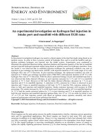
The pull-out tests were conducted following a procedure similar to EN 10080:2005 [6]
and the testing principle is shown in Figure 1. The method was chosen because it has been
standardized and the experimental model can be performed relatively easily, suitable for
available equipment.
Figure 1. The pull-out testing principle.
The principle of the test is to load a bar that is incorporated in a concrete cube, along a
defined length, by a tensile force. The other end of the bar remains without stress. The relation
between the tensile force and the slip (i.e. the relative displacement between steel and
concrete) is measured up to failure. The force is increased up to failure of the bond or until the
reinforcement itself fails.
The test specimen is a cube of concrete where the bar is located in the center of the cube.
The effective bond length of the bar is 5d and corresponds only to a part of the specimen. In
the other part of the bar bond is prevented. The bar to be tested extends beyond the two sides
of the specimen; the tension is applied to the longer end, and the device for measuring the slip
is set on the shorter end.
382
Transport and Communications Science Journal, Vol. 71, Issue 4 (05/2020), 380-387
In this study, the specimens of LWAC for the pull-out test were the cubes of 20x20x20
cm. The 14 mm diameter reinforcements (d) were used and the length of embedment in
concrete samples is 5d. The number of samples tested was six samples. The specimens were
cured in natural conditions for 28 days.
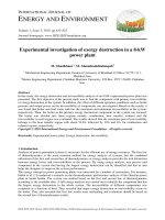
The specimens were tested under the static loading. The loading device is a 20-ton
RCH20-155 hydraulic cylinder (China). The traction is measured by a 30-ton CFBLY loadcell
(China). During the experiment, the measurement data was recorded by using a DRA30A
meter (TML - Japan) connected to the computer with a specialized software. The linear
variable different transducer (LVDT) was installed, respectively, on the free end to measure
the rebar’s displacements; test must be ceased while the displacement of the free end
exceeded 2 mm. The experiments were performed at the Materials and Structural Laboratory,
University of Transport and Communication.
Loading device
Loadcell
LVDT
TML
Computer
Figure 2. The pull – out testing set-up.
III. TEST RESULTS
Experimental results of the pull-out tests are presented in Figure 3. Six load versus slip
curves respectively six sample experiments were observed. The bond behavior between
LWAC and reinforcement consists of 4 stages similar to the one between steel bars and
ordinary concrete [8], [9]. In the first stage, uncracked concrete corresponds to an almost
vertical increasing of the tensile load. At this stage, the bond strength is smaller than tensile
strength of concrete. In the second stage, cracks appear in the concrete surrounding bars
(horizontal cracks, round). At this stage, the stiff decreases and the large strain cause the big
change of the curve slope. In the third stage, bond stress continues to increase. At this stage,
cracks appear along the reinforcement bars and develop to the outside of the structure. When
the peak stress is reached, the slip increases but the load decreases. Finally, the friction
through wedging of the bars deformations on the surrounding concrete becomes the
predominant bond mechanism. The residual bond stress which value is a constant sustains till
the bar pulled out from the LWAC.
383
Transport and Communications Science Journal, Vol. 71, Issue 4 (05/2020), 380-387
The curves are quite similar. The values of the load (stress) measured at the same
displacement are so close, so the experiments results were reliable and accurate.
40
BTN-CT14-M1
35
BTN-CT14-M2
BTN-CT14-M3
Tensile load - P (kN)
30
BTN-CT14-M4
BTN-CT14-M5
25
BTN-CT14-M6
20
15
10
5
0
0
5
10
15
20
25
30
35
40
Slip - S (mm)
Figure 3. The load – slip curves of the test specimens.
The value of average nominal bond stress can be calculated as the normal force divided
by the surface area of the rebar embedded in the concrete. For circular cross section
reinforcing bar of which the diameter is, the average bond strength can be calculated by the
following formula:
fdb = Pmax /( .db .Ldb ), (MPa)
(1)
Where Ldb is the length of embedment and db is the nominal diameter of the
reinforcement. The maximum average bond stress of each specimen can be calculated from
eq. (1) while the maximum tensile load occurs.
The figure 4 presents the bond stress versus slip between rebars and LWAC curves.
14
BTN-CT14-M1
BTN-CT14-M2
12
Bond stress - σ (MPa)
BTN-CT14-M3
BTN-CT14-M4
10
BTN-CT14-M5
BTN-CT14-M6
8
6
4
2
0
0
5
10
15
20
25
30
35
Slip - S (mm)
Figure 4. The bond stress – slip curves of the test specimens.
384
40
Transport and Communications Science Journal, Vol. 71, Issue 4 (05/2020), 380-387
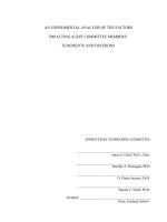
Slipping at the free end of the bar began while the load approached the maximum and
was increasing quickly; then the bar was pulled out. So the specimen was damaged for the
tensile reinforcement was pulled out as shown in Figure 5.
Figure 5. Pull-out failure of specimens.
The nominal stress between rebars 14 and LWAC (f’c = 35MPa) of six experimental
samples varied from 9.75 to 12.45MPa. This result is quite similar to that of Holschemacher
et al. [10]. The tests of pulling the rebars 16 out of LWAC samples (f'cr = 37.98MPa) in the
research of Holschemacher et al. [10] showed the average bond stress from 10.22 to
13.07MPa. As a reason for the number of test samples is not enough to evaluate the
probability, therefore the standard deviation S and the coefficient of variation Cv of the
experimental results were calculated for provide a preliminary assessment of the test results
(Table 3).
Table 3. The average bond stress between rebars 14 and LWAC.
Samples
Pmax
fdb
fdb0,25tb
S
(kN) (MPa) (MPa) (MPa)
1
37.2
12.1
2
31.9
11.4
3
30.3
9.8
4
38.3
12.5
5
35.9
11.7
6
30.0
9.8
11.03
1.189
Cv
0.108
Using the experimental bond stress, the development length of reinforcement (ld)
(minimum length so that steel bars are not pulled out of concrete) in LWAC was calculated
according to the eq. (2); and since the value was compared with the provisions of the
standards.
um =
Ab f y
dbld
=
db2 f y db f y
=
4dbld
4ld
With:
385
(2)
Transport and Communications Science Journal, Vol. 71, Issue 4 (05/2020), 380-387
fy = 300 MPa – yield strength of the steel bars
db = 14 mm (nominal diameter of the steel bars)
um = fdb – average bond stress determined from the tests (table 3)
Table 4. The development length calculated from the test results.
No
um
(MPa)
ld
(mm)
1
12.1
86.8
2
11.4
101.3
3
9.8
106.8
4
12.5
84.3
5
11.7
89.9
6
9.8
107.7
ld
(mm)
S
(mm)
Cv
96.11
10.365
0.1078
Since the Vietnamese standard has no regulations on the development length of
reinforcement in LWAC, the authors compare the experimental results with the foreign
standards. According to ACI 318 [11], the development length of reinforcement (diameter
smaller than 36mm) in concrete is usually calculated by the formula: 0.04*Ab*fy*√fc’. For
lightweight concrete, the development length will be received by multiplying with a
coefficient of 1 – 1.3. According to Eurocode 2-1992 [12], the bond strength of LWAC and
steel reinforcement is lower than that of ordinary concrete (0.67 – 1.0 times, depending on the
density of LWAC. The reduction factor is calculated by the formula 1 = 0.4 + 0.6*0/2200
Using CB300-V grade rebar with a nominal diameter of 14mm and LWAC used, we have:
Ab = 0.2 in2 – area of transversal section of reinforcement
fy = 43511 psi – yield strength of reinforcement
f’c = 5076 psi – nominal compressive strength of LWA
ldb = 4.88 in = 124mm – basic development length of reinforcement in LWAC. This
length is 1.3*ldb in minimum with LWAC structure, determined by the formula in the
paragraph 4.4 – ACI 318 [11].
Thus according the test results, the development length of rebars in LWAC is from 84 to
108mm (about 6db to 8db). This calculated length is smaller than the provisions on the
development length of reinforcement in normal concrete as well as in LWAC of American
standards (ACI 318-11 [11]). Vietnam Standard TCVN 5574 – 2012 [13] specifies that the
minimum anchor length of tensile reinforcement in reinforced concrete structure is 10db. It
can be seen that the arrangement of reinforcement in LWAC as required for the development
length can follow the rules of the standards of TCVN as well as ACI. However, it is necessary
to carry out more experiments in changing the number of samples as well as the material
parameters (compressive strength of LWAC, reinforcement style, ...) for purpose of having
more accurate and reliable results.
386
Transport and Communications Science Journal, Vol. 71, Issue 4 (05/2020), 380-387
IV. CONCLUSIONS
This paper presented some empirical research to determine the bond behavior between
reinforcement and LWAC. Experimental results show that the bond behavior between LWAC
and reinforced steel is similar to the one between steel and ordinary concrete. The average
bond varied from 9.75MPa to 12.45MPa, corresponding to the development length of 84 to
108mm; smaller than the minimum development length specified by ACI 318 - 124mm with
the same material. Preliminary experimental results show that the arrangement and the coworking of reinforcement and LWAC in the structures can comply with the current standards.
However, more samples and test cases might be carried out to get more accurate and general
results.
REFERENCES
[1] H.J. Chen, C.H. Huang, Z.Y. Kao, Experimental investigation on steel-concrete bond in
lightweight and normal weight concrete, Struct. Eng. Mech., 17 (2004) 141–152.
/>[2] W. Yang, J. Yu, Y. Wang, Study on the effect of bond-anchoring factor on bond behavior
between deformed bar and shale ceramic concrete. Adv. Mater. Res, 403 (2012) 444–448.
/>[3] D. Zhang, W. Yang, Experimental research on bond behaviors between shale ceramsite
lightweight aggregate concrete and bars through pullout tests, J. Mater. Civ. Eng., 27(9) (2015).
/>
[4] B. Mayfield and M. Louati, Properties of pelletized blast furnace slag concrete. Mag. Concr. Res.,
42 (150) (1990) 29–36. />[5] BS EN 10080:2005, Steel for the reinforcement of concrete, Weldable reinforcing steel. General.
[6] A. Trad, H. Ghanem, R. Ismail, Bond Behaviour of Structural Lightweight Concrete, in: Hordijk
D., Luković M. (eds) High Tech Concrete: Where Technology and Engineering Meet. Springer, Cham,
2018. />[7] TCVN1651-2: 2008, Thép cốt bê tông – Phần 2: Thanh thép vằn (Concrete reinforcement – Part
2: Deformed steel bar).
[8] Fritz Leohardt, Vorlesung uber Massivebau, 6 vols, Springer Verlag, Berlin, 1975.
[9] fib.CEB-FIP, Bond of reinforcement in concrete - Bulletin 10, International Federation for
Structural Concrete (fib) ed., 2000. />[10] K. Holschemacher, A. Ali, S. Iqbal, Bond of reinforcement in lightweight concrete, in: Insights
and Innovations in Structural Engineering, Mechanics and Computation, Cape Town, South Africa,
2016.
[11] ACI 318-11, Building Code Requirements for Structural Concrete and Commentary.
[12] Eurocode 2-1992, Design of concrete structures – part 1–1: general rules and rules for buildings.
[13] TCVN 5574:2012, Kết cấu bê tông và bê tông cốt thép (Concrete and Reinforced Concrete
Structure).
387