prospects of multilevel VSC technologies for power transmission noi ve HVDC plus dung MMC
Bạn đang xem bản rút gọn của tài liệu. Xem và tải ngay bản đầy đủ của tài liệu tại đây (7.94 MB, 16 trang )
1
Prospects of Multilevel VSC Technologies
for Power Transmission
B. Gemmell, Siemens USA; J. Dorn, D. Retzmann, D. Soerangr, Siemens Germany
Abstract-- Deregulation and privatization are posing new
challenges to high voltage transmission and distributions systems.
System components are loaded up to their thermal limits, and
power trading with fast varying load patterns is leading to an
increasing congestion. In addition to this, the dramatic global
climate developments call for changes in the way electricity is
supplied.
Innovative solutions with HVDC (High Voltage Direct
Current) and FACTS (Flexible AC Transmission Systems) have
the potential to cope with the new challenges. New power
electronic technologies with self-commutated converters provide
advanced technical features, such as independent control of
active and reactive power, the capability to supply weak or
passive networks and less space requirements. In many
applications, the VSC (Voltage-Sourced Converter) has become a
standard for self-commutated converters and will be increasingly
more used in transmission and distribution systems in the future.
This kind of converter uses power semiconductors with turn-off
capability.
II. INTEGRATION OF RENEWABLE ENERGY SOURCES – A
BIG CHALLENGE
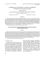
Power output of wind generation can vary fast in a wide
range [3], depending on the weather conditions. Therefore, a
sufficiently large amount of controlling power from the
network is required to substitute the positive or negative
deviation of actual wind power infeed to the scheduled wind
power amount. Fig. 1 shows a typical example of the
conditions, as measured in 2003. Wind power infeed and the
regional network load during a week of maximum load in the
E.ON control area are plotted. The relation between
consumption and supply in this control area is illustrated in
the figure. In the northern areas of the German grid, the
transmission capacity is already at its limits, especially during
times with low load and high wind power generation [11].
This will be a strong Issue in the German Grid Development
Index Terms-- Elimination of Bottlenecks in Transmission;
Enhanced Grid Access for Regenerative Energy Sources (RES);
Increase in Transmission Capacity; Security and Environmental
Sustainability of Supply; Smart Grid Technologies
E
I. INTRODUCTION
NVIROMNMENTAL constraints will play an important
role in the power system developments [1-2]. However,
regarding the system security, specific problems are expected
when renewable energies, such as large wind farms, have to
be integrated into the system, particularly when the connecting
AC links are weak and when sufficient reserve capacity in the
neighboring systems is not available [3]. Furthermore, in the
future, an increasing part of the installed capacity will be
connected to the distribution levels (dispersed generation),
which poses additional challenges to the planning and safe
operation of the systems. Power electronics is to be used to
control load flow, to reduce transmission losses and to avoid
congestion, loop flows and voltage problems [4-6].
In this paper, the basic concept and the technical
performance of the new MMC PLUS technology are
discussed in detail and the area of applications is depicted.
B. Gemmell is with Siemens Power Transmission & Distribution, Inc.,
Wendell, NC 27591 USA (e-mail: ).
J. Dorn, D. Retzmann, D. Soerangr are with Siemens AG, PTD High
Voltage Division, Power Transmission Solutions, 91058 Erlangen, Germany
(e-mails:
,
,
).
Additional Reserve Capacity is
required
Problems with Wind Power Generation:
o Wind Generation varies strongly
o It can not follow the Load Requirements
Source: E.ON - 2003
Fig. 1: Network Load and aggregated Wind Power Generation
during a Week of maximum Load in the E.ON Grid - Example of
Germany
The prospects of embedding large amounts of regenerative
energy sources and dispersed generation into the power
systems are depicted in Fig. 2. It can be seen that this will
have impact on the whole transmission and distribution
network structure. Load flow control will be much more
complex, system control and system protection strategies will
need to be adapted and reserve generation capacity will be
required.
In what follows, the global trends in power markets and the
978-1-4244-1904-3/08/$25.00 ©2008 IEEE
Authorized licensed use limited to: TOKYO INSTITUTE OF TECHNOLOGY. Downloaded on April 7, 2009 at 01:37 from IEEE Xplore. Restrictions apply.
2
prospects of system developments are depicted, and the
outlook for VSC technologies for environmental sustainability
and system security is given.
Tomorrow:
Today:
G
G
G
G
low losses, but the switching speed is relatively low. Power
electronics can provide high switching frequencies up to
several kHz, however, with an increase in losses.
Fig. 3 indicates the typical losses depending on the
switching frequency [16]. It can be seen that due to the low
losses, line-commuted Thyristor technology is the preferred
solution for bulk power transmission, today and in the future.
G
More Dynamics for better Power Quality:
G
G
Use of Power Electronic Circuits for Controlling P, V & Q
Parallel and/or Series Connection of Converters
Fast AC/DC and DC/AC Conversion
Depending
on Solution
2-4 %
G
H
G
G
G
G
H
H
Transition from “slow” to “fast”
Use of Dispersed Generation
Fig. 2: Regenerative Energy Sources and Dispersed Generation –
Impact on the whole T&D Grid Structure
III. SMART GRID SOLUTIONS WITH POWER ELECTRONICS
The vision and enhancement strategy for the future
electricity networks is depicted in the program of
“SmartGrids”, which was developed within the European
Technology Platform (ETP) of the EU in its preparation of the
7th Frame Work Program.
Features of a future “SmartGrid” of this kind can be
outlined as follows [1, 18]:
• Flexible: fulfilling customers’ needs whilst responding to
the changes and challenges ahead
• Accessible: granting connection access to all network
users, particularly to RES and highly efficient local
generation with zero or low carbon emissions
• Reliable: assuring and improving security and quality of
supply
• Economic: providing best value through innovation,
efficient energy management and ‘level playing field’
competition and regulation
It is worthwhile mentioning that the Smart Grid vision is in
the same way applicable to the system developments in other
regions of the world. Smart Grids will help achieve a
sustainable development. The key to achieve a Smart Grid
performance will be the use of power electronics.
A. HVDC and FACTS Technologies
HVDC systems and FACTS controllers based on linecommutated converter technology (LCC) have a long and
successful history. Thyristors have been the key components
of this converter topology and have reached a high degree of
maturity due to their robust technology and their high
reliability. HVDC and FACTS with LCC use power electronic
components and conventional equipment which can be
combined in different configurations to switch or control
reactive power, and to convert the active power. Conventional
equipment (e.g. breakers, tap-changer transformers) has very
Thyristor
GTO
1-2 %
Load Flow will be “fuzzy”
Switching
Frequency
> 1000 Hz
< 500 Hz
50/60 Hz
IGBT / IGCT
Losses
On-Off Transition 20 - 80 ms
The Solution for Bulk Power Transmission
Fig. 3: Power Electronics for HVDC and FACTS – Transient
Performance and Losses
It is, however, necessary to mention that line-commutated
converters have some technical restrictions. Particularly the
fact that the commutation within the converter is driven by the
AC voltages requires proper conditions of the connected AC
system, such as a minimum short-circuit power.
B. Voltage-Sourced Converters
Power electronics with self-commutated converters can
cope with the limitations mentioned above and provide
additional technical features. In DC transmission, an
independent control of active and reactive power, the
capability to supply weak or even passive networks and lower
space requirements are some of the advantages. In many
applications, the VSC has become a standard of selfcommutated converters and will be used more often in
transmission and distribution systems in the future. Voltagesourced converters do not require any “driving” system
voltage; they can build up a 3-phase AC voltage via the DC
voltage. This kind of converter uses power semiconductors
with turn-off capability such as IGBTs (Insulated Gate Bipolar
Transistors).
Up to now, the implemented VSC converters for HVDC
applications have been based on two or three-level technology
which enables switching two or three different voltage levels
to the AC terminal of the converter. To make high voltages in
HVDC
transmission
applications
controllable
by
semiconductors with a blocking ability of a few kilovolts,
multiple semiconductors are connected in series – up to
several hundred per converter leg, depending on the DC
voltage. To ensure uniform voltage distribution not only
statically but also dynamically, all devices connected in series
in one converter leg have to switch simultaneously with the
accuracy in the microsecond range. As a result, high and steep
Authorized licensed use limited to: TOKYO INSTITUTE OF TECHNOLOGY. Downloaded on April 7, 2009 at 01:37 from IEEE Xplore. Restrictions apply.
3
voltage steps are applied at the AC converter terminals which
require extensive filtering measures. In Fig. 4, the principle of
two-level converter technology is depicted. From the figure, it
can be seen that the converter voltage, created by PWM
(Pulse-Width Modulation) pulse packages, is far away from
the desired “green” voltage, it needs extensive filtering to
approach a clean sinus waveform.
+Vd /2
0
Vd /2
)
VConv.
Vd /2
- Vd /2
Desired voltage
Realized voltage
High harmonic Distortion
High Stresses resulting in HF Noise
Fig. 4: VSC Technology – a Look back
C. The Modular Multilevel Converter (MMC) Approach
Both the size of voltage steps and the related voltage
gradients can be reduced or minimized if the AC voltage
generated by the converter can be selected in smaller
increments than at two or three levels only.
Topologies: Two-Level
GTO / IGCT
The finer this gradation, the smaller is the proportion of
harmonics and the lower is the emitted high-frequency
radiation. Converters with this capability are called multilevel
converters.
Furthermore, the switching frequency of individual
semiconductors can be reduced. Since each switching event
creates losses in the semiconductors, converter losses can also
be effectively reduced.
Different multilevel topologies [7-10], such as diode
clamped converter or converters with what is termed “flying
capacitors” were proposed in the past and have been discussed
in many publications.
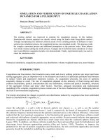
In Fig. 5, a comparison of two, three and multilevel
technology is depicted. A new and different multilevel
approach is the modular multilevel converter (MMC)
technology [9].
The principle design of conventional multilevel converter
and advanced MMC is shown in Fig. 6 and Fig. 7 depicts the
HVDC PLUS MMC solution in detail.
A converter in this context consists of six converter legs,
whereas the individual converter legs consist of a number of
submodules (SM) connected in series with each other and
with one converter reactor.
Each of the submodules contains [9, 16, 17]:
- an IGBT half bridge as switching element
- a DC storage capacitor
Three-Level
IGBT in PP
Multilevel
IGBT Module
Power
Electronic
Devices:
Fig. 5: The Evolution of VSC and HVDC PLUS Technology
Authorized licensed use limited to: TOKYO INSTITUTE OF TECHNOLOGY. Downloaded on April 7, 2009 at 01:37 from IEEE Xplore. Restrictions apply.
4
a)
b)
Vd / 2
Vd
VConv.
Vd / 2
VConv.
Small Converter AC Voltage Steps
Small Rate of Rise of Voltage
Low Generation of Harmonics
Low HF Noise
c)
Low Switching Losses
Fig. 6: The Multilevel Approach
a) Conventional Solution
b) Advanced MMC Solution
c)
Sinus
Approximation
–
and
Submodule (SM)
Vd
Fig. 7: HVDC PLUS – Basic Scheme
For the sake of simplicity, the electronics for controlling
the semiconductors, measuring the capacitor voltage and for
communicating with the higher-level control are not shown in
Fig. 7. Three different states are relevant for the proper
operation of a submodule, as illustrated in Table I:
1. Both IGBTs are switched off:
This can be compared to the blocked condition of a twolevel converter. Upon charging, i.e. after closing the AC
power switch, all submodules of the converter are in
this condition. Moreover, in the event of a serious failure all
submodules of the converter are put in this state. During
normal operation with power transfer, this condition does
not occur. If the current flows from the positive DC pole in
the direction of the AC terminal during this state, the flow
passes through the capacitor of the submodule and charges
the capacitor. When it flows in the opposite direction, the
freewheeling diode D2 bypasses the capacitor.
Authorized licensed use limited to: TOKYO INSTITUTE OF TECHNOLOGY. Downloaded on April 7, 2009 at 01:37 from IEEE Xplore. Restrictions apply.
5
2. IGBT1 is switched on, IGBT2 is switched off
Irrespective of the current flow direction, the voltage of the
storage capacitor is applied to the terminals of the
submodule. Depending on the direction of flow, the current
either flows through D1 and charges the capacitor, or
through IGBT1 and thereby discharges the capacitor.
It is thereby possible to separately and selectively control
each of the individual submodules in a converter leg. So, in
principle, the two converter legs of each phase module
represent a controllable voltage source. In this arrangement,
the total voltage of the two converter legs in one phase unit
equals the DC voltage, and by adjusting the ratio of the
converter leg voltages in one phase module, the desired
sinusoidal voltage at the AC terminal can easily be achieved.
Fig. 8 depicts this advanced principle of AC voltage
generation with MMC. It can be seen that there is almost no or
– in the worst case – very small need for AC voltage filtering
to achieve a clean voltage, in comparison with the two-level
circuit with PWM in Fig. 4.
3. IGBT1 is switched off, IGBT2 is switched on:
In this case, the current either flows through IGBT2 or D2
depending on its direction which ensures that zero voltage
is
applied to the terminals of the submodule (except for the
conducting-state voltage of the semiconductors). The
voltage in the capacitor remains unchanged.
TABLE I
STATES AND CURRENT PATHS OF A SUBMODULE IN THE MMC TECHNOLOGY
State11
State
State 2
State 2
State33
State
Off
On
Off
Off
Off
On
Off
On
Off
Off
Off
On
AC and DC Voltages controlled
by Converter Leg Voltages:
+Vd / 2
VAC
VConv.
0
- Vd / 2
Fig. 8: The Result – MMC, a perfect Voltage Generation
Authorized licensed use limited to: TOKYO INSTITUTE OF TECHNOLOGY. Downloaded on April 7, 2009 at 01:37 from IEEE Xplore. Restrictions apply.
6
As is true in all technical systems, sporadic faults of
individual components during operation cannot be excluded,
even with the most meticulous engineering and 100-percent
routine test. However, if a fault occurs, the operation of the
system must not be impeded as a result. In the case of an
HVDC transmission system this means that there must be no
interruption of the energy transfer and that the system will
actually continue to operate until the next scheduled shutdown for maintenance.
Redundant submodules are therefore integrated into the
converter, and, unlike in previous redundancy concepts, the
unit can now be designed so that, upon failure of a submodule
in a converter leg, the remaining submodules are not subjected
to a higher voltage. The inclusion of the redundant
submodules thus merely results in an increase in the number
of submodules in a converter leg that deliver zero voltage at
their output during operation. In the event of a submodule
failure during operation this fault is detected and the defective
submodule is shorted out by a highly reliable high-speed
bypass switch, ref. to Fig. 9. This provides fail-safe
functionality, as the current of the failed module can continue
to flow, and the converter continues to operate, without any
interruption.
possible, evaluation of the feedback and selective switching of
the individual submodules can be used to balance the
submodule voltages. With this approach, the capacitor
voltages of all submodules of a converter leg in HVDC PLUS
are maintained within a defined voltage band.
From the perspective of the DC circuit, the described
topology looks like a parallel connection of three voltage
sources – the three phase units that generate all desired DCvoltages. In practice, there will be little difference between the
momentary values of the three DC voltages, if for no other
reason than that the number of available voltage steps is finite.
To dampen the resulting balancing currents between the
individual phase units, and to reduce them to a very low value
by means of appropriate control methods, a converter reactor
is integrated into the individual converter legs. In addition to
the aforementioned function, these reactors are also used to
substantially reduce the effects of faults arising within or
outside the converter. As a result, unlike in previous VSC
topologies, current rise rates of only a few tens of amperes per
microsecond are encountered even in so far very critical
faults.
These faults are swiftly detected, and, due to the low
current rise rates, the IGBTs can be turned off at absolutely
uncritical current levels. This capability thus provides very
effective and reliable protection of the system.
PLUSCONTROL
High-Speed Bypass Switch
Phase Unit
Fig. 9: MMC – Redundant Submodule Design
As in all multilevel topologies it is necessary to ensure,
within certain limits, a uniform voltage distribution across the
individual capacitors of the multilevel converter. When using
the MMC topology for HVDC this is achieved by periodic
feedback of the current capacitor voltage to a central control
unit. The time intervals between these feedback events are less
than 100 microseconds.
Due to the fact that in each line cycle in the converter leg,
current flow occurs both in one and in the other direction and
that charging or discharging of the individual capacitors is
Submodule
The following describes a very interesting fault occurrence:
In the event of a short-circuit between the DC terminals of
the converter or along the transmission route, the current rises
in excess of a certain threshold value in the converter legs,
and, due to the aforementioned limitation of the speed in the
current rise, the IGBTs can be switched off within a few
microseconds before the current can reach a critical level,
which provides an effective protective function. Thereafter –
as with any VSC topology – current flows from the threephase line through the free-wheeling diodes to the shortcircuit, so that the only way this fault can be corrected is by
opening the circuit breaker.
Authorized licensed use limited to: TOKYO INSTITUTE OF TECHNOLOGY. Downloaded on April 7, 2009 at 01:37 from IEEE Xplore. Restrictions apply.
7
The free-wheeling diodes used in VSC converters have a
low capacity for withstanding surge current events related to
their silicon surface, i.e. only a very limited ability to
withstand a surge in current without sustaining damage. In an
actual event, the diodes would have to withstand a surge fault
current without damage until the circuit breaker opens, i.e. in
most cases for at least three line cycles. In HVDC PLUS, a
protective function at the submodule level effectively reduces
the load of the diodes until the circuit breaker opens. This
protective measure consists of a press-pack thyristor, which is
connected in parallel to the endangered diode and is fired in
the event of a fault, ref to Fig. 10.
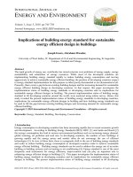
by assembling them in a vertical arrangement to meet the
specific project requirements.
Fig. 11 depicts a view of the MMC design. In principle,
both a standing and a suspended construction can be readily
achieved. However, a standing construction was chosen, since
in that case the converter design imposes less specific
requirements on the converter building.
If required in specific projects, highly effective protective
measures against severe seismic loads can also be
implemented (ref. to Fig. 11). For such a situation, provisions
have been made for diagonal braces at the individual units that
ensure adequate stability of the construction.
PLUSCONTROL
Protective Thyristor Switch
SM electronics
IGBT1
1
Phase Unit
D1
IGBT2
D2
Submodule
2
Fig. 10: Fully suitable for DC OHL Application – Example Line-to-Line Fault
As a result, most of the fault current flows through the
thyristor and not through the diode it protects. Press-pack
thyristors are known for their high capability to withstand
surge currents. This characteristic is also useful in
conventional,
line-commutated
HVDC
transmission
technology. This fact makes HVDC PLUS suitable even for
overhead transmission lines, an application previously
reserved entirely for line-commutated converters with
thyristors.
Thanks to its modular construction, the HVDC PLUS
converter is extremely well scalable, i.e. conveniently
adaptable to any required power and voltage ratings. The
mechanical construction adheres consistently to the modular
design. Sets of six modules are assembled to form
transportable units that are easy to install with the proper
tools. The required number per converter leg can be optimally
realized by a horizontal array of such units and – if required –
The submodules are connected bi-directionally via fiber
optics with the PLUSCONTROL (Fig. 12), the central control
unit. The PLUSCONTROL was developed specifically for
HVDC PLUS and has the following functions:
- Calculation of appropriate converter leg voltages at time
intervals of several microseconds
- Selective actuation of the submodules depending on the
direction of current flow and on the relevant capacitor
voltages in the submodules so as to assure reliable
balancing of capacitor voltages
In addition to the current status of each submodule, the
momentary voltage of the capacitor is communicated via the
fiber optics to the PLUSCONTROL. Control signals to the
submodule, such as the signals for the switching of the IGBTs,
are communicated in the opposite direction from the
PLUSCONTROL to the submodules.
Authorized licensed use limited to: TOKYO INSTITUTE OF TECHNOLOGY. Downloaded on April 7, 2009 at 01:37 from IEEE Xplore. Restrictions apply.
8
Typical Converter Arrangement for 400 MW
Optional
Seismic
Reinforcements
Converter Leg with more than 200 Submodules
Fig. 11: HVDC PLUS – The Advanced MMC Technology
Calculation of required
Converter Leg Voltages
Control of Active and
Reactive power
Selection of Submodules
to be switched
Submodule Voltage
Balancing Control
SIMATIC TDC
Measuring System
SIMATIC TDC
C&P System
Fig. 12: Main Tasks of PLUSCONTROL TM
Key features of the PLUSCONTROL are:
- Mechanical construction in standard 19-inch racks
- High modularity and scalability through plug-in modules,
and the capability of integrating different numbers of
racks into the system
- Uniform redundancy concept with an active and passive
system and the ability to change over on the fly
- Modules and fans can be replaced during operation
- Sufficient interfaces for communication and control of
well over 100 submodules per rack
- High performance with respect to computational power
and logic functions
The PLUSCONTROL was integrated into the industryproven Simatic TDC environment, which provides the
platform for the measuring system and the higher-level control
and protection.
The MMC topology used in HVDC PLUS differs from
other, already familiar VSC topologies in design, mode of
operation, and protection capabilities. The following
summarizes the essential differences and related advantages:
Authorized licensed use limited to: TOKYO INSTITUTE OF TECHNOLOGY. Downloaded on April 7, 2009 at 01:37 from IEEE Xplore. Restrictions apply.
9
- A highly modular construction both in the power section
and in control and protection has been chosen. As a result,
the system has excellent scalability and the overall design
can be engineered very flexible. Thus, the converter
station can be perfectly adapted to the local
requirements, and depending on those requirements, the
design can favor a more vertical or more horizontal
construction. The use of HVDC can therefore become
technically and economically feasible starting from
transmission rates of several tens of megawatts
- In normal operation, no more than one level per converter
leg switches at any given time. As a result, the AC
voltages can be adjusted in very fine increments and a DC
voltage with very little ripple can be achieved, which
minimizes the level of generated harmonics and in most
cases completely eliminates the need for AC filters.
What’s more, the small and relatively shallow voltage
steps that do occur cause very little radiant or conducted
high-frequency interference
- The low switching frequency of the individual semiconductors results in very low switching losses. Total system
losses are therefore relatively low for VSC PLUS technology, and the efficiency is consequently higher in comparison with existing two and three-level solutions
- HVDC PLUS utilizes industrially proven standard components that are very robust and highly reliable, such as
IGBT modules. These components have proven their
reliability and performance many times over under severe
environmental and operating conditions in other
applications, such as traction drives. This wide range of
applications results in a larger number of manufacturers
as well as long-term availability and continuing
development of these standard components
- The encountered voltage and current loads support the
use of standard AC transformers
- The achievable power range as well as the achievable DC
voltage of the converter is determined essentially only by
the performance of the controls, i.e. the number of
submodules that can be operated. With the current design,
transmission rates of 1000 MW or more can be achieved
- Due to the elimination of additional components such as
AC filters and their switchgear, high reliability and
availability can be achieved. What’s more, the
elimination of components and the modular design can
shorten project execution times, all the way from project
development to commissioning
- With respect to later provision of spare-parts, it is easy to
replace existing components by state-of-the-art components, since the switching characteristics of each
submodule are determined independently of the behavior
of the other submodules. This is an important difference
to the direct series-connection of semiconductors, such
as in the two-level technology, where nearly identical
switching characteristics of the individual semiconductors
are mandatory
- Internal and external faults, such as short-circuit between
the two DC poles of the transmission line, are reliably
managed by the system, due to the robust design and the
fast response of the protection functions
Figs. 13-15 summarize the advantages in a comprehensive
way. Added to these are the aforementioned advantages that
ensue from the use of VSC technology in general. With these
features, HVDC PLUS is ideally suitable for the following DC
systems (Fig. 16):
- Cable transmission systems. Here, the use of modern
extruded cables, i.e. XLPE, is possible, since the voltage
polarity in the cable remains the same irrespective of the
direction of current flow
- Overhead transmission lines, because of the capability to
manage DC side short-circuits and prompt resumption of
system operation
- Back-to-back arrangement, i.e. rectifier and inverter in
one station
- The implementation of multiterminal systems is relatively simple with HVDC PLUS. In these systems, more than
two converter stations are linked to a DC connection. It is
even possible to configure complete DC networks with
branches and ring structures. The future use for systems
such as these was addressed in the development of
HVDC PLUS by pre-engineering the control strategies
required for them
- It goes without saying that the converters can also be
used as STATCOMS, e.g. when the transmission line or
cable is out of service during maintenance or faults.
STATCOM with PLUS technology is also useful in
unbalanced networks, for instance in the presence of
large single-phase loads. Symmetry of the three-phase
system can to some extent be restored by using load
unbalance control
This multitude of possibilities in combination with the
performance of HVDC PLUS opens up a wide range of
applications for this technology:
- DC connections for a power range of up to 1,000 megawatts, in which presently only line-commutated
converters are used
- Grid access to very weak grids or islanded networks
- Grid access of renewable energy sources, such as offshore
wind farms, via HVDC PLUS. This can substantially help
reduce CO2 emissions. And vice versa, oil platforms can
be supplied from the coast via HVDC PLUS, so that gas
turbines or other local power generation on the
platform can be avoided.
Furthermore, with its space-saving design and technical
performance, HVDC PLUS is tomorrow’s solution for the
supply of megacities.
To achieve transmission redundancy, HVDC PLUS can be
configured in two ways, as depicted in Fig. 17. Option a) is
the standard solution, providing a full n-1 redundancy for the
whole transmission scheme, including cable or line. Option b)
can be selected, when cost saving for one cable/line conductor
is required.
In this case, however, standard AC transformers can not be
used, HVDC transformers would be required.
Authorized licensed use limited to: TOKYO INSTITUTE OF TECHNOLOGY. Downloaded on April 7, 2009 at 01:37 from IEEE Xplore. Restrictions apply.
10
High Modularity in Hardware
and Software
Low Generation of Harmonics
Low Switching Frequency of
Semiconductors
Use of well-proven Standard
Components
Sinus shaped AC Voltage
Waveforms
Easy Scalability
a)
Reduced Number of Primary
Components
Low Rate of Rise of Currents
even during Faults
High Flexibility, economical
from low to high Power Ratings
Only small or even no Filters
required
Low Converter Losses
High Availability of State-ofthe-Art Components
Use of standard AC
Transformers
Low Engineering Efforts,
Power Range up to 1000 MW
High Reliability, low
Maintenance Requirements
Robust System
Space
Saving
HVDC PLUS
Example 400 MW
b)
HVDC
“Classic”
Fig. 13: a) Features and Benefits of MMC Topology
b) Space Saving in Comparison with HVDC “Classic”
Authorized licensed use limited to: TOKYO INSTITUTE OF TECHNOLOGY. Downloaded on April 7, 2009 at 01:37 from IEEE Xplore. Restrictions apply.
11
Low Switching Frequency
DC Cable Transmission
DC Cable Transmission
Reduction in Losses
DC Overhead Line Transmission
DC Overhead Line Transmission
Less Stresses
Back-to-Back Systems
Back-to-Back Systems
In Comparison with 2 and
3-Level Converter
Technologies
Multiterminal Systems
Multiterminal Systems
STATCOM Features included
STATCOM Features included
… with Advanced VSC Technology
= = =
= = =
~ ~ ~
~ ~ ~
= = =
Fig. 16: Applications and Features of
= = =
HVDC PLUS
Clean Energy to Platforms & Islands …
G~
Fig. 14: HVDC PLUS – The Power Link Universal System
= = =
= = =
= = =
= = =
~ ~ ~
= = =
= = =
~ ~ ~
~ ~ ~
~ ~ ~
~ ~ ~
~ ~ ~
~ ~ ~
~ ~ ~
= = =
= = =
= = =
= = =
= = =
= = =
= = =
= = =
= = =
= = =
= = =
~ ~ ~
= = =
= = =
~ ~ ~
~ ~ ~
~ ~ ~
~ ~ ~
~ ~ ~
~ ~ ~
~ ~ ~
= = =
= = =
= = =
= = =
= = =
= = =
= = =
HVDC PLUS – One Step ahead
Compact Modular Design
Less Space Requirements
Advanced VSC Technology
Fig. 15: HVDC PLUS – The Smart Way
= = =
= = =
~ ~ ~
~ ~ ~
= = =
= = =
G~
G~
b)
G~
= = =
= = =
~ ~ ~
~ ~ ~
= = =
HVDC Transformers
required
= = =
Use of Standard AC Transformers
Fig. 17: Options a) and b) for
a)
Transmission Redundancy
Authorized licensed use limited to: TOKYO INSTITUTE OF TECHNOLOGY. Downloaded on April 7, 2009 at 01:37 from IEEE Xplore. Restrictions apply.
12
D. Benefits of Active AC and DC Filters
Active filters with VSC offer many benefits in comparison
with passive filters only. In high voltage systems, the active
filters are used in combination with passive filters. By means
of their controls, they can “track” the system frequency, and
they can filter several harmonics at the same time:
- Excellent performance even in case of detuning of the
passive filter or variation of system frequency
- Superior harmonic performance through the elimination
of several harmonics simultaneously with a single active
filter
- Less resonance frequencies due to interaction with
network impedance or other filters, capacitors, reactors
- Easy adaptation to existing passive filter schemes
- Containerized design allows to test the complete system
at the factory and reduces commissioning works
- Active filters meet the highest harmonic performance,
which is an important environmental issue in cities and
megacities
This technology which uses VSC has been successfully
applied since long. An example for the AC side application in
Europe at HVDC station Skagerak III is shown in Fig. 18.
For DC filtering, Fig. 19 shows the results, measured at
Tian-Guang HVDC station in China. The figures 18-19 show
that active filters significantly improve the power quality on
the AC and DC side respectively. In Fig. 18, the containerized
active filter (blue “box”) is positioned close to the associated
passive filters of the HVDC station.
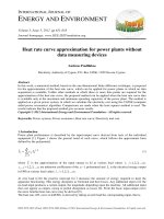
For the Neptune HVDC project in USA, a superior
harmonic performance on the AC side of the DC transmission
system was required due to the power quality requirements
[16]. Adhering to these very tight requirements was not
possible with passive filters alone. For flexibility reasons, the
MMC concept was also introduced in the new active filter
development for the Neptune project. Highlights of this new
design (ref. to Fig. 20), already fully proven in practice, are as
follows:
- The rating has been increased to 26 kV 600 ARMS
- Up to 16 independent harmonic frequencies can be
mitigated with either voltage or current control
- Active damping is possible. The energy balance is
maintained by the fundamental frequency component
- The main circuit is independent of auxiliary power
Multilevel converter technology renders the power
transformer superfluous.
Only Passive
5 7
11 13
23 25
Harmonic numbers
Passive + Active
35 37
47 49
5 7
11 13
23 25
Harmonic numbers
35 37
47 49
Remark: the Output of the Measuring System is proportional to the Frequency
400 kV AC On-Site
Measurements
Fig. 18: Active Filter for AC Side – HVDC Skagerrak III, Nordel Europe
Authorized licensed use limited to: TOKYO INSTITUTE OF TECHNOLOGY. Downloaded on April 7, 2009 at 01:37 from IEEE Xplore. Restrictions apply.
13
Comparison of DC Currents with passive Filter alone (yellow) and
with active Filter inserted (green). Power: 450 MW (0.5 pu) per Pole.
500 kV DC On-Site
Measurements
Fig. 19: Active Filter for DC Side – HVDC Tian-Guang, China
a)
Topology:
Passive AC Filter
b)
Switchgear
HF Filter and IGBT
Converter
Fig. 20: Advanced Active Filter for AC using MMC Technology – a) Application for Neptune HVDC, Site View, b) Topology
Authorized licensed use limited to: TOKYO INSTITUTE OF TECHNOLOGY. Downloaded on April 7, 2009 at 01:37 from IEEE Xplore. Restrictions apply.
14
E. STATCOM with MMC Technology – SVC PLUS
It is obvious that the advanced MMC technology can also
be applied to STATCOM with benefits similar to those of
HVDC PLUS. With respect to technology similarities and
synergies, the decision was made to use the active filter
modules for the STATCOM application in combination with a
power transformer.
The concept and the compact, modular design of the
SVC PLUS development with MMC technology
summarized in Figs. 21 and 22.
In the figures, synergies with the active filter
highlighted. It can be seen, that the SVC PLUS solution
the same H-Bridge modules as the active filter.
new
are
are
uses
VSC
b)
Similar Benefits
in Comparison
a)
with HVDC
VSC
PLUS
Fig. 21: From Active Filter - a) to SVC PLUS - b)
Control System
Modul #1
Modul #2
Modul #6
Modul #4
Cooling System
Modul #7
Modul #3
Modular Multilevel Converter
Modul #8
Modul #5
Fig. 22: SVC PLUS – The Advanced STATCOM
a) Converter with H-Bridge Modules
b) A View on the Technology – Containerized Solution
Authorized licensed use limited to: TOKYO INSTITUTE OF TECHNOLOGY. Downloaded on April 7, 2009 at 01:37 from IEEE Xplore. Restrictions apply.
15
IV. CONCLUSIONS
The new Modular Multilevel Converter technology (MMC)
for HVDC PLUS and SVC PLUS provides tremendous
benefits for power transmission. It will help significantly in
increasing sustainability and security for transmission
systems.
In future, a combination of the different transmission
technologies may offer additional benefits for the power
systems. This idea is outlined in Fig. 23.
= = =
= = =
= = =
= = =
= = =
= = =
= = =
= = =
= = =
= = =
= = =
= = =
= = =
= = =
= = =
= = =
= = =
= = =
= = =
= = =
= = =
= = =
~ ~ ~
HVDC PLUS – from
Offshore to Land
Its basis is the widely promoted political intention to install
huge amounts of wind energy, most on offshore platforms, in
Europe and in Germany in particular. The transmission
scenario, as depicted in the figure, uses both Bulk Power
HVDC Classic and HVDC PLUS each “on its place”. The
goal is a significant CO2 reduction through the replacement of
conventional power plants by renewable energy sources,
mainly offshore wind farms [2], however, without
jeopardizing the system security [12-15], as indicated in the
figure.
~ ~ ~
= = =
= = =
= = =
= = =
= = =
= = =
= = =
= = =
= = =
= = =
= = =
= = =
= = =
= = =
= = =
= = =
= = =
= = =
= = =
= = =
= = =
= = =
Vattenfall
Europe Transmission
HVDC Classic – for Load &
Generation Reserve Sharing
Fig. 23: Conclusions – Integration of large Offshore Wind Farms into the Main Grid
Prospects of HVDC in Germany
V. REFERENCES
[1]
“European Technology Platform SmartGrids – Vision and Strategy for
Europe’s Electricity Networks of the Future”, 2006, Luxembourg,
Belgium
[2]
DENA Study Part 1, “Energiewirtschaftliche Planung für die
Netzintegration von Windenergie in Deutschland an Land und Offshore
bis zum Jahr 2020”, February 24, 2005, Cologne, Germany
[3]
[4]
[5]
M. Luther, U. Radtke, “Betrieb und Planung von Netzen mit hoher
Windenergieeinspeisung”, ETG Kongress, October 23-24, 2001,
Nuremberg, Germany
“Economic Assessment of HVDC Links”, CIGRE Brochure Nr.186
(Final Report of WG 14-20)
N.G. Hingorani, “Flexible AC Transmission”, IEEE Spectrum, pp. 4045, April 1993
[6]
“FACTS Overview”, IEEE and CIGRE, Catalog Nr. 95 TP 108
[7]
Working Group B4-WG 37 CIGRE, “VSC Transmission”, May 2004
[8]
F. Schettler, H. Huang, N. Christl, “HVDC Transmission Systems using
Voltage-sourced Converters – Design and Applications”, IEEE Power
Engineering Society Summer Meeting, July 2000
[9]
R. Marquardt, A. Lesnicar, “New Concept for High Voltage – Modular
Multilevel Converter”, PESC 2004 Conference, Aachen, Germany
[10] S. Bernet, T. Meynard, R. Jakob, T. Brückner, B. McGrath, “Tutorial
Multi-Level Converters”, Proc. IEEE-PESC Tutorials, 2004, Aachen,
Germany
[11] L. Kirschner, D. Retzmann, G. Thumm, “Benefits of FACTS for Power
System Enhancement”, August 14-18, 2005, IEEE/PES T & D
Conference, Dalian, China
[12] G. Beck, D. Povh, D. Retzmann, E. Teltsch, “Global Blackouts –
Lessons Learned”, Power-Gen Europe, June 28-30, 2005, Milan, Italy
[13] G. Beck, D. Povh, D. Retzmann, E. Teltsch, “Use of HVDC and
FACTS for Power System Interconnection and Grid Enhancement”,
Power-Gen Middle East, January 30 – February 1, 2006, Abu Dhabi,
United Arab Emirates
Authorized licensed use limited to: TOKYO INSTITUTE OF TECHNOLOGY. Downloaded on April 7, 2009 at 01:37 from IEEE Xplore. Restrictions apply.
16
[14] W. Breuer, D. Povh, D. Retzmann, E. Teltsch, “Trends for future HVDC
Applications”, 16th CEPSI, November 6-10, 2006, Mumbai, India
[15] G. Beck, W. Breuer, D. Povh, D. Retzmann, “Use of FACTS for
System Performance Improvement”, 16th CEPSI, November 6-10, 2006,
Mumbai, India
[16] J. M. Pérez de Andrés, J. Dorn, D. Retzmann, D. Soerangr, A. Zenkner,
“Prospects of VSC Converters for Transmission System Enhancement”;
PowerGrid Europe 2007, June 26-28, Madrid, Spain
[17] J. Dorn, H. Huang, D.Retzmann, “Novel Voltage-Sourced Converters
for HVDC and FACTS Applications”, Cigre Symposium, November 14, 2007, Osaka, Japan
Dag Soerangr was born in Oslo, Norway, on April
22, 1953. He graduated in Electrical Engineering
(Dipl.-Ing.) at the University of Trondheim, the
Norwegian Institute of Technology (NTH) in 1976.
Dag Soerangr joined Siemens Norway in 1978
and has been with Siemens AG in Erlangen since
1996. His experience includes project development,
sales and marketing for HVDC projects, HVDC
system design, project management for hydroelectric
generators, project management for offshore safety
systems and automation systems and engineering as
well as commissioning of high voltage installations and automation systems in
power plants, substations and petrochemical plants.
[18] W. Breuer, D. Povh, D. Retzmann, Ch. Urbanke, M. Weinhold,
“Prospects of Smart Grid Technologies for a Sustainable and Secure
Power Supply”, The 20TH World Energy Congress, November 11-15,
2007, Rome, Italy
VI. BIOGRAPHIES
Brian D. Gemmell (M’00) received his MEng and
PhD in Electrical and Electronic Engineering from
the University of Strathclyde, UK in 1990 in 1995
respectfully. During 1992, he spent 6 months as a
Visiting Engineer at the Massachusetts Institute of
Technology. He worked for ScottishPower (19942000) in Substation Engineering and Transmission
Planning. He has spent the past 7 years working in
FACTS & HVDC Business Development and is
currently Director of Business Development with
Siemens Power Transmission & Distribution, Inc.,
based in Wendell, NC.
Joerg Dorn was born in Forchheim, Germany, on
March 7, 1969. He has graduated in Electrical
Engineering (Dipl.-Ing.) at the University of
Erlangen-Nuremberg, Germany in 1996.
His employment experience included Eupec
GmbH, Infineon Technology and Siemens. He has
worked in the fields of application of high power
semiconductors, design of power stacks for HVDC
and medium voltage drives, development and
application of high power converters.
Currently, he is principal engineer and director
for the development of HVDC PLUS in High Voltage Division, Power
Transmission Solutions of Siemens. Mr. Dorn is active in Cigré and IEC in
different working groups.
Dietmar Retzmann was born in Pfalzfeld, Germany,
on November 4, 1947. He graduated in Electrical
Engineering (Dipl.-Ing.) at the Technische
Hochschule Darmstadt, Germany in 1974 and he
received Dr.-Ing. degree from the University of
Erlangen-Nuremberg, Germany in 1983.
Dr. Retzmann is with Siemens Erlangen,
Germany since 1982. Currently, he is director for
Technical Marketing & Innovations HVDC/FACTS
in High Voltage Division, Power Transmission
Solutions.
His area of expertise covers project development, simulation and testing of
HVDC, FACTS, System Protection and Custom Power as well as system
studies, innovations and R&D activities.
Dr. Retzmann is active in Cigré, IEEE, ZVEI and VDE. He is author and
co-author of over 160 technical publications in international journals and
conferences. In 1998, he was appointed guest-professor at Tsinghua
University, Beijing, and in 2002 at Zhejiang University, Hangzhou, China.
Since 2004, he is lecturer on Power Electronics at the University of Karlsruhe,
Germany. Since 2004, he gives lectures on HVDC/FACTS at the University
of Karlsruhe, Germany. In 2006, he was nominated “Siemens TOP Innovator”.
Authorized licensed use limited to: TOKYO INSTITUTE OF TECHNOLOGY. Downloaded on April 7, 2009 at 01:37 from IEEE Xplore. Restrictions apply.