Solution manual for feedback control of dynamic systems 7th edition by franklin
Bạn đang xem bản rút gọn của tài liệu. Xem và tải ngay bản đầy đủ của tài liệu tại đây (1.31 MB, 11 trang )
Solution Manual for Feedback Control of Dynamic Systems 7th Edition by Franklin
Full file at />
1000
Solutions Manual: Chapter 1
7th Edition
Feedback Control of Dynamic
Systems
Gene F. Franklin
J. David Powell
Abbas Emami-Naeini
Assisted by:
H. K. Aghajan
H. Al-Rahmani
P. Coulot
P. Dankoski
S. Everett
R. Fuller
T. Iwata
V. Jones
F. Safai
L. Kobayashi
H-T. Lee
E. Thuriyasena
M. Matsuoka
© 2015 Pearson Education, Inc., Upper Saddle River, NJ. All rights reserved. This publication is protected by Copyright and written permission should be obtained
from
the publisher
prior to any prohibited reproduction, storage in a retrieval system, or transmission in any form or by any means, electronic, mechanical, photocopying,
Fullrecording,
file
ator likewise.
/>For information regarding permission(s), write to: Rights and Permissions Department, Pearson Education, Inc., Upper Saddle River, NJ 07458.
Solution Manual for Feedback Control of Dynamic Systems 7th Edition by Franklin
Full file at />
Chapter 1
An Overview and Brief
History of Feedback Control
1.1
Problems and Solutions
1. Draw a component block diagram for each of the following feedback control
systems.
(a) The manual steering system of an automobile
(b) Drebbel’s incubator
(c) The water level controlled by a ‡oat and valve
(d) Watt’s steam engine with ‡y-ball governor
In each case, indicate the location of the elements listed below and
give the units associated with each signal.
the
the
the
the
the
the
the
the
the
process
process desired output signal
sensor
actuator
actuator output signal
controller
controller output signal
reference signal
error signal
Notice that in a number of cases the same physical device may perform more than one of these functions.
Solution:
(a) A manual steering system for an automobile:
1001
© 2015 Pearson Education, Inc., Upper Saddle River, NJ. All rights reserved. This publication is protected by Copyright and written permission should be obtained
from
the publisher
prior to any prohibited reproduction, storage in a retrieval system, or transmission in any form or by any means, electronic, mechanical, photocopying,
Fullrecording,
file
ator likewise.
/>For information regarding permission(s), write to: Rights and Permissions Department, Pearson Education, Inc., Upper Saddle River, NJ 07458.
Solution Manual for Feedback Control of Dynamic Systems 7th Edition by Franklin
Full file at />
1002CHAPTER 1. AN OVERVIEW AND BRIEF HISTORY OF FEEDBACK CONTROL
(b) Drebbel’s incubator:
(c) Water level regulator:
(d) Fly-ball governor:
© 2015 Pearson Education, Inc., Upper Saddle River, NJ. All rights reserved. This publication is protected by Copyright and written permission should be obtained
from
the publisher
prior to any prohibited reproduction, storage in a retrieval system, or transmission in any form or by any means, electronic, mechanical, photocopying,
Fullrecording,
file
ator likewise.
/>For information regarding permission(s), write to: Rights and Permissions Department, Pearson Education, Inc., Upper Saddle River, NJ 07458.
Solution Manual for Feedback Control of Dynamic Systems 7th Edition by Franklin
Full file at />
1.1. PROBLEMS AND SOLUTIONS
1003
2. Identify the physical principles and describe the operation of the thermostat in your home or o¢ ce.
Solution:
A thermostat is a device for maintaining a temperature constant at a
desired value. It is equipped with a temperature sensor which detects
deviation from the desired value, determines whether the temperature
setting is exceeded or not, and transmits the information to a furnace or
air conditioner so that the temperature in the room is brought back to the
desired setting. Examples: Tubes …lled with liquid mercury are attached
to a bimetallic strip which tilt the tube and cause the mercury to slide
over electrical contacts. A bimetallic strip consists of two strips of metal
bo����������������������������������������������������������������������������������������������������������������������������������������������������������������������������������������������������������������������������������������������������������������������������������������������������������������������������������������������������������������������������������������������������������������������������������������������������������������������������������������������������������������������������������������������������������������������������������������������������������������������������������������������������������������������������������������������������������������������������������������������������������������������������������������������������������������������������������������������������������������������������������������������������������������������������������������������������������������������������������������������������������������������������������������������������������������������������������������������������������������������������������������������������������������������������������������������������������������������������������������������������������������������������������������������������������������������������������������������������������������������������������������������������������������������������������������������������������������������������������������������������������������������������������������������������������������������������������������������������������������������������������������������������������������������������������������������������������������������������������������������������������������������������������������������������������������������������������������������������������������������������������������������������������������������������������������������������������������������������������������������������������������������������������������������������������������������������������������������������������������������������������������������������������������������������������������������������������������������������������������������������������������������������������������������������������������������������������������������������������������������������������������������������������������������������������������������������������������������������������������������������������������������������������������������������������������������������������������������������������������������������������������������������������������������������������������������������������������������������������������������������������������������������������������������������������������������������������������������������������������������������������������������������������������������������������������������������������������������������������������������������������������������������������������������������������������������������������������������������������������������������������������������������������������������������������������������������������������������������������������������������������������������������������������������������������������������������������������������������������������������������������������������������������������������������������������������������������������������������������������������������������������������������������������������������������������������������������������������������������������������������������������������������������������������������������������������������������������������������������������������������������������������������������������������������������������������������������������������������������������������������������������������������������������������������������������������������������������������������������������������������������������������������������������������������������������������������������������������������������������������������������������������������������������������������������������������������������������������������������������������������������������Blo o d ‡ow to
pancreas
Disturbances
-Bleeding
-Drugs
-Stress,Pain
-Diet
-Exercise
-Horm one release
-Exercise
-Head m ovem ent
-M uscle twitch
-Ambient light
-Drugs
-Ca need in b ones
-Drugs
5. Draw a block diagram of the components for temperature control in a
refrigerator or automobile air-conditioning system.
Solution:
© 2015 Pearson Education, Inc., Upper Saddle River, NJ. All rights reserved. This publication is protected by Copyright and written permission should be obtained
from
the publisher
prior to any prohibited reproduction, storage in a retrieval system, or transmission in any form or by any means, electronic, mechanical, photocopying,
Fullrecording,
file
ator likewise.
/>For information regarding permission(s), write to: Rights and Permissions Department, Pearson Education, Inc., Upper Saddle River, NJ 07458.
Solution Manual for Feedback Control of Dynamic Systems 7th Edition by Franklin
Full file at />
1006CHAPTER 1. AN OVERVIEW AND BRIEF HISTORY OF FEEDBACK CONTROL
This is the simplest possible system. Modern cases include computer
control as described in later chapters.
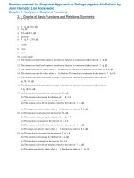
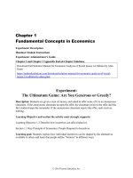
6. Draw a graph of the components for an elevator-position control. Indicate how you would measure the position of the elevator car. Consider a
combined coarse and …ne measurement system. What accuracies do you
suggest for each sensor? Your system should be able to correct for the
fact that in elevators for tall buildings there is signi…cant cable stretch as
a function of cab load.
Solution:
A coarse measurement can be obtained by an electroswitch located before
the desired ‡oor level. When touched, the controller reduces the motor
speed. A “…ne” sensor can then be used to bring the elevator precisely
to the ‡oor level. With a sensor such as the one depicted in the …gure,
a linear control loop can be created (as opposed to the on-o¤ type of the
coarse control).Accuracy required for the course switch is around 5 cm;
for the …ne ‡oor alignment, an accuracy of about 2 mm is desirable to
eliminate any noticeable step for those entering or exiting the elevator.
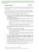
7. Feedback control requires being able to sense the variable being controlled.
Because electrical signals can be transmitted, ampli…ed, and processed
easily, often we want to have a sensor whose output is a voltage or current
proportional to the variable being measured. Describe a sensor that would
give an electrical output proportional to:
© 2015 Pearson Education, Inc., Upper Saddle River, NJ. All rights reserved. This publication is protected by Copyright and written permission should be obtained
from
the publisher
prior to any prohibited reproduction, storage in a retrieval system, or transmission in any form or by any means, electronic, mechanical, photocopying,
Fullrecording,
file
ator likewise.
/>For information regarding permission(s), write to: Rights and Permissions Department, Pearson Education, Inc., Upper Saddle River, NJ 07458.
Solution Manual for Feedback Control of Dynamic Systems 7th Edition by Franklin
Full file at />
1.1. PROBLEMS AND SOLUTIONS
1007
(a) temperature
(b) pressure
(c) liquid level
(d) ‡ow of liquid along a pipe (or blood along an artery) force
(e) linear position
(f) rotational position
(g) linear velocity
(h) rotational speed
(i) translational acceleration
(j) torque
Solution:
Sensors for feedback control systems with electrical output. Examples
(a) Temperature: Thermistor- temperature sensitive resistor with resistance change proportional to temperature; Thermocouple; Thyristor.
Modern thermostats are computer controlled and programmable.
(b) Pressure: Strain sensitive resistor mounted on a diaphragm which
bends due to changing pressure
(c) Liquid level: Float connected to potentiometer. If liquid is conductive
the impedance change of a rod immersed in the liquid may indicate
the liquid level.
(d) Flow of liquid along a pipe: A turbine actuated by the ‡ow with a
magnet to trigger an external counting circuit. Hall e¤ect produces
an electronic output in response to magnetic …eld changes. Another
© 2015 Pearson Education, Inc., Upper Saddle River, NJ. All rights reserved. This publication is protected by Copyright and written permission should be obtained
from
the publisher
prior to any prohibited reproduction, storage in a retrieval system, or transmission in any form or by any means, electronic, mechanical, photocopying,
Fullrecording,
file
ator likewise.
/>For information regarding permission(s), write to: Rights and Permissions Department, Pearson Education, Inc., Upper Saddle River, NJ 07458.
Solution Manual for Feedback Control of Dynamic Systems 7th Edition by Franklin
Full file at />
1008CHAPTER 1. AN OVERVIEW AND BRIEF HISTORY OF FEEDBACK CONTROL
way: Measure pressure di¤erence from venturi into pressure sensor
as in …gure; Flowmeter. For blood ‡ow, an ultrasound device like a
SONAR can be used.
(e) Position.
When direct mechanical interaction is possible and for “small” displacements, the same ideas may be used. For example a potentiometer may be used to measure position of a mass in an accelerator (h).
However in many cases such as the position of an aircraft, the task is
much more complicated and measurement cannot be made directly.
Calculation must be carried out based on other measurements, for
example optical or electromagnetic direction measurements to several
known references (stars,transmitting antennas ...); LVDT for linear,
RVDT for rotational.
(f) Rotational position. The most common traditional device is a potentiometer. Also common are magnetic machines in which a rotating
magnet produces a variable output based on its angle.
(g) Linear velocity. For a vehicle, a RADAR can measure linear velocity.
In other cases, a rack-and-pinion can be used to translate linear to
rotational motion and an electric motor(tachometer) used to measure
the speed.
(h) Speed: Any toothed wheel or gear on a rotating part may be used to
trigger a magnetic …eld change which can be used to trigger an electrical counting circuit by use of a Hall e¤ect (magnetic to electrical)
sensor. The pulses can then be counted over a set time interval to
produce angular velocity: Rate gyro; Tachometer
(i) Acceleration: A mass movement restrained by a spring measured by
a potentiometer. A piezoelectric material may be used instead (a material that produces electrical current with intensity proportional to
acceleration). In modern airbags, an integrated circuit chip contains
a tiny lever and ’proof mass’whose motion is measured generating a
voltage proportional to acceleration.
© 2015 Pearson Education, Inc., Upper Saddle River, NJ. All rights reserved. This publication is protected by Copyright and written permission should be obtained
from
the publisher
prior to any prohibited reproduction, storage in a retrieval system, or transmission in any form or by any means, electronic, mechanical, photocopying,
Fullrecording,
file
ator likewise.
/>For information regarding permission(s), write to: Rights and Permissions Department, Pearson Education, Inc., Upper Saddle River, NJ 07458.
Solution Manual for Feedback Control of Dynamic Systems 7th Edition by Franklin
Full file at />
1.1. PROBLEMS AND SOLUTIONS
1009
(j) Force, torque: A dynamometer based on spring or beam de‡ections,
which may be measured by a potentiometer or a strain-gauge.
8. Each of the variables listed in Problem 7 can be brought under feedback
control. Describe an actuator that could accept an electrical input and be
used to control the variables listed. Give the units of the actuator output
signal.
Solution:
(a) Resistor with voltage applied to it or mercury arc lamp to generate
heat for small devices. a furnace for a building..
(b) Pump: Pumping air in or out of a chamber to generate pressure.
Else, a ’torque motor’produces force..
(c) Valve and pump: forcing liquid in or out of the container.
(d) A valve is normally used to control ‡ow.
(e) Electric motor
(f) Electric motor
(g) Electric motor
(h) Electric motor
(i) Translational acceleration is usually controlled by a motor or engine
to provide force on the vehicle or other object.
(j) Torque motor. In this motor the torque is directly proportional to
the input (current).
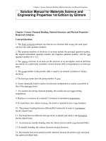
9. Feedback in Biology
(a) Negative Feedback in Biology: When a person is under long term stress
(say a couple of weeks before an exam!), hypothalamus (in the brain) secretes a hormone called CRF (Corticotrophin Releasing Factor) which
binds to a receptor in the pituitary gland stimulating it to produce ACTH
(Adrenocorticotropic hormone), which in turn stimulates the adrenal cortex (outer part of the adrenal glands) to release the stress hormone Glucocorticoids (GC). This in turn shuts down (turns o¤ the stress response)
for both CRF and ACTH production by negative feedback via the bloodstream until GC returns to its normal level. Draw a block diagram of this
closed-loop system.
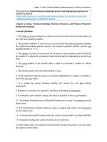
(b) Positive Feedback in Biology: This happens in some unique circumstances. Consider the birth process of a baby. Pressure from the head
of the baby going through the birth canal causes contractions via secretion of a hormone called Oxytocin which causes more pressure which in
turn intensi…es contractions. Once the baby is born, the system goes back
to normal (negative feedback). Draw a block diagram of this closed-loop
system.
Solution:
© 2015 Pearson Education, Inc., Upper Saddle River, NJ. All rights reserved. This publication is protected by Copyright and written permission should be obtained
from
the publisher
prior to any prohibited reproduction, storage in a retrieval system, or transmission in any form or by any means, electronic, mechanical, photocopying,
Fullrecording,
file
ator likewise.
/>For information regarding permission(s), write to: Rights and Permissions Department, Pearson Education, Inc., Upper Saddle River, NJ 07458.
Solution Manual for Feedback Control of Dynamic Systems 7th Edition by Franklin
Full file at />
1010CHAPTER 1. AN OVERVIEW AND BRIEF HISTORY OF FEEDBACK CONTROL
(a) Negative Feedback in Biology - Stress
Stress induced negative feedback
(b) Positive Feedback in Biology - Child birth
Child birth induced positive feedback
© 2015 Pearson Education, Inc., Upper Saddle River, NJ. All rights reserved. This publication is protected by Copyright and written permission should be obtained
from
the publisher
prior to any prohibited reproduction, storage in a retrieval system, or transmission in any form or by any means, electronic, mechanical, photocopying,
Fullrecording,
file
ator likewise.
/>For information regarding permission(s), write to: Rights and Permissions Department, Pearson Education, Inc., Upper Saddle River, NJ 07458.